Journal of Intelligent Learning Systems and Applications
Vol.5 No.4(2013), Article ID:39436,8 pages DOI:10.4236/jilsa.2013.54021
SOMS: A Subway Operation and Maintenance System Based on Planned Maintenance Model with Train State
![]()
1Guangzhou Metro, Guangzhou, China; 2School of Traffic and Transportation, Beijing Jiaotong University, Beijing, China.
Email: *10114240@bjtu.edu.cn
Copyright © 2013 Jianlong Ding et al. This is an open access article distributed under the Creative Commons Attribution License, which permits unrestricted use, distribution, and reproduction in any medium, provided the original work is properly cited.
Received May 4th, 2013; revised September 4th, 2013; accepted October 6th, 2013
Keywords: subway operation and maintenance system (SOMS); condition-based maintenance; planned maintenance
ABSTRACT
This paper aims to propose a modeling framework for subway operation and maintenance system (SOMS), which analyzes the train condition data based on both train sensor network data and basis train maintenance plan. The system is formulated into five function modules, and the research problem is to determine one auxiliary maintains plan, including the time allocation and frequency of maintenance. The case of Guangzhou metro is conducted to illustrate the applicability of SOMS, and the results reveal a number of interesting insights into subway maintenance system, i.e., the worksheet can reduce duplication of redundant maintenance work, the repair cost, and the damage caused by frequent disassembly.
1. Introduction
The main subway maintenance system used in many metro corporations is the planned maintenance project. Namely, the repair personnel and repair procedures are based on repair of routine monitoring item. Due to the complexity, necessity and the availability of database, the routine monitoring project is usually divided into daily inspection, monthly inspection, overhaul and half year repair [1]. The planned maintenance mode is the proposed mode based on the analysis of historical experience. Limited by the traditional formation, this mode rarely updated results in obsolete procedures, and it’s the reason that the planned maintenance mode backward for the subway maintenance requires. For example, the relay reliability will be changed if the metro corporation replaces a different set of relay, but the existing repair rules are not updated even there is a qualitative leap of relay [2]. So, the maintenance cycle should be increased but not, and the replacement frequency should be reduced but not. That is the problem which we focus on. This paper proposed the SOMS based on the results of train fault monitoring, hidden danger mining and the repair state.
The remainder of the paper is organized as follows. Section 2 states the structure of the research problem. Section 3 analyses the reliability of SOMS. Section 4 proposes the resource optimal allocation algorithm. Section 5 shows the maintenance plan applied in this system.
2. Structure of the SOMS
The system is composed of five main function modules: train monitoring, train safety assessment, repair the redundancy design, optimize the allocation of resources and repair planning [3]. Auxiliary modules are database backstage and data management module. The basic structure of the system is shown in figure 1.
Train running status monitoring module will receive and resolve data of maintenance, by means of selection and calculation of data, key data related to maintenance shall be gathered. At the same time it receives and stores on-board diagnosis host and train potential excavating diagnosis data provided by the server. Safety assessment module will do train safety assessment with the state monitoring data, while fault analysis of key components and life time evaluation of hidden danger information screening will be performed. According to the evaluation results, scale and costs of the repair can be estimated, with report given by this system, decision can be made for operation and maintenance. With urgency, time estimation, time supply estimation, repair personnel ar-
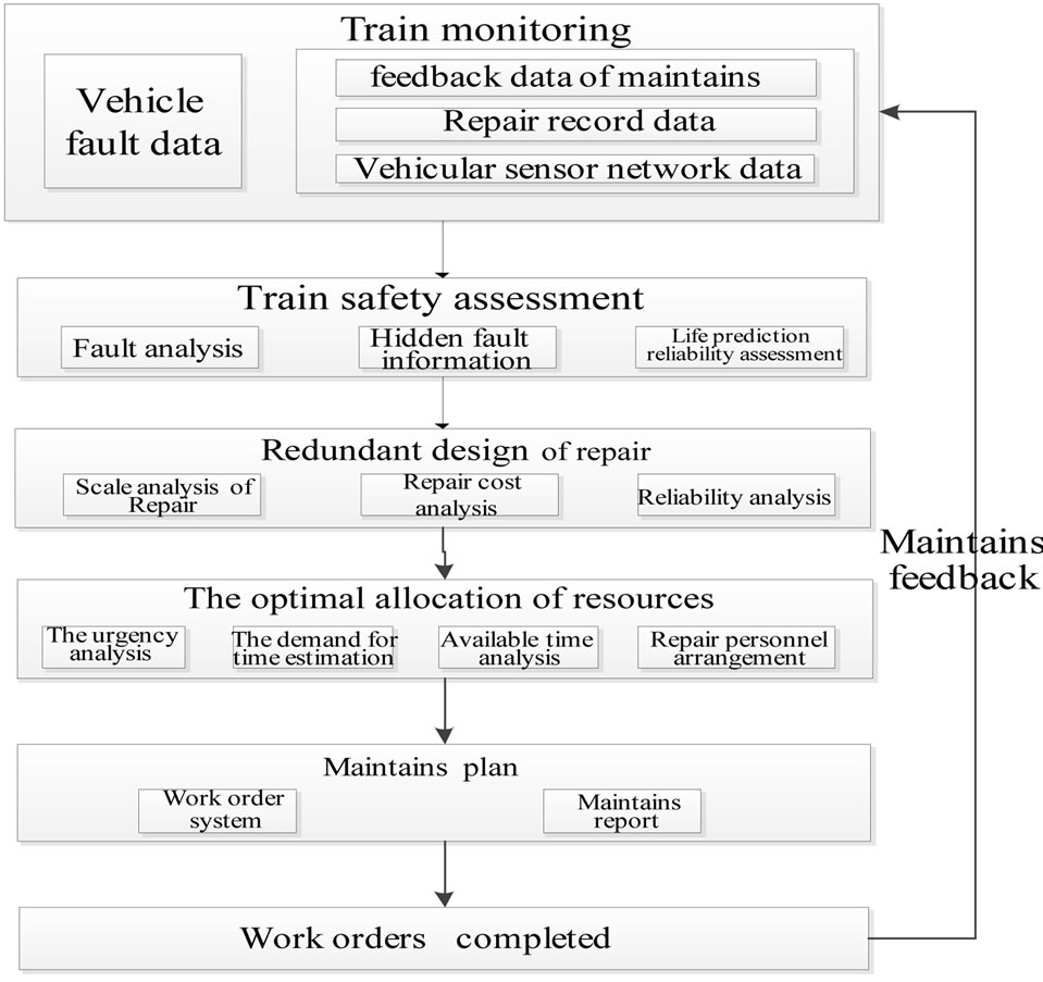
Figure 1. Structure of SOMS.
rangements recommendations, after fine-tuning of maintenance personnel, maintenance plan can be made, scheduling will be send to monitor for repair processing.
Subway operation and maintenance system interfaces is shown in figure 2.
3. Reliability Analysis of SOMS
In operation and maintenance of metro corporation, component life, employees repair level and performance are key aspects of operation and maintenance personnel [4]. As a basic requirement, this system mainly uses three types of system reliability prediction reliability algorithm: 1) The design life of components; 2) Prediction of the operation life of components; 3) Component repair operation reliability. In this system, reliability analysis works as a service, and data processing starts daily on time. After results were stored in the database, reliability data table is updated. While reliability data exceeds threshold, service will push fault information to the user interface for further operation.
3.1. Analysis of Components in the Real Life
Design life is different from the real operation life, which is closer to the actual calculation of real use condition. It can be used to calculate the component life. This method relies on the analysis method to establish the actual life of the equipment model, calibrating model parameters, and calculating of the actual life of the equipment in data driven model [5,6]. The required data from the record fault data as line number and the total number of damaged parts, trains operation mileage, and vehicle running time.
Step 1: Calculate the total count of damaged parts using N; Step 2: Consider t, and t is the daily operation of the vehicle hours; Step 3: Calculate total operating mileage D, and set the line number as a, date for the I, the line operation the number of days for the S, the car a total of P; Step 4: At last, calculate the mean time to failure
 and then the average fault-free working range is
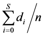 .
.
3.2. Prediction of the Operation Life of Components
Firstly, calling equipment information and maintenance plans, setting up statistical distribution equipment intact rate and operation time between prediction models of operating life of equipment. Secondly, calibrating model parameters, and forming predictive ability of operating life. The input data is part name, part number, location, and maintenance database.
Limited to the integrity of the data, currently running life prediction can only do analysis on maintenance database in the system data. Because the maintenance data mainly for the running gear in a database system, it belongs to the mechanical components and has the shape and scale parameters. It is very suitable for Weibull distribution data model. Base on data gathered, it is possible to calculate with corresponding compensation. For example, we can get wheel cutting data. After inputting wheel cutting data into the two-parameter Weibull distribution calculation model, we can draw parameters of the scale and shape, and do calculating based on these parameters.
3.3. Component Repair Operation Reliability
Combined with databases of personnel and maintenance, the statistical data of maintenance speed and quality, the distribution relationships between maintenance and completion time are formed. By data mining of the personnel mark of personnel database, we can get capability assessment of the staff. The input data is defined as a class which contains the job ID, employee ID, work time, field of maintenance database table and personnel database table.
For sub tasks, define an ID: i. We define the time of task completed as T, the number of employee as s, the repair time can be defined as the average of cumulative homework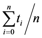 . Based on the average value of all the staff, we will get the variance and standard deviation. And then with the average operation time of single employee, we can calculate deviation of the variance and standard deviation. Comparative analysis shows the dif-
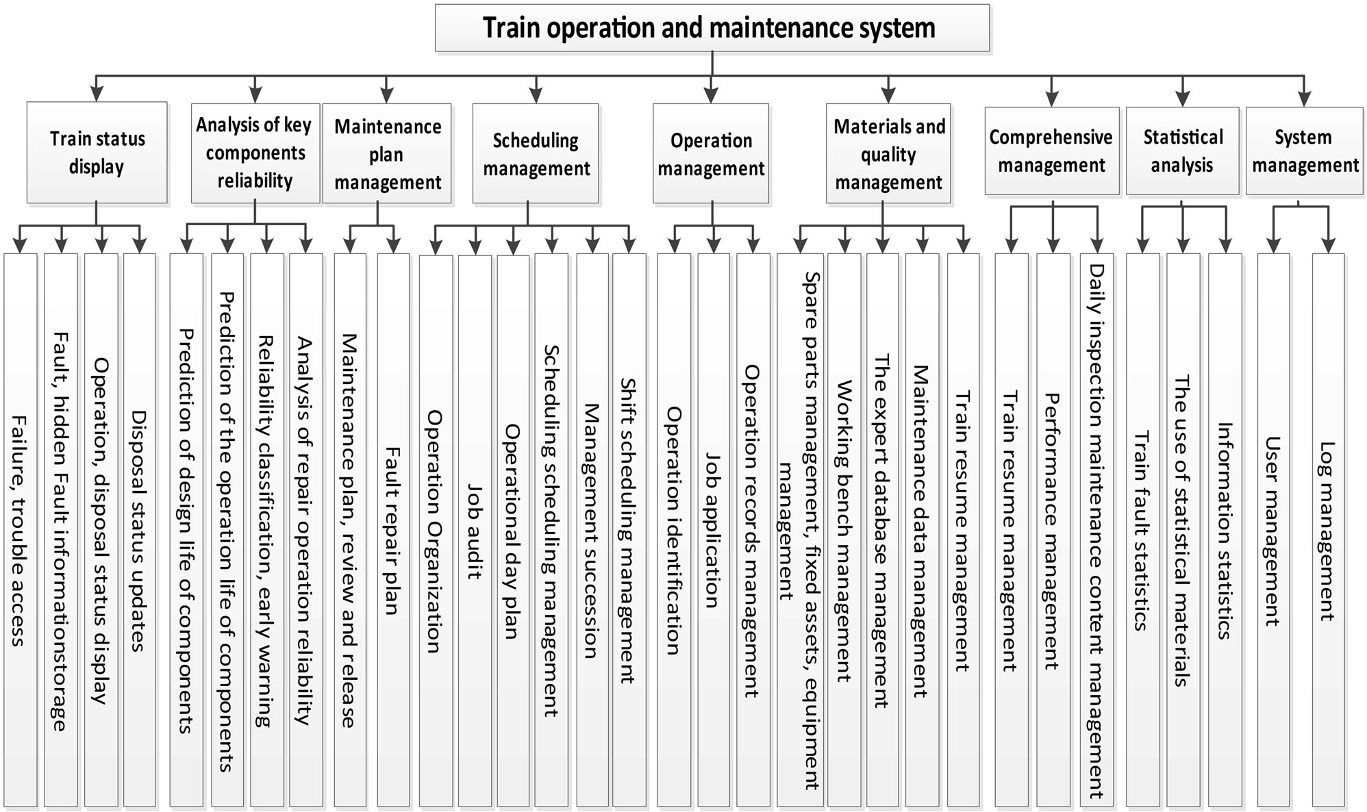
Figure 2. Interfaces of subway operation and maintenance system.
ference of staff completion efficiency variance and standard deviation as well as the reliability in the repair process.
3.4. Subway Operation and Maintenance System Data Model Design
In order to achieve the operation and maintenance of the system, operation and maintenance of the database should be established, include building the appropriate fields. This system stored data in an Oracle database. The database table is shown as follows: The maintenance experts suggest table, Maintenance schedule, Spare parts table, Equipment resume, Equipment reliability table, The maintenance resource information table, The maintenance resource status table, Maintenance reliability table, Fault code table and Related departments table. Each table established relations by numbers and code field.
According to the type of data, the data model of the system is divided into static data model and dynamic data model. Static data model means the field does not change with the increase in business. We can treat the data model using traditional relational database. Static data model is shown as follows:
The maintenance experts suggest database: Fault code, Fault location, The type of fault, Time to failure, The severity of the fault, Maintenance finished, Repair method, Replacement of spare parts required number, Replacement required tools, Repair time estimates, Replace the estimated time, The number of required components, Fault severity level, Maintenance worker category, Maintenance worker level, and Remark.
Maintenance database: Job code, Fault location, Required of replacement spare parts and tools, Estimated time, The number of required spare parts, Maintenance worker category, The number of maintenance workers, Maintenance sub-processes.
Spare parts: Part number, Type of material, Material Brand, Material prices, Amount of materials, Material specifications, Material model.
Plan of maintenance database: Maintenance project number, Maintenance job number, Job code set.
Departmental database: Department number, Department description, Staff, Sector classification.
Personnel database: Department number, Name, Birth, Level, Working time, Length of service.
Dynamic database model is changed in the process of operation. For this type of database, if we use static design, once the change happened, it will be difficult to adjust in the late stage.
The main idea of the dynamic data model design is to find out common characteristics to multiple data models and set up these characteristics with serial numbers, establish a mapping between the number and specific description, and record it in the mapping table.
In accordance with design principles of dynamic data model, datasheet is designed as follows:
Vehicle equipment history: Equipment biographical numbers, and the number of abstract attribute equipment. Device abstraction properties include number of spare parts and equipment location.
Equipment failure history table: Equipment biographical numbers, the number of abstract attribute about equipment failure. At present abstract properties include operating time, operating instructions, description of the problem, and closing kilometers.
Maintenance of resource information: Number of Maintenance resources and maintenance resources abstract attributes. Abstract properties include state, name, and number of resources.
Reliability data: Equipment history number, recording time, reliability abstract attribute number and reliability data. Abstract properties include reliability type. There are 3 sorts of reliability data in reliability analysis about specific property.
Reliability INES: Reliability type and the number of reliability abstract attribute. Abstract properties include grading, threshold, and treatment recommendations.
4. Resource Optimal Allocation Algorithm
4.1. Introduction to Rough Set
Rough set theory is not an alternative to classical set theory but it is embedded in it. Rough set theory can be viewed as a specific implementation of Frege’s idea of vagueness, i.e., imprecision in this approach is expressed by a boundary region of a set, and not by a partial membership, like in fuzzy set theory.
Rough set concept can be defined quite generally by means of topological operations, interior and closure, called approximations.
Let us describe this problem more precisely. Suppose we are given a set of objects U called the universe and an indiscernibility relation , representing our lack of knowledge about elements of U. For the sake of simplicity we assume that R is an equivalence relation. Let X be a subset of U. We want to characterize the set X with respect to R. To this end we will need the basic concepts of rough set theory given below.
• The lower approximation of a set X with respect to is the set of all objects, which can be for certain classified as X with respect to R (are certainly X with respect to R).
• The upper approximation of a set with respect to R is the set of all objects which can be possibly classified as X with respect to R (are possibly X in view of R).
• The boundary region of a set X with respect to R is the set of all objects, which can be classified neither as X nor as not-X with respect to R. Now we are ready to give the definition of rough sets.
• Set X is crisp (exact with respect to R), if the boundary region of X is empty.
• Set X is rough (inexact with respect to R), if the boundary region of X is nonempty.
Thus a set is rough (imprecise) if it has nonempty boundary region; otherwise the set is crisp (precise). This is exactly the idea of vagueness proposed by Frege.
Formal definition of “information system” [7-9]
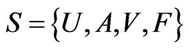
 : Finite set of objects.
 : Finite set of attributes.
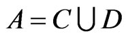 , where
  is condition attribute subsets,
  is the decision attribute subset.
 :
:  is domain of property
 .
.
 :
: is the total function, for each
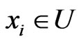 ,
,  , there exists
 .
.
A relational database can be regarded as an information system, where the “column” for the “properties”, “line” for the “object”.
4.2. Attribute Reduction Algorithm
The  is the discernibility matrix of decision table
 ,
,  ,which is all the condition attributes in the collection T. S is the set of all attributes combination in M, and S does not contain duplicates. Make sure that there are s combinations of attributes in S, each property combinations are represented as Bi. Its formulation is described as:
 ,
,  ,
,
 .
.
Make Card , each condition attribute in Bi is expressed as
 ,
,
 .
.
as  is nuclear attributes of
 ,
, .
.
• Step 1. Add the core attributes into the collection of attributes after attribute reduction, red =![]() ;
;
• Step 2. Find all attribute combination which does not contain in the discernibility matrix , as
, as
 ;
;
• Step 3. Transfer the attribute combination S and red into conjunctive normal form.
 ;
;
• Step 4.  can be converted to form of disjunctive normal form;
• Step 5. Select a satisfactory properties combination. If you want to attribute minimum number, and then directly choose the combination of the minimum number in conjunction type attribute. If you want to rule the minimalist or data reduction amount is the largest. The attribute value reduction should be carried out first.
4.3. Resource Optimization Configuration Based on Rough Set Theory
Equipment maintenance support system is a complex system, involves a variety of factors. Especially the maintenance support dynamic configuration of resources. The change of any kind of resources can cause the change of state of the whole system. And each of the resource is influenced by the factors of environment, the inherent attribute of injury and use strength. This article do researches for some abstract maintenance resources, extract four important attribute from numerous factors, The four types of condition attributes are listed below:
1) Price : 0 high, l medium, 2 low;
2) Vulnerability : 0 vulnerability, 1 medium, 2 damage resistance;
3) Importance : 0 important, 1 medium, 2 not important;
4) The damage level : 0 badly damaged 1, medium, 2 light damaged;
The resource allocation method based on Rough set is a kind of qualitative analysis method. So in this case, the decision attribute is set to 4 levels:
Configuration as d: 0 mass, 1 medium, 2 little, 3 not configured.
1) Establish maintenance resource allocation decision table. Discretization of discrete data processing is shown in table 1.
2) Calculate the discernibility matrix (see Table 2).
3) Get decision rules.
Calculated by the above, you can get two attribute reduction  and
and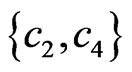 . Clearly, the core is
 . Thus we can derive the decision rules:
Rule 1: 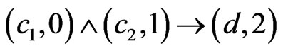
Rule 2: 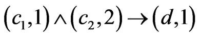
Rule 3: 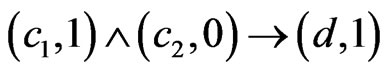
Rule 4: 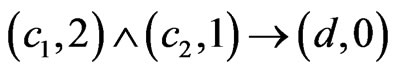
Rule 5: 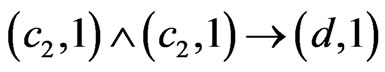
Rule 6: 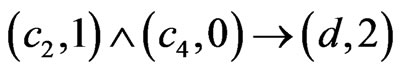
Rule 7: 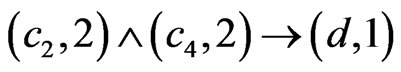
Rule 8: 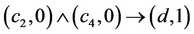
Rule 9: 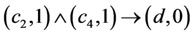
Rule 10: 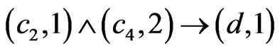
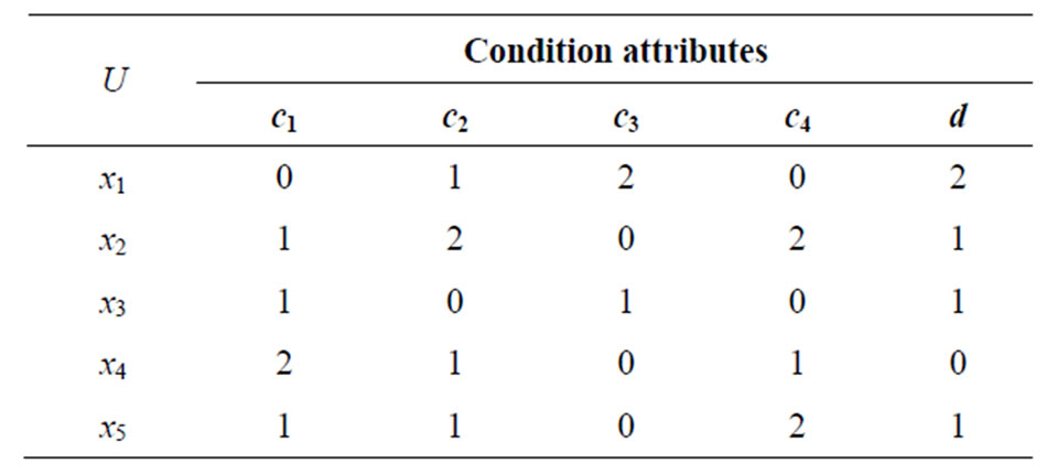
Table 1. Maintenance support resource allocation decision table.
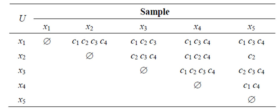
Table 2. Distinguish matrix table of maintenance support resources.
5. The Maintenance Plan
Based on data acquired, and maintenance personnel shall be able to make maintenance plan [10,11]. The maintenance plan mainly includes three aspects: 1) maintenance for special parts, 2) train fault repair, 3) hidden danger maintenance. Maintenance system framework is shown in figure 3. Expert database, spare parts database, repair workbench and personnel management library are shared for both train fault maintenance and hidden danger maintenance. Treatment recommendations are fault maintenance mode recommendation, maintenance time recommendation, personnel recommendation and spare parts recommendation.
Three types of maintenance plans are taken into use for the whole system: the systematically maintenance plan, the train temporary fault maintenance plan and the train hidden danger maintenance plan.
5.1. Systematically Maintenance
Guangzhou metro is executing planned maintenance that means every train is supposed to be maintained on time every day, every month and every year. During the monthly maintenance period, the train under repair should be out of service for about one day. During the half year maintain period and one year period, the time is expanded to about 3 and 5 days. This type of maintain mode is too rigid to work, it does not take the actual running state into consideration, it not only increase the reserve of spare train, the maintenance cost but also cause the lack of maintenance or redundancy.
In order to cut the costs for maintenance, improve the trouble-free time of the train, systematically maintenance is proposed as shown in Figure 4. Systematically maintenance is a sort of technique that make every single maintenance procedure dispersed to 12 months, so we can make the use of time that train stay in repair base during free time.
The formation of systematically maintenance is divided into three steps: editing and auditing of monthly maintenance plan, editing and auditing of weekly maintenance plan, daily maintenance planning.
Editing and auditing of monthly maintenance plan are completed by production administrators and department
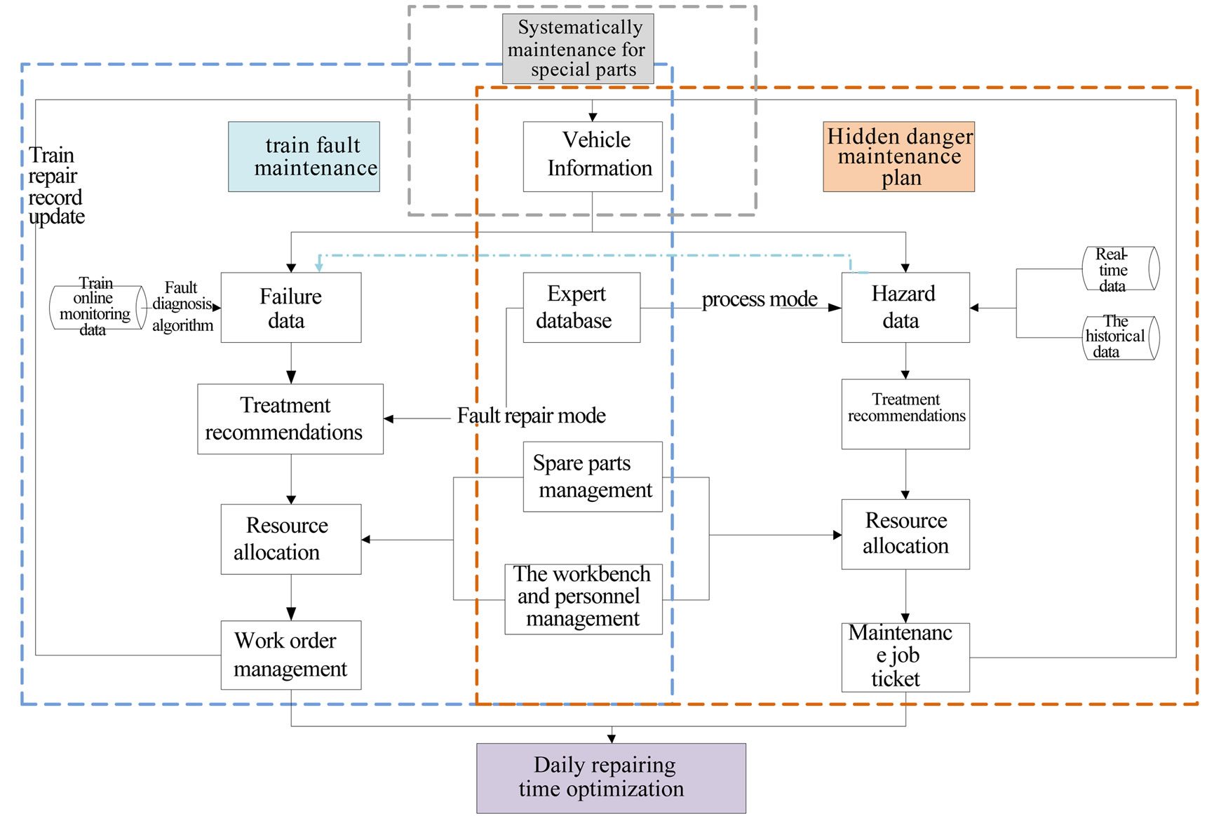
Figure 3. The whole maintenance business flow chart.
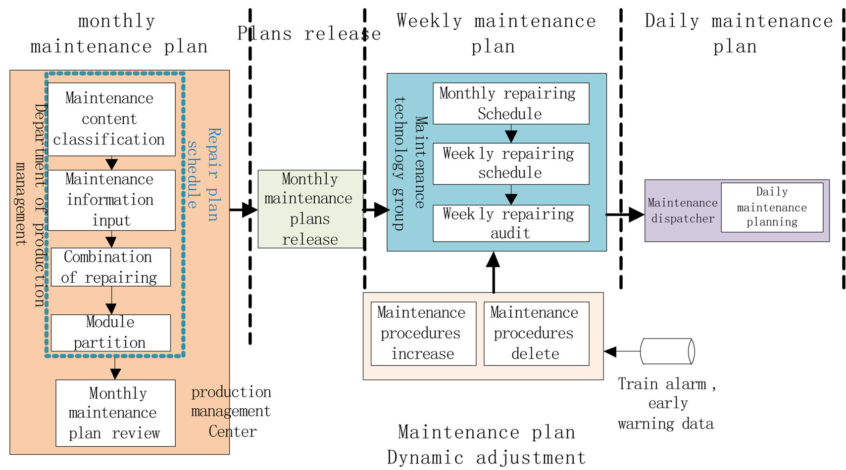
Figure 4. System maintenance processing.
administrators. The compilation and review of monthly maintenance plan are completed by the production department manager, department manager and production manager of production center. Editing and auditing of weekly maintenance plan is made by technicians, technical team leader and division director. Daily maintenance plan is done by the division of the dispatcher.
First the administrator of production department make special parts repair plan for 12 months, then submit it to the department manager and the center of production manager for approval. Secondly the maintenance technician make special parts maintenance plan for weekly maintenance plan according to monthly special parts maintenance plan and submit it to the technical team leader and division director for approval. After that users can dynamically adjust the maintenance plan according to the train operation history data. Finally maintenance dispatcher can make daily maintenance plan according to the weekly maintenance plan.
5.2. Train Temporary Fault Maintenance Plan
With train fault data, fault analysis will be performed. At the same time, analysis, life assessment, reliability prediction is performed by server daily with repair feedback. After data recorded, the train fault is matched with the expert database, with the expert database or technician temporary maintenance recommendations provided to the temporary maintenance, temporary maintenance plan can be generated. Specific process is shown in figure 5.
Firstly, we can obtain train failure data from the train fault diagnosis system and trackside fault monitoring system. Data mining system digs out the hidden fault data, include fault name and fault level. Then we give troubleshooting advice. In order to distinguish the fault severity, the severity of fault are divided into four levels: outage requests rescue, back to station, continue running for further information, and continue to run until overhaul. For each level of fault, we should give handle recommendations prompt. Train fault codes and fault level will match failure of maintenance recommendations in the expert database. If matched, maintenance recommendations for faults should be generated after the relevant personnel’s confirming. However, if failure information cannot be matched in the expert database, technical personnel need to develop maintenance recommendations for this information. After maintenance suggestions’ generating, we need to do resource allocation of staffs, fittings, tools and the order of maintenance. Re-
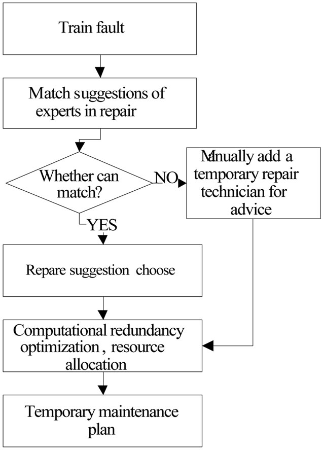
Figure 5. Temporary fault maintenance processing.
source allocation results directly in generating temporary orders on work order templates, and a formal work orders are finished after secondary editing by the relevant personnel. After work orders’ generating, online payment and reminding will be sent to the relevant departments for print. After finishing repair work, delivery record of vehicle and maintenance operations shall be transferred to complete the maintenance. The general content will be generated including maintenance personnel list, name and number of spare parts in maintenance work processing, job start/end time and repair tool. After the maintenance, the reliability evaluating data will be updated so that it can be put into use again.
5.3. Train Hidden Danger Maintenance Plan
Hidden danger data is matched to reliability scale now and then, once exceed threshold, safety evaluation work is performed. Advice of emergency response will be given. According to the potential danger severity and historical data, advice of replacement can be shown. This system can be used to compare time planning automatically for the spare parts which are frequently used. The same species of replaceable unit life comparison is taken into account in the repair or maintenance. The collective replacement shall be taken to ensure frequency of this components failure will be reduced. Entering into optimize unit, the allocation of resources, arrangement of the repair will be set according to the rank of priority, including fault classification of risk information, repair difficulty, repair time, repair workers demand. Eventually after generating of work order, repair plans are given. When repairs are completed, operators need to complete the repairs with feedback, after repair record updated and spare parts library information updated, the failure is eliminated. The train hidden danger maintenance algorithm is shown in figure 6.
First of all, locate train risk components (data from two places: 1) the data mining system, 2) the components recommended by safety assessment system). Prioritize the hidden trouble data according to the type of train and severity of fault, we will get train daily inspection plan for train components. Repair will be taken for serious hidden trouble right after daily operations, components with no serious threat will be recorded and be taken into the treasury of daily inspection after the end of the train operation, monitoring system shall pay attention to the parts in the Significant Attention Parts Table, when the tested hidden danger is upgraded to a failure, hidden dangers will be treated as fault, hidden trouble maintenance advice shall be got from the expert database, and after maintenance resource optimization configuration, maintenance documents is formed. The documents are distributed to the related maintenance team for temporary repair operations. When the hidden danger information
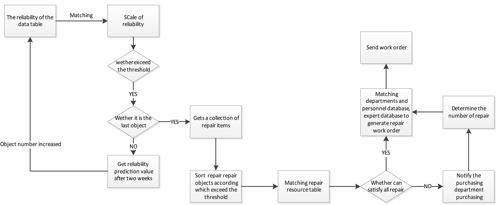
Figure 6. Train hidden danger maintenance algorithm.
raises but it does not need to repair immediately, trains can still be put into use. After the completion of the daily inspection, this train can be sent out. Attentions will be paid to train status which can prevent hidden danger upgraded to a real fault. Hidden fault data and maintenance records are stored, so that we can evaluate reliability of train maintenance in the future.
6. Conclusion
Taking Guangzhou subway operation and maintenance system as a prototype, this paper presented a system structure of SOMS then the solution for key issues, and put forward a feasible solution. The repair model established with special parts, train state and hidden danger is a good supplement for current maintenance plan. For ensuring safety, train components with uncertain reliability models will still apply the traditional planned maintenance model or systematically maintenance model. For components whose status data are sufficient, hidden danger maintenance model will be applied. Both lab tests and field applications show that this system increases the stability of maintenance and reduces the costs.
7. Acknowledgements
This research is supported by The National High Technology Research and Development Program of China (Grant No. 2011AA110506).
REFERENCES
- H. Xu and Y. M. Mo, “Status Architecture and Realization of the Locomotive State-Overhaul Management System,” Information & Management Engineering, Vol. 27, No. 1, 2005, pp. 69-71.
- Q. W. Zhang, “Conception of Long-Span Bridge Health Monitoring and Monitoring System Design,” Journal of Tongji University, Vol. 1, No. 29, 2011, pp. 65-69.
- G. Y. Xun, T. Y. Shi and S. W. Ren, “Development of the On-Board Track Inspection System Based on Computer Vision,” China Railway Science Press, Vol. 1, No. 34, 2013, pp. 139-143.
- B. Peng, X. Jing and Y. Yang, “Research on Optimization Maintenance Method of Latent Fault Based on Residual Life,” Journal of Ordnance, Vol. 4, No. 33, 2012, pp. 483-487.
- L. Liu and W. J. Wang, “Causes of Rail Tread Oblique Crack and Countermeasures,” Materials for Mechanical Engineering, Vol. 1, No. 36, 2012, pp. 26-30.
- L. Liu and W. J. Wang, “Causes of Rail Tread Oblique Crack and Countermeasures,” Materials for Mechanical Engineering, Vol. 1, No. 36, 2012, pp. 26-30.
- G. M. Song, J. P. Cao, J. S. Song and Z. D. He, “Resources Configuration of Equipment Maintenance Support Based on Rough Set Theory,” Computer Engineering, Vol. 33, No. 4, 2007, pp. 220-222.
- W. Q. Li, J. Wang and Y. Ma, “Optimal Allocation of Emergency Resource for Urban Rail Transit Network,” Modern Urban Transit, No. 4, 2009, pp. 9-13.
- S. Shan, L.-M. Liu, J.-X. Chen, Q. Du and M. Wang, “Real Time Monitor and Intelligent Diagnosis and Maintain Support System for Locomotive Status,” Electric Drive for Locomotives, No. 5, 2009, pp. 40-43.
- D. B. Shao, “Application of Condition-Based Metro Equipment Maintenance Based on Vibration Monitoring,” Urban Mass Transit, Vol. 15, No. 7, 2012, pp. 79-119.
- Z. L. Wu, J. G. Yang, J. L. Zhang and S. M. Zhao, “Application of Intelligent Fault Diagnosis in Maintenance of Station Equipment for Urban Rail Transit,” Urban Rapid Rail Transit, Vol. 21, No. 5, 2008, pp. 79-81.
NOTES
*Corresponding author.