Paper Menu >>
Journal Menu >>
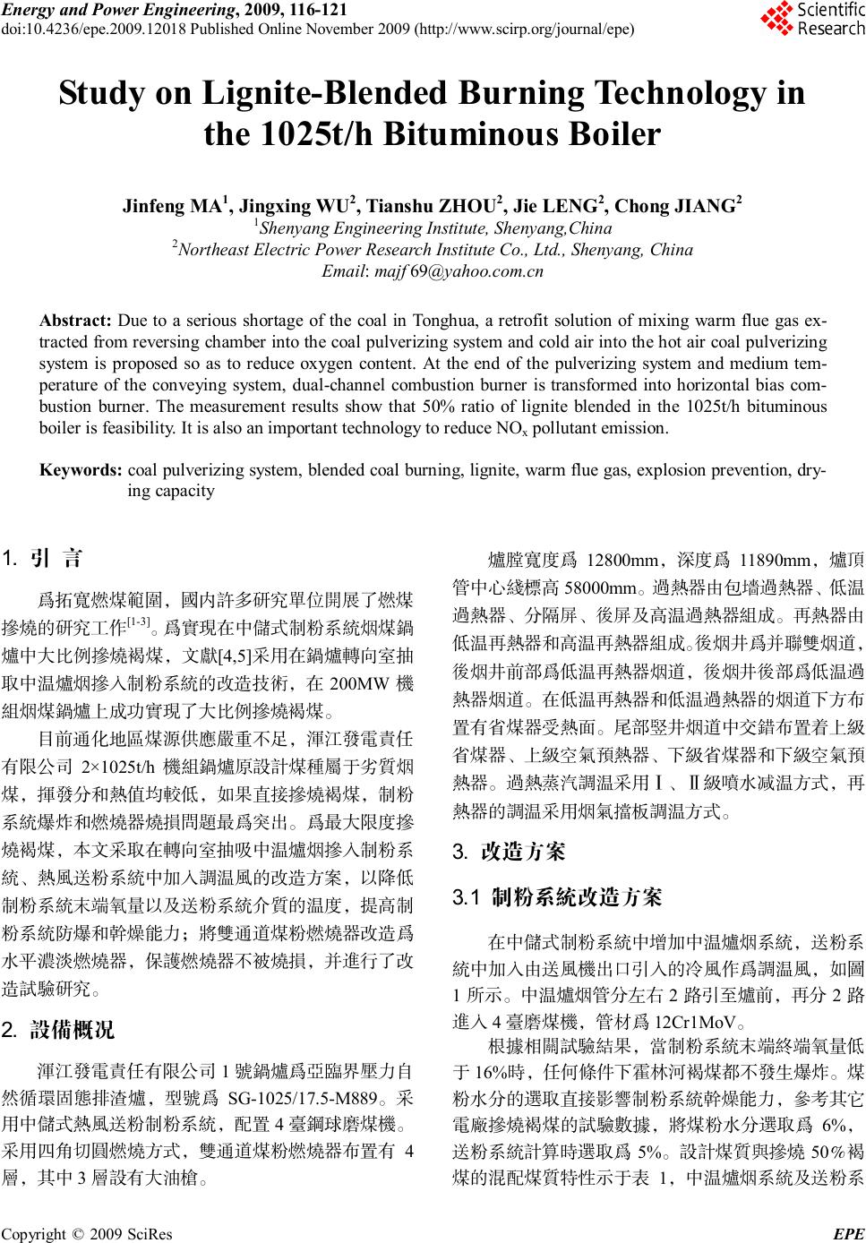 Energy and Power Engineering, 2009, 116-121 doi:10.4236/epe.2009.12018 Published Online November 2009 (http://www.scirp.org/journal/epe) Copyright © 2009 SciRes EPE Study on Lignite-Blended Burning Technology in the 1025t/h Bituminous Boiler Jinfeng MA1, Jingxing WU2, Tianshu ZHOU2, Jie LENG2, Chong JIANG2 1Shenyang Engineering Institute, Shenyang,China 2Northeast Electric Power Research Institute Co., Ltd., Shenyang, China Email: majf 69@yahoo.com.cn Abstract: Due to a serious shortage of the coal in Tonghua, a retrofit solution of mixing warm flue gas ex- tracted from reversing chamber into the coal pulverizing system and cold air into the hot air coal pulverizing system is proposed so as to reduce oxygen content. At the end of the pulverizing system and medium tem- perature of the conveying system, dual-channel combustion burner is transformed into horizontal bias com- bustion burner. The measurement results show that 50% ratio of lignite blended in the 1025t/h bituminous boiler is feasibility. It is also an important technology to reduce NOx pollutant emission. Keywords: coal pulverizing system, blended coal burning, lignite, warm flue gas, explosion prevention, dry- ing capacity 1. 引 言 为拓宽燃煤范围,国内许多研究单位开展了燃煤 掺烧的研究工作[1-3]。为实现在中储式制粉系统烟煤锅 炉中大比例掺烧褐煤,文献[4,5]采用在锅炉转向室抽 取中温炉烟掺入制粉系统的改造技术,在 200MW 机 组烟煤锅炉上成功实现了大比例掺烧褐煤。 目前通化地区煤源供应严重不足,浑江发电责任 有限公司 2×1025t/h 机组锅炉原设计煤种属于劣质烟 煤,挥发分和热值均较低,如果直接掺烧褐煤,制粉 系统爆炸和燃烧器烧损问题最为突出。为最大限度掺 烧褐煤,本文采取在转向室抽吸中温炉烟掺入制粉系 统、热风送粉系统中加入调温风的改造方案,以降低 制粉系统末端氧量以及送粉系统介质的温度,提高制 粉系统防爆和干燥能力;将双通道煤粉燃烧器改造为 水平浓淡燃烧器,保护燃烧器不被烧损,并进行了改 造试验研究。 2. 设备概况 浑江发电责任有限公司 1号锅炉为亚临界压力自 然循环固态排渣炉,型号为SG-1025/17.5-M889。采 用中储式热风送粉制粉系统,配置 4台钢球磨煤机。 采用四角切圆燃烧方式,双通道煤粉燃烧器布置有4 层,其中3层设有大油枪。 炉膛宽度为12800mm ,深度为11890mm,炉顶 管中心线标高 58000mm。过热器由包墙过热器、低 温 过热器、分隔屏、后屏及高温过热器组成。再热器由 低温再热器和高温再热器组成。后烟井为并联双烟道, 后烟井前部为低温再热器烟道,后烟井后部为低温过 热器烟道。在低温再热器和低温过热器的烟道下方布 置有省煤器受热面。尾部竖井烟道中交错布置着上级 省煤器、上级空气预热器、下级省煤器和下级空气预 热器。过热蒸汽调温采用Ⅰ、Ⅱ级喷水减温方式,再 热器的调温采用烟气挡板调温方式。 3. 改造方案 3.1 制粉系统改造方案 在中储式制粉系统中增加中温炉烟系统,送粉系 统中加入由送风机出口引入的冷风作为调温风,如图 1所示。中温炉烟管分左右 2路引至炉前,再分2路 进入4台磨煤机,管材为12Cr1MoV。 根据相关试验结果,当制粉系统末端终端氧量低 于16%时,任何条件下霍林河褐煤都不发生爆炸。煤 粉水分的选取直接影响制粉系统干燥能力,参考其它 电厂掺烧褐煤的试验数据,将煤粉水分选取为 6%, 送粉系统计算时选取为5%。设计煤质与掺烧 50%褐 煤的混配煤质特性示于表1,中温炉烟系统及送粉系 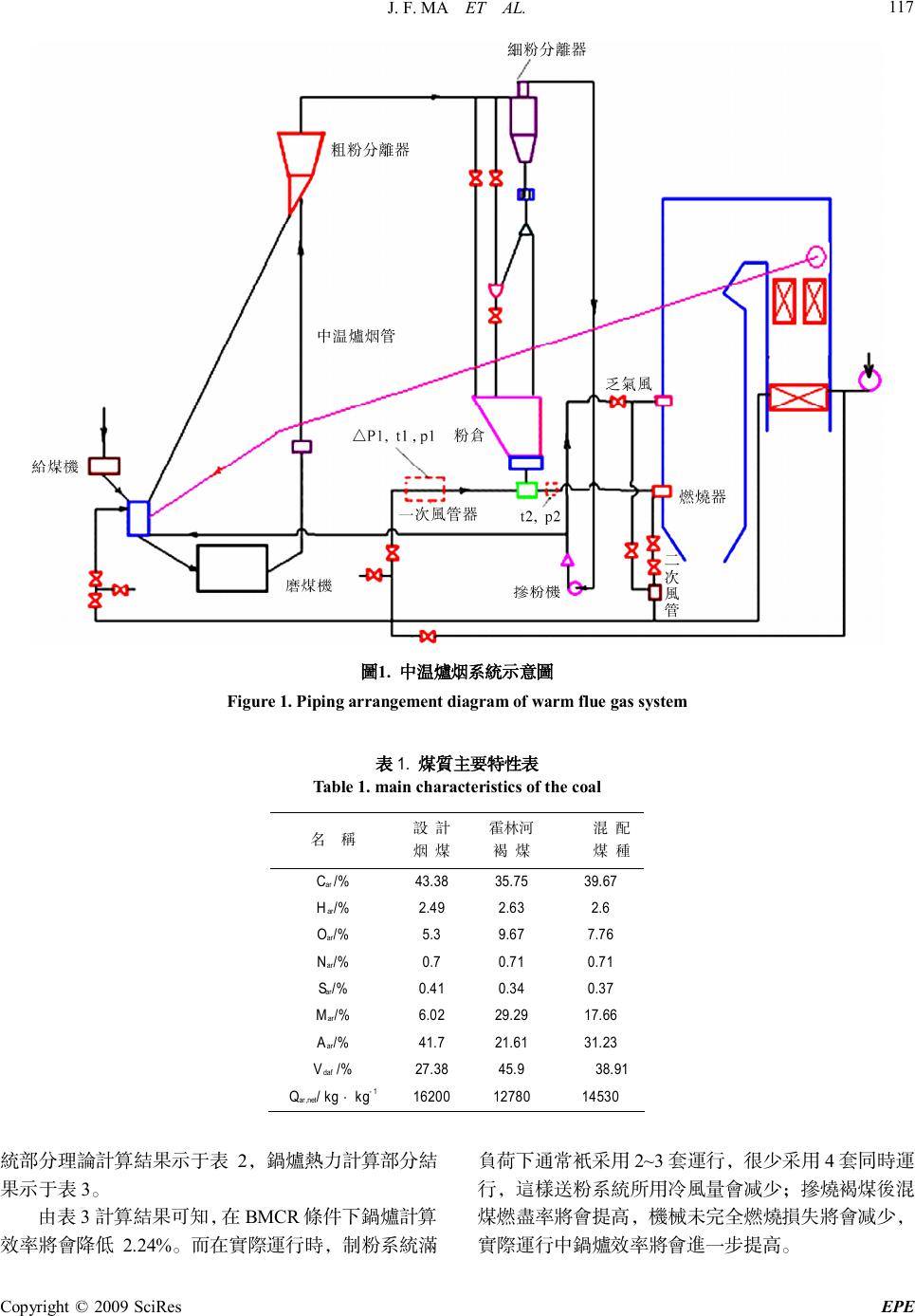 J. F. MA ET AL. Copyright © 2009 SciRes EPE 117 图1. 中温炉烟系统示意图 Figure 1. Piping arrangement diagram of warm flue gas system 表1. 煤质主要特性表 Table 1. main characteristics of the coal 名 称 设 计 烟 煤 霍林河 褐 煤 混 配 煤 种 Car /% 43.38 35.75 39.67 Har/% 2.49 2.63 2.6 Oar/% 5.3 9.67 7.76 Nar/% 0.7 0.71 0.71 Sar/% 0.41 0.34 0.37 Mar/% 6.02 29.29 17.66 Aar/% 41.7 21.61 31.23 Vdaf /% 27.38 45.9 38.91 Qar,net/ kg ⋅ kg-1 16200 12780 14530 统部分 理论计算结果示于表2,锅炉热力计算部分结 果示于表3。 由表 3计算结果可知,在 BMCR 条件下锅炉计算 效率将会降低 2.24%。而在实际运行时,制粉系统满 负荷下通常只采用2~3 套运行,很少采用 4套同时运 行,这样送粉系统所用冷风量会减少;掺烧褐煤后混 煤燃尽率将会提高,机械未完全燃烧损失将会减少, 实际运行中锅炉效率将会进一步提高。 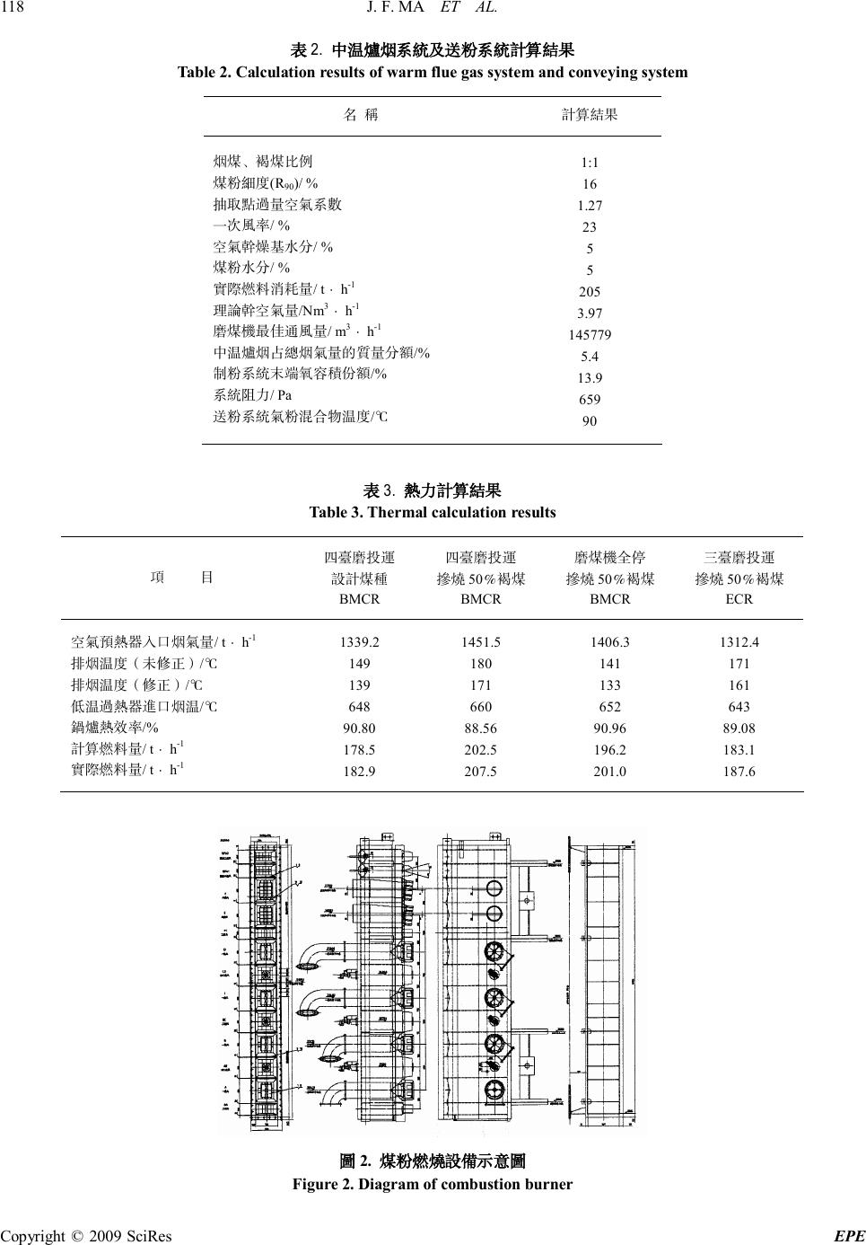 J. F. MA ET AL. Copyright © 2009 SciRes EPE 118 表2. 中温炉烟系统及送粉系统计算结果 Table 2. Calculation results of warm flue gas system and conveying system 名 称 计算结果 烟煤、褐煤比例 煤粉细度(R90)/ % 抽取点过量空气系数 一次风率/ % 空气干燥基水分/ % 煤粉水分/ % 实际燃料消耗量/ t ⋅ h-1 理论干空气量/Nm3 ⋅ h-1 磨煤机最佳通风量/ m3 ⋅ h-1 中温炉烟占总烟气量的质量分额/% 制粉系统末端氧容积份额/% 系统阻力/ Pa 送粉系统气粉混合物温度/℃ 1:1 16 1.27 23 5 5 205 3.97 145779 5.4 13.9 659 90 表3. 热力计算结果 Table 3. Thermal calculation results 项 目 四台磨投运 设计煤种 BMCR 四台磨投运 掺烧 50%褐煤 BMCR 磨煤机全停 掺烧 50%褐煤 BMCR 三台磨投运 掺烧 50%褐煤 ECR 空气预热器入口烟气量/ t ⋅ h-1 排烟温度(未修正)/℃ 排烟温度(修正)/℃ 低温过热器进口烟温/℃ 锅炉热效率/% 计算燃料量/ t ⋅ h-1 实际燃料量/ t ⋅ h-1 1339.2 149 139 648 90.80 178.5 182.9 1451.5 180 171 660 88.56 202.5 207.5 1406.3 141 133 652 90.96 196.2 201.0 1312.4 171 161 643 89.08 183.1 187.6 图2. 煤粉燃烧设备示意图 Figure 2. Diagram of combustion burner  J. F. MA ET AL. Copyright © 2009 SciRes EPE 119 3.2. 燃烧器改造方案 燃烧器原设计采用大速差双通道煤粉燃烧器,一 次风喷口布置相对集中。掺烧褐煤的混配煤质着火性 能和燃尽性能提高,同时结焦倾向也增加,因此将燃 烧器改为均等配风布置。燃烧器四角的安装角度不变, 燃烧器水冷套不变,燃烧器各层风室重新分配(调整 风室高度),调整全部一、三次风标高,调整二层刚性 梁标高等。同时改变设计参数,如提高一次风率和风 速等。燃烧设备示意图如图2所示。 该燃烧器设计特点如下: (1) 采用中温炉烟+热风+冷风+再循环送粉系统。 (2) 一次风设计采用成熟的WR水平浓淡燃烧器。 一次风喷嘴中装有V型钝体,在 V型 钝体前方形成稳 定的回流区卷吸高温烟气,起到稳燃作用。燃烧器的 一次风喷嘴采用均等布置,三次风喷嘴集中布置。 (3) 二次风设计按“加强混合,分级燃烧”的原 则进行,既有利于着火、稳燃和燃烬,又减少NOx的 生成量。在燃烧器顶部设置2层燃烬风,为手动摆动 喷嘴,其余喷嘴均为固定喷嘴。射流旋转方向与其余 的一、二次风射流旋转方向相反,以减少锅炉水平烟 道左右两侧的烟温偏差。 4. 中温炉烟系统投运试验 4.1. 抽热炉烟试验结果 为验证本次改造的实际效果,现场设备安装完成 后,进行了磨煤机额定出力下抽吸中温炉烟试验。试 验过程中炉烟调节挡板保持全开,通过改变磨煤机入 口负压调整中温炉烟量以及制粉系统末端氧量。磨煤 机入口负压与制粉系统末端含氧量、抽取烟气量的关 系曲线如图3、图4所示。 1100 1200 1300 1400 1500 1600 14.0 14.5 15.0 15.5 16.0 16.5 17.0 制 粉系 统 末 端 氧 量 /% 磨 煤 机 入 口 负 压 /Pa D 制 粉系 统 末 端 氧 量 C 制 粉系 统 末 端 氧 量 图3. 磨煤机入口压力与制粉系统末端含氧量关系图 Figure 3. Interrelation between oxygen content at the end 1100 1200 1300 1400 1500 1600 50000 55000 60000 65000 70000 75000 80000 85000 抽 吸 烟 气 量 /m 3 .h -1 磨 煤 机 入 口 负 压 /Pa D 磨 煤 机 抽 吸 烟 气 量 C 磨 煤 机 抽 吸 烟 气 量 图4. 磨煤机入口压力与抽取烟气量关系图 Figure 4. Interrelation between flue gas flow rate 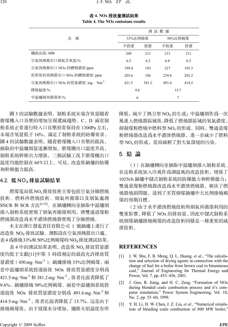 J. F. MA ET AL. Copyright © 2009 SciRes EPE 120 表4. NOx 排放量测试结果 Table 4. The NOx emissions results 测 试 数 据 33%比例褐煤 50%比例褐煤 名 称 不投运 投运 不投运 投运 机组负荷/ MW 209 211 213 211 空气预热器出口烟气含氧量/% 6.5 6.2 6.8 6.5 空气预热器出口NOx 的体积浓度/ppm 199.4 183 227 195.3 折算后的预热器出口NOx的体积浓度/ ppm 205.6 186 239.8 202.2 空气预热器出口NOx 的质 量浓度/ mg ⋅ Nm-3 421.5 381.2 491.6 414.5 降低幅度/% 9.6 15.7 中温炉烟再循环率/% 6 7 图3的试验数据表明,制粉系统末端含氧量随着 磨煤机入口负压的增加呈现递减趋势。C、D两套制 粉系统正常运行时入口负压经常保持在1300Pa 左右, 末端含氧量低于16%,满足了制粉系统的防爆要求。 图4的试验数据表明,随着磨煤机入口负压的提高, 抽取的中温炉烟量逐渐增加,磨煤机出口温度升高, 制粉系统干燥出力增强,三个试验工况下磨煤机出口 温度均能控制在 60℃以上。可见,改造后锅炉的防爆 和干燥能力提高。 4.2. 低NOX排放试验结果 燃煤电站低NOx排放技术主要包括空气分级燃烧 技术、燃料再燃烧技术、烟气再循环以及烟气处理 SNCR 和SCR 方法[6-10]。在锅炉转向室抽取中温炉烟 掺入制粉系统实现了烟气再循环利用,将双通道煤粉 燃烧器改造为水平浓淡燃烧器实现了分级燃烧。 本文在浑江发电责任有限公司 1号锅炉上进行了 改造后NOX排放试验,测点设在空气预热器出口处。 表4为掺烧33%和50%比例褐煤时NOX排放测试结果。 表4中的测试结果表明,改造后NOx排放质 量浓 度均低于文献[11]中第3时段规定的最高允许排放质 量浓度(450 -3 Nmmg⋅)。锅炉掺烧 33%比例褐煤、两 套中温炉烟系统投运前后NOx 排放质量浓度分别为 421.5 -3 Nmmg⋅和381.2 -3 Nmmg⋅,后者比前者降低了 9.6%。锅炉掺烧 50%比例褐煤、两套中温炉烟系统投 运前后NOx 排放质量浓度分别为491.6 -3 Nmmg⋅和 414.5 -3 Nmmg⋅,后者比前者降低了15.7%。这是由于 掺烧褐煤后,由于混煤水分增加,炉膛火焰温度有所 降低,减少了热力型NOX的生成;中温炉烟作为一次 风进入燃烧器区域后,降低了燃烧器区域的氧气浓度, 抑制煤粉燃烧中燃料型NOx的形成。同时,双通道煤 粉燃烧器改造为水平浓淡燃烧器,进一步减少了燃料 型NOx的形成,从而减轻了对大气环境的污染。 5. 结 论 (1)在锅炉转向室抽取中温炉烟掺入制粉系统、 在送粉系统加入冷风作为调温风的改造技术,增强了 1025t/h 锅炉中储式制粉系统的防爆能力和干燥能力; 双通道煤粉燃烧器改造为水平浓淡燃烧器,解决了燃 烧器烧损问题,达到了劣质烟煤锅炉中大比例掺烧褐 煤的预期目标。 (2)由于水平浓淡燃烧技术与烟气再循环利用的 双重影响,降低了NOx 的排放量,因此中储式制粉系 统烟煤锅炉掺烧褐煤的改造技术同样是一种重要的减 排技术。 REFERENCES [1] J. W. Shu, F. B. Meng, Q. L. Huang, et al., “The calcula- tion and selection of drying agents in connection with the change of fuel for a boiler from brown coal to bituminous coal,” Journal of Engineering for Thermal Energy and Power, Vol. 7, pp. 453–456, 2001. [2] J. Guo, R. Jiang, and H. C. Zeng, “Formation of NOx during blended coals combustion process and it’s com- puter simulation,” Power System Engineering, Vol. 10, No. 2, pp. 55–60, 1999. [3] Y. H. Li, H. W. Chen, J. Z. Liu, et al., “Numerical simula- tion of blending coals combustion of 800 MW boiler, ”  J. F. MA ET AL. Copyright © 2009 SciRes EPE 121 Proceedings of the CSEE, Vol. 22, No. 6, pp. 101–104, 2002. [4] J. X. Wu, H. G. Chen, J. F. Ma, et al., “Feasibility study on the hot flue gas mixture in coal pulverizing system of 200MW boiler,” Electric Power, Vol. 39, No. 3, pp. 22–25, 2006. [5] J. F. Ma, J. X. Wu, T. S. Zhou, et al., “Study on lignite blended burning technology in the bin and feeder coal pulverizing system,” Journal of Power Engineering, Vol. 28, No. 1, pp. 14–18, 2008. [6] S. Miyamae, T. Kiga, H. Ikebe, K. Makino, et al., “Low NOx pulverized coal combustion technology for large utility thermal power plant, ” Coal Combustion Science and Technology of Industrial and Utility Application, Hemisphere Publishing Corporation, New York, 1988. [7] M. Berg and H. Bering, “Development of a low-NOx burner for pulverized- coal combustion and retrofitting of a full-scale power plant boiler, ” Proceedings of the 2 nd International Symposia on Coal Combustion, China Ma- chine Press, Beijing, 1991. [8] E. Troconi, L. Lietti, P. Forzatti, et al., “Experimental and theoretical investigation of the dynamics of the SCR- DeNOx reaction, Chemistry Science, Vol. 51, No. 11, pp. 2965–2970, 1996. [9] C. G. Yin, S. Cailat, and J. Harion, “Investigation of flow, combustion, heat-transfer and emission from a 609MW utility tangentially fired pulverized-coal boiler,” Fuel, Vol. 81, No. 8, pp. 997–1006, 2002. [10] M. Falcite, S. Pasini, and L. Tognotti, “Modeling paractical combustion systems and predicting NOx emission with an integrated CFD based approach,” Computers and Chemi- cal Engineering, Vol. 26, No. 9, pp. 1171–1183, 2002. [11] Fossil-fuel Power Plant New Atmospheric Pollutant Emission Standard, GB13223-2003, Electric Power Press, Beijing, China, 2003. |