Materials Sciences and Applications
Vol.4 No.2(2013), Article ID:28526,8 pages DOI:10.4236/msa.2013.42019
Electro-Oxidation of Glucose in Alkaline Media on Graphene Sheets Decorated with Gold Nanoparticles
![]()
1Department of Physical Chemistry and Metallurgy of Non-Ferrous Metals, Faculty of Non-Ferrous Metals, AGH University of Science and Technology, Krakow, Poland; 2Faculty of Materials Science and Engineering, Warsaw University of Technology, Warsaw, Poland.
Email: *marekw@agh.edu.pltel
Received November 11th, 2012; revised December 9th, 2012; accepted January 5th, 2013
Keywords: Glucose Oxidation; Gold Nanoparticles; Graphene Oxide; Mocroflow Reactor; Microreactor
ABSTRACT
In this study the catalytic properties of gold nanoparticles in electro-oxidation process of glucose, were investigated, taking into account, an influence of catalyst composition. Graphene oxide was applied and for electro-oxidation studies of glucose, cyclic voltamperometry was used. It was found that an application of graphene oxide sheets during catalyst synthesis have an influence on gold nanoparticles (AuNPs) size and size distribution. It was confirmed that the application of composite catalyst consisting of graphane-AuNPs significantly changes electro-oxidation of glucose shifting the potential of oxidation to higher positive values and increasing oxidation current.
1. Introduction
Graphene oxide (GO) is rich in oxygen carbon base material with thickness of a single carbon layer. Thanks to two-dimensional (2D) structure, GO has high specific surface area about 2985 m2/cm3 (in respect to 1 cm3 of bulk graphite). Its surface is covered mainly with epoxide and hydroxyls groups (sp3-hybridization), and its edges with carboxyl and carbonyl ones (sp2-hybridization) [1- 3]. Thanks to the presence of functional groups the GO surface exhibits hydrophilic properties and can be stable in the form of an aqueous suspension.
Historically this form of carbon is known for the very long time. Probably for the first time GO was obtained by Brodie [4] who treated a graphite with a mixture of concentrated nitric and sulphuric acids (in proportion of 1 to 4, respectively). Since that time the number of publications on preparation of graphite oxide appeared. For example, in 1957, Hummers and co-workers [5] described in details the method in which graphite flakes were mixed with sodium nitrate, potassium permanganate and concentrated sulfuric acid. At present, this method is commonly called as Hummer’s method.
GO is known to be a catalyst carrier as investigated e.g. by Mastalir and co-workers [6] who showed that palladium, deposited on graphite oxide enhances catalytic property in hydrogenation of 3-hexyne and 4-octyne. It was found that in the case of the first reactant, GO-Pd catalyst indicated stereo selectivity exceeding 98%. AuNPs is also known to exhibit interesting catalytic properties [7] in electro-oxidation of methanol [8,9], carbon monoxide [10-12], ethylene glycol [13], glycerol [10], benzyl alcohol [10], cyclohexane [10]. It seems interesting to find out how those properties will change when AuNPs are deposited on GO and this subject of the present study.
Gold nanoparticles (AuNPs) can be obtained by several different methods e.g. chemical reduction [14,15], thermal decomposition of precursor [16], laser ablation [17], and electrochemical [18]. These methods yield particles differing in size and shape and in turn indicate different properties e.g. light absorption, intensity of plasmon resonance, red/blue-shift of maximum wavelength of plasmon peak, etc. [19].
Glucose is a simple sugar, which can be easily extracted from the plants. At the ambient temperature is stable, and from the technical point of view it can be useful as an energy storing material. In living organism the glucose is a substance, which can be oxidized in several steps to carbon dioxide and water. In a first step, glucose is oxidized to gluconicacid according to reaction (1).
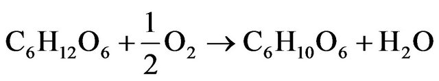 (1)
(1)
For such reaction, the value of the change of Gibbs energy (∆G) is equal to −251 [kJ/mol] (Kerzenmacher et al., 2008) and the process of glucose oxidation is spontaneous.
However, it is well known that reaction (1) is very slow at ambient condition. To increase the efficiency of this process the application of catalyst is required. As a catalyst material the metal nanoparticles [20-22] or enzyme can be used. In fact, in the literature there is a significant number of publications, containing information about potential application of sugar in alkaline fuel cells (AFC) [23-25]. It was also found that gold nanoparticles surface modified with glucose oxidase can be used as biosensor for detecting glucose [26].
The aim of this work was to investigate the electrooxidation properties of glucose catalyzed by gold nanoparticles deposited on graphene sheets. For this study glassy carbon (GC) electrode as a template for catalyst materials was used (surface area 0.196 cm2). To the best of our knowledge, it is the first time when gold nanoparticles on graphene sheets were synthesized in microflow reactor and used as the catalyst in glucose electrooxidation.
2. Experiments
Cyclic voltamperometry (CV) measurements were followed by nitrogen flushing through analyzed solution to remove oxygen from the sample (flushing time was about 15 min). Working electrode was prepared as follow: on freshly polished surface of glassy carbon electrode (polishing grain 0.05 µm—aluminium oxide), 20 µL of freshly prepared colloidal suspension was spread of GC and evaporated. All electro-catalytic studies were carried out at pH = 13 (in 0.1 M NaOH). Electrochemical characterizations were carried out using Autolab PGSTAT12 potentiostat-galvanostat. In all experiments 25 m∙Vs−1 scan rate and initial concentration of glucose of 10 mM was applied.
2.1. Chemicals
Gold (III) chloride complex ions solution was obtained by dissolving metallic gold (purity 99.99%) in aqua regia. An excess of nitric acid was evaporated. Obtained dry mass of HAuCl4 was dissolved in concentrated hydrochloride acid to remove trace of nitric acid. This step was repeated several times. Finally, pure tetrachloride aurate acid was dissolved in water to obtain solution of 0.1 M. This basic solution was later used in experiments after suitable dilution.
Graphene oxide was purchased from Graphene Supermarket®, as a dispersion in water (initial concentration 5 g/L). This liquid has brown color. According to the supplier specification, 60% of the dispersed mass has thickness of 1 atomic layer.
Dimethylaminoborane complex, DMAB, (supplied by Sigma-Aldrich >97%)) was used as a reducing agent. Glucoseused during catalytic properties studies of graphene sheets decorated with gold nanoparticles was obtained from Chempur (anhydrous, p.a).
2.2. Catalyst Preparation
Gold nanoparticles were synthesized by the chemical reduction of gold (III) salt in amicroflow reactor (details are given in paperin press). Inputs and outputs of the reactor channels are presented schematically in Figure 1. An aqueous solution containing gold (III) chloride ions at initial concentration of 5 × 10⁻⁴ M was mixed with a graphene oxide sheet (mass weight ratio: mGO/mAu = 1:1). In case of naked AuNPs synthesis, GO stream was replaced by water. The obtained solution was mixed with 5 × 10⁻³ M aqueous solution of DMAB in the proportion 2:1 (volumetric ratio). After less than 1 second colloidal gold was obtained and clear transparent solution changed the color to red. Flow rate of each reagent across of microreactor was maintained at 1 mL/min.
2.3. UV-Vis Spectrum
The suspensions obtained using the micro flow reactor was analyzed spectrophotometrically (Shimadzu model U-2501PC, Japan). The first spectrum (Figure 2—red color, solid line) was registered 5 minutes after gold nanoparticles had been prepared (without graphene oxide). The next spectrum (Figure 2—black color, dash line) was registered after gold chloride complex reduction in the presence of graphene oxide sheets.
2.4. Microscopy Analysis
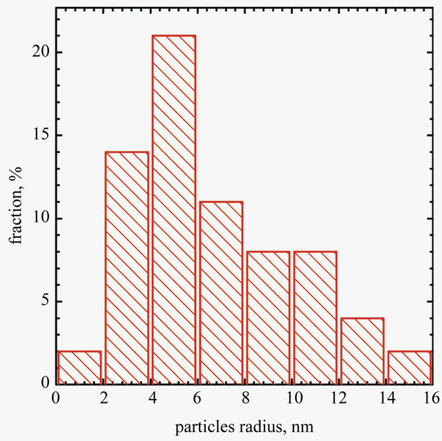
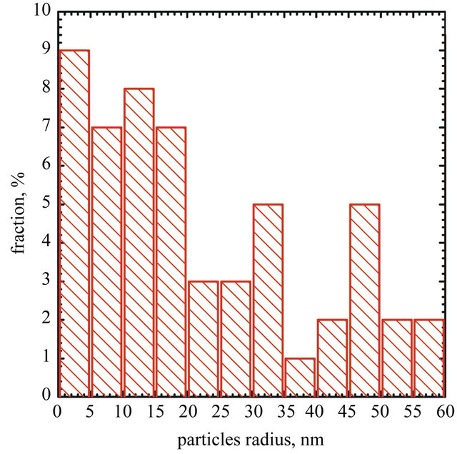
SEM analyses were carried out using Hitachi SU-70 microscope. One drop of Au concentrate (10 minutes after its preparation) was placed on a copper grid covered with a 20 - 30 nm carbon film, and next was left to dry at room temperature. The observations were performed also by transmission electron microscope (TEM) 24 h after preparation. Particles size and size distribution were determined using ImageJ application (ver. 1.46 r). The obtained results are shown in Figures 3 and 4.
Image of graphene sheet decorated with gold nanoparticles is shownin Figure 3. It can be seen that gold nano-
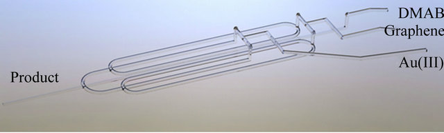
Figure 1. Microflow reactor applied in the synthesisof the catalyst.
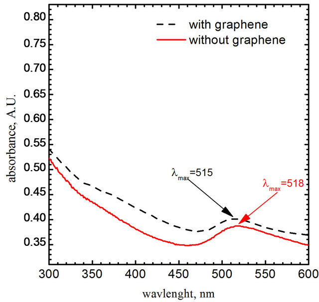
Figure 2. The UV-V is spectrums obtained for colloids as a result of a chemical Au (III) ions reduction with DMAB addition. The length of optical path l = 1 cm.
 (a)
(a)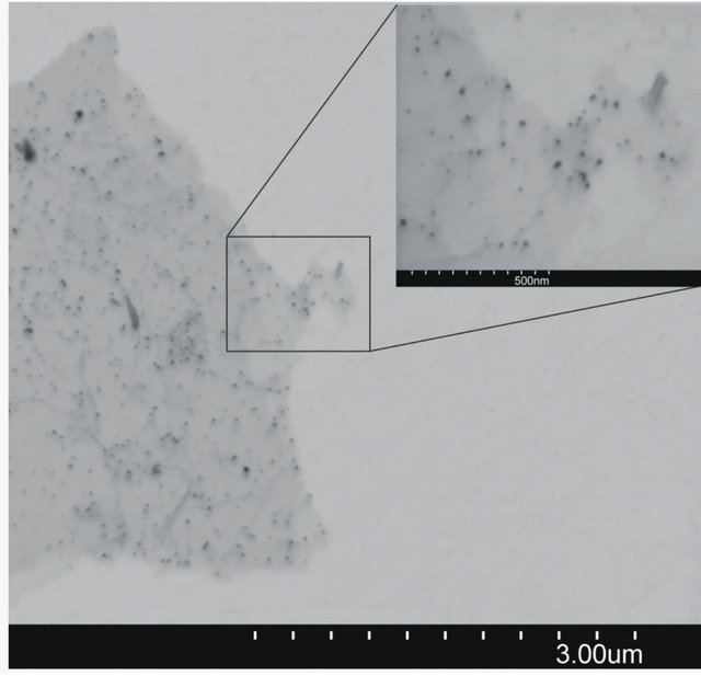 (b)
(b)
Figure 3. SEM micrograph of AuNPs deposited on graphene surface (b) and particles size distribiution (a).
 (a)
(a)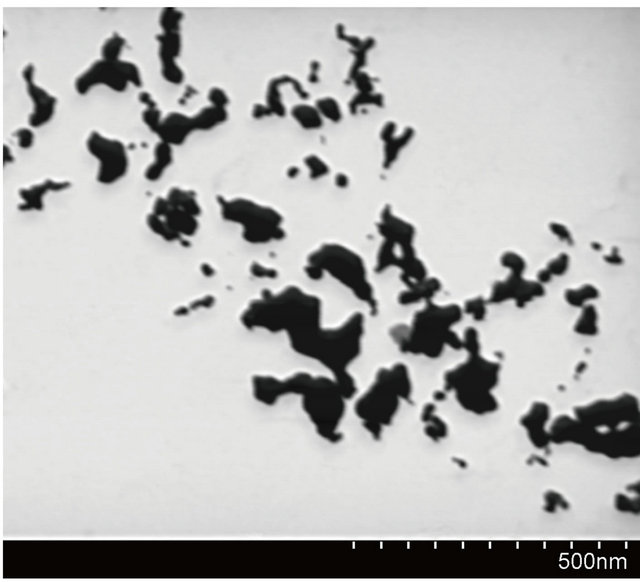 (b)
(b)
Figure 4. SEM image of AuNPs obtained without grapheme (b) and particles size distribiution (a).
particles are deposited only on graphene sheet surface. It suggests that the condition of experiments were suitable for single step reduction and deposition of gold nanoparticles on graphene oxide surface. Gold nanoparticles synthesized under the same conditions but without the addition of graphene oxide sheets are shown in Figure 4. In this case aggregation process of gold nanoparticles is observed.
2.4.1. HR STEM Analysis
The detailed structure investigations of the prepared material were carried out with high resolution Scanning Transmission Electron Microscope (STEM) Hitachi HD- 2700 (200 kV, Cs corrected). The high resolution observations showed that the size of gold particles is truly in nanorange, in good agreement with previous analyses. Also, it has been observed that some of Au nanoparticles show five-fold symmetry (Figure 5).
Five-fold symmetry was observed in small particles and quasi-crystals. That kind of symmetry has been
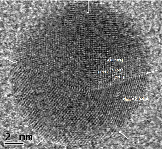
Figure 5. HR STEM image of Au nanoparticle with fivefold symmetry (twin planes are indicated by arrows).
reported [27,28] for face-centered cubic structures in the early stages of particle growth. Such symmetry in fcc structures results in a lattice along fivefold-axis and gives rise to the inner stresses in growing crystals The maximum size of five-fold particles without distortion has been reported [28] to be around 40 nm.
It is well known that the shape of gold particles of the size of a few nanometers shows morphologies which include cubeoctahedral, octahedral, truncated octahedral, icosahedral, pentagonal decahedral shapes and their twinned variants. A decahedral MTP (multiply twinned particles) can be described as the aggregate of five slightly distorted tetrahedra joined with a twinning relationship on their facets [29]. Thus the dihedral angle between two continuous tetrahedra is 72˚ instead of 70.5˚. The icosahedral MTP consists of 20 of such tetrahedra joined in the same way. So the generated gap of 7.5˚ among the tetrahedra induces significant strain generating dislocations and other structural defects.
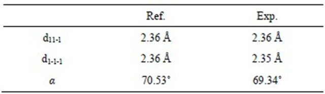
The HR STEM image of gold nanoparticle with fivefold symmetry is shown in Figure 5. The particle with the size of 12 nm has a round shape and five twin boundaries are indicated by arrows (which are better seen in HAADF STEM image—Figure 6(a)). One can observe disordered twin boundaries and other defects, such as dislocations (which are better seen on filtrated image —Figure 6(b)) and stacking faults. This image clearly shows that the five parts have twin relations at their boundaries. In this image, two dimensional lattice fringes with separations of 2.36 Å and 2.35 Å, which correspond to the lattice spacings of (11-1) and (1-1-1), respectively, are also visible. The angle between those lattices is equal to 69.34˚. The reference and experimental data are collected in Table 1.
HR STEM image of the center of the Au nanoparicle from Figure 5 where the twin boundaries and angles between units in particle with five-fold symmetry is shown in Figure 7.
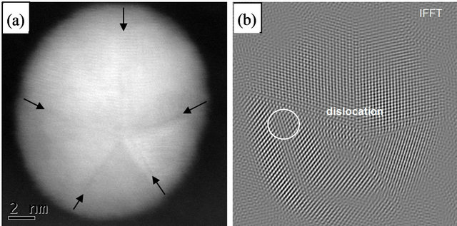
Figure 6. HAADF STEM image of Au nanoparticle with five-fold symmetry (a) (twin planes are indicated by arrows) and filtrated image of Figure 5(b).
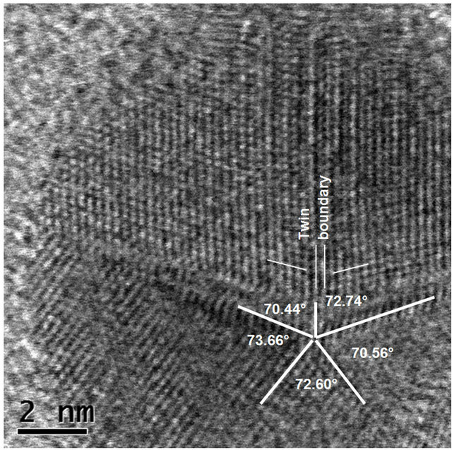
Figure 7. HR STEM image of the center of the Au nanoparicle from Figure 6: decahedral MTP (multiply twinned particles).
Table 1. Reference vs. experimental data.
2.4.2. Catalytic Properties Study
Electro-oxidation of glucose was investigated using the experimental setup shown schematically in Figure 8. As a reference electrode, saturated calomel electrode was used. As a counter electrode, platinum mash was applied.
First, cyclic voltammograms of pure GC electrode and GC covered by AuNPs deposited on graphene sheet were obtained only with base electrolyte, without glucose. Small peak at potential −0.01 V (Figure 9(b)) was observed which can be explained as caused by the traces of oxygen remaining in the solution adsorbed on AuNPs surface.
Next, to make sure that pure GC electrode did not catalyse oxidation of glucose, cyclic voltammogram in 10 mM of glucose solution was acquired.
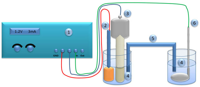
Figure 8. Scheme of the setup for electro-oxidation of glucose: 1-potentiostat, 2-reference electrode, 3-working electrode, 4- aqeous solution of glucose and sodium hydroxide, 5-salt bridge, 6-counter electrode.
−1.25 −1.00 −0.75 −0.50 −0.25 0.00 0.25 −1.25 −1.00 −0.75 −0.50 −0.25 0.00 0.25 potential vs. NEK, V potential vs. NEK, V
Figure 9. Cyclic voltammogram in 0.1 M NaOH, A-GC electrode without Au, B-GC electrode covered with gold nanoparticles decorated grapheme sheet.
These experiments (Figures 9(a), (b) and 10) showed no peak during cyclic voltammograms studies. It confirms that GC electrode is inert in system of interest.
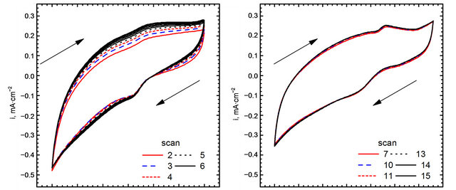
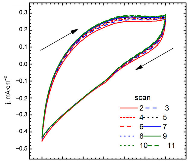
Cyclic voltammograms of electro-oxidation of glucose are shown in Figure 11 (scan direction indicated by arrows). It can be noted that independently of kind of catalyst used in the experiments three peaks were observed. For GC-gold catalyst (Figure 11(b)) first peak was observed at the potential −0.42 V. Location of this peak agrees with the results obtained by Feng [30] who performed experiments in 0.1 M NaOH using gold nanoparticle-chitosan composite film as a catalyst. Pasta and co-workers [25,31], suggested that this peak can be attributed to dehydrogenation of anomeric carbon, in good agreement with the results of Basu et al. [24].
Second peak was observed at the potential 0.22 V. Also in this case the location of the peak is in good agreement with the results obtained by Feng [30]. Pasta et al. suggested that long left shoulder of this voltammograms corresponds to several different processes taking place at similar potentials. In our opinion it is an effect of superposition two processes: an adsorption of oxygen traces dissolved in the base electrolyte (Figure 8(b)), and further oxidation of gluconolactone generated during glucose electro-oxidation in first step [30].
It can be seen, that the application of Au-graphene catalyst changes significantly CV curves. First, a shift of the peaks can be observed. For the points “a” and “a’” this shift is equal to 0.06 V, while for “b” and “b’”— equal to 0.03 V. A remarkably high shift can be observed for points “c” and “c’”—from 0.18 to 0.09 V. The changes in peak positions are accompanied by changes in
−1.25 −1.00 −0.75 −0.50 −0.25 0.00 0.25 0.50 Potential vs. NEK, V
Figure 10. Cyclic voltammograms in 0.1 M NaOH and 10 mM glucose, without AuNPs.
current density. These changes, however, can be evaluated only after adjusting for the variable size distribution of nanogold particles. To this end, surface area of gold nanoparticles was calculated for the experimentally determined particles size distributions and assuming their spherical shape. The number of particles with the radius R can be calculated using Equation (2)
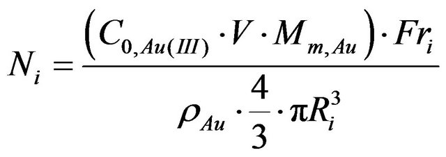 (2)
(2)
where:
Ni—Number of particles in Ri radius;
Mm,Au—Molarmassof gold;
C0,Au(III)—Initial concentration of gold salt;
V—Value of suspension used in synthesis of electrode (in this case 20 µL);
ρAu—Gold density for fcc structure (19.3 g/cm3) [32];
Ri—Radius of “i” fraction of gold nanoparticles;
Fri—Fraction of gold nanoparticles in %.
The number of particles as a function of their radius can be used to determine surface area of the electrode taking into account size distribution of those particles, as follows:
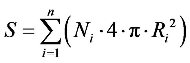 (3)
(3)
It was found that surface area of AuNPs-GO is equal to 13 × 10−3 m2 and 5.7 × 10⁻³ m2 for naked AuNPs. Truly surface area of AuNPs-GO in compare to naked AuNPs is about 2.3 times higher, respectively. It seems that graphene plays an important role as stabilizing agent for gold nanoparticles.
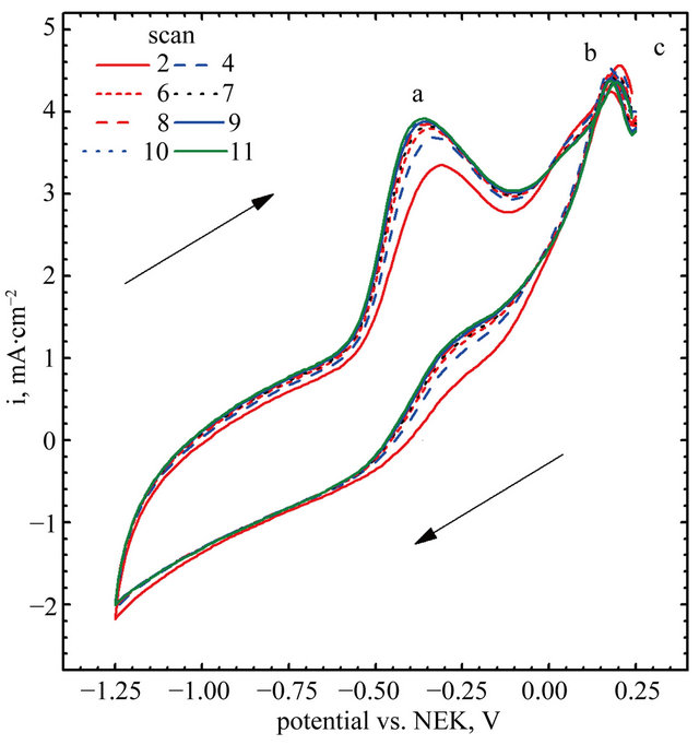
(A)
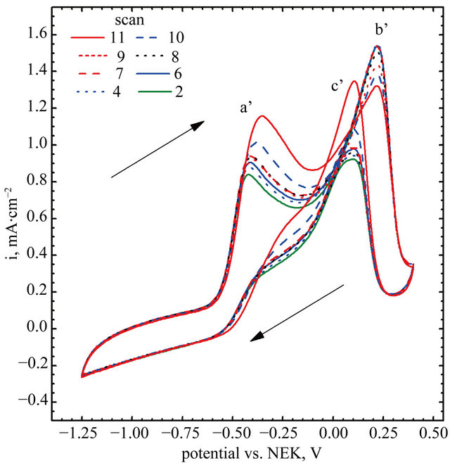
(B)
Figure 11. Electro-oxidation of glucose, (A) gold nanoparticles decorated graphene sheet; (B) Naked gold nanoparticles.
3. Conclusions
Glucose electro-oxidation may have potential applications in several fields e.g. medicine for glucose measurements in blood, power engineering in fuel cells and in the chemical industry for gluconic acid and other chemicals production.
In this study we showed that synthesis of graphenegold catalyst leads to the formation of a new kind of catalyst which is more active that its standard counterpart. Apparent current density of the glucose oxidation, increases from 1.16 mA/cm2 up to 3.82 mA/cm2 (in respect to GC surface area). However, taking into account differences in the particles size and size distribution, truly surface area of catalyst is equal to 13 × 10−3 m2 for AuNPs-GO and 5.7 × 10⁻³ m2 for naked AuNPs. Taking it into account oxidation current density on gold-graphene catalyst is about 31% higher than on naked AuNPs. It may suggest that gold nanoparticles size influences catalytic properties, but it cannot be excluded, that graphene also plays an important role during this oxidation process.
4. Acknowledgements
The authors gratefully acknowledge for financial support from AGH University of Science and Technology (contract No. 11.11.180.373.2011), and European Grant No. POIG.01.01.02.-00-015/09-00.
REFERENCES
- S. Stankovich, R. D. Piner, X. Chen, N. Wu, S. T. Nguyen and R. S. Ruoff, “Stable Aqueous Dispersions of Graphitic Nanoplatelets via the Reduction of Exfoliated Graphite Oxide in the Presence of Poly(Sodium 4-Styrenesulfonate),” Journal of Materials Chemistry, Vol. 16, 2006, pp. 155-158.
- M. Hirata, T. Gotou, S. Horiuchi, M. Fujiwara and M. Ohba, “Thin-Film Particles of Graphite Oxide 1: HighYield Synthesis and Flexibility of the Particles,” Carbon, Vol. 42, No. 14, 2004, pp. 2929-2937.
- S. Stankovich, R. D. Pine, S. T. Nguyen and R. S. Ruoff, “Synthesis and Exfoliation of Isocyanate-Treated Graphene Oxide Nanoplatelets,” Carbon, Vol. 44, No. 15, 2006, pp. 3342-3347.
- B. C. Brodie, “On the Atomic Weight of Graphite,” Philosophical Transactions, Vol. 149, 1859, pp. 249-259.
- W. Hummers and R. Offeman, “Preparation of Graphitic Oxide,” Journal of the American Chemical Society, Vol. 80, No. 6, 1958, pp. 1339-1339. doi:10.1021/ja01539a017
- Á. Mastalira, Z. Királyb, Á. Patzkób, I. Dékányb and P. L’Argentierec, “Synthesis and Catalytic Application of Pd Nanoparticles in Graphite Oxide,” Carbon, Vol. 46, No. 13, 2008, pp. 1631-1637.
- B. Hvolbæk, T. V. W. Janssens, B. S. Clausen, H. Falsig, C. H. Christensen and J. K. Nørskov, “Catalytic Activity of Au Nanoparticles,” Nanotoday, Vol. 2, No. 4, 2007, pp. 14-18. doi:10.1016/S1748-0132(07)70113-5
- J. Hernández, J. Solla-Gullón, E. Herrero, A. Aldaz and J. M. Feliu, “Methanol Oxidation on Gold Nanoparticles in Alkaline Media: Unusual Electrocatalytic Activity,” Electrochemica Acta, Vol. 52, No. 4, 2006, pp. 1662-1669.
- I.-S. Park, K.-S. Lee, D.-S. Jung, H.-Y. Park and Y.-E. Sung, “Electrocatalytic Activity of Carbon-Supported PtAu Nanoparticles for Methanol Electro-Oxidation,” Electrochemica Acta, Vol. 52, No. 18, 2007, pp. 5599-5605.
- G. J. Hutchings, S. Carrettin, P. Landon, J. K. Edwards, D. Enache, D. W. Knight, Y.-J. Xu and A. F. Carley, “New Approaches to Designing Selective Oxidation Catalysts: Au/C a Versatile Catalyst,” Topics in Catalysis, Vol. 38, No. 4, 2006, pp. 223-230. doi:10.1007/s11244-006-0020-y
- D. Geng and G. Lu, “Size Effect of Gold Nanoparticles on the Electrocatalytic Oxidation of Carbon Monoxide in Alkaline Solution,” Journal of Nanoparticle Research, Vol. 9, No. 6, 2007, pp. 1145-1151.
- D. A. Bulushev, I. Yuranov, E. I. Suvorova, P. A. Buffat and L. Kiwi-Minsker, “Highly Dispersed Gold on Activated Carbon Fibers for Low-Temperature CO Oxidation,” Journal of Catalysis, Vol. 224, No. 1, 2004, pp. 8-17.
- E. Mohammad and M. Norita, “Electrooxidation of Ethylene Glycol Using Gold Nanoparticles Electrodeposited on Pencil Graphite in Alkaline Medium,” Science China Chemistry, Vol. 55, No. 2, 2012, pp. 247-255. doi:10.1007/s11426-011-4402-z
- M. Luty-Błocho, K. Fitzner, V. Hessel, P. Löb, M. Maskos, D. Metzke, K. Pacławski and M. Wojnicki, “Synthesis of Gold Nanoparticles in an Interdigital Micromixer Using Ascorbic Acid and Sodium Borohydride as Reducers,” Chemical Engineering Journal, Vol. 171, No. 1, 2011, pp. 279-290.
- B. Streszewski, W. Jaworski, K. Pacławski, E. Csapó, I. Dékány and K. Fitzner, “Gold Nanoparticles Formation in the Aqueous System of Gold(III) Chloride Complex Ions and Hydrazine Sulfate—Kinetic Studies,” Colloids and Surfaces A, Vol. 397, 2012, pp. 63-72.
- M. A. Montero, M. R. G. de Chialvo and A. C. Chialvo, “Preparation of Gold Nanoparticles Supported on Glassy Carbon by Direct Spray Pyrolysis,” Journal of Materials Chemistry, Vol. 20, 2009, pp. 3276-3280.
- F. Mafune, J. Kohno, Y. Takeda and T. Kondow, “Formation of Gold Nanoparticles by Laser Ablation in Aqueous Solution of Surfactant,” The Journal of Physical Chemistry B, Vol. 22, No. 105, 2001, pp. 5114-5120. doi:10.1021/jp0037091
- L. H. Bac, J. S. Kim and J. C. Kim, “Size, Optical and Stability Properties of Gold Nanoparticles Synthesized by Electrical Explosion of Wire in Different Aqueous Media,” Reviews on Advanced Materials Science, Vol. 28, 2011, pp. 117-121.
- P. K. Jain, K. S. Lee, I. H. El-Sayed and M. A. El-Sayed, “Calculated Absorption and Scattering Properties of Gold Nanoparticles of Different Size, Shape and Composition: Applications in Biological Imaging and Biomedicine,” The Journal of Physical Chemistry B, Vol. 110, No. 14, 2006, pp. 7238-7248.
- I. T. Bae and E. Yeager, “In Situ Infrared Studies of Glucose Oxidation on Platinum in an Alkaline Medium,” Journal of Electroanalytical Chemistry and Interfacial Electrochemistry, Vol. 309, No. 1-2, 1991, pp. 131-145. doi:10.1016/0022-0728(91)87009-S
- J. M. H. Dirkx and H. S. van der Baan, “The Oxidation of Glucose with Platinum on Carbon as Catalyst,” Journal of catalysis, Vol. 67, No. 1, 1981, pp. 1-13. doi:10.1016/0021-9517(81)90256-6
- S. Karski, T. Paryjczak, J. Rynkowski and I. Witońska, “Catalytic Oxidation of Glucose on Supported Palladium Catalysts,” Polish Journal of Chemical Technology, Vol. 2, No. 1, 2000, pp. 10-13.
- J. Chen, C. X. Zhao, M. M. Zhi, K. Wang, L. Deng and G. Xu, “Alkaline Direct Oxidation Glucose Fuel Cell System Using Silver/Nickel Foams as Electrodes,” Electrochimica Acta, Vol. 66, 2012, pp. 133-138.
- D. Basu and S. Basu, “A Study on Direct Glucose and Fructose Alkalinefuelcell,” Electrochimica Acta, Vol. 55, No. 20, 2010, pp. 5775-5779. doi:10.1016/j.electacta.2010.05.016
- M. Pasta, R. Ruffo, E. Falletta, C. M. Mari and C. D. Pina, “Alkaline Glucose Oxidation on Nanostructured Gold Electrodes,” Gold Bulletin, Vol. 43, No. 1, 2010, pp. 57- 64. doi:10.1007/BF03214967
- S. Zhao, K. Zhang, Y. Bai, W. Yang and C. Sun, “Glucose Oxidase/Colloidal Gold Nanoparticles Immobilized in Nafion Film on Glassy Carbon Electrode: Direct Electron Transfer and Electrocatalysis,” Bioelectrochemistry, Vol. 69, No. 2, 2006, pp. 158-163.
- S. Ogawa and S. Ino, “Formation of Multiply-Twinned Particles on Alkali Halide Crystals by Vacuum Evaporation and Their Structures,” Journal of Crystal Growth, Vol. 13-14, No. 48-56, 1972, p. 48.
- T. Oku and K. Hiraga, “Atomic Structures and Stability of Hexagonal BN, Diamond and Au Multiply-Twinned Nanoparticles with Five-Fold Symmetry,” Diamond and Related Materials, Vol. 10, No. 3-7, 2000, pp. 1398-1403.
- H. P. Boehm, “Surface Oxides on Carbon and Their Analysis: A Critical Assessment,” Carbon, Vol. 40, No. 2, 2002, pp. 145-149.
- D. Feng, F. Wang and Z. Chen, “Electrochemical Glucose Sensor Based on One-Step Construction of Gold Nanoparticle-Chitosan Composite Film,” Sensors and Actuators B: Chemical, Vol. 139, No. 2, 2009, pp. 539-544.
- M. Pasta, F. L. Mantia and Y. Cuib, “Mechanism of Glucose Electrochemical Oxidation on Gold Surface,” Electrochemica Acta, Vol. 55, No. 20, 2010, pp. 5561-5568.
- X. Liu, M. Atwater, J. H. Wang and Q. Huo, “Extinction Coefficient of Gold Nanoparticles with Different Sizes and Different Capping Ligands,” Colloids and Surfaces B: Biointerfaces, Vol. 58, No. 1, 2007, pp. 3-7. doi:10.1016/j.colsurfb.2006.08.005
NOTES
*Corresponding author.