Natural Science
Vol.5 No.1(2013), Article ID:26624,5 pages DOI:10.4236/ns.2013.51009
Effect of doping concentration on the performance of solar cell constructed from (Muscovite/TiO2/Dye/Al)
![]()
1Department of Physics, Faculty of Science, Sudan University of Science and Technology, Khartoum, Sudan
2Department of Physics, Faculty of Education, Al-Zaiem Al-Azhari University, Om Durman, Sudan; mahmoudhilo@gmail.com
3Department of Physics, Faculty of Science and Arts at Al-Rass, Qassim University, Buraydah, KSA; mhhlo@qu.edu.sa
Received 17 March 2012; revised 20 April 2012; accepted 7 May 2012
Keywords: Solar Cell; Conductivity; Fill Factor; Efficiency; Muscovite
ABSTRACT
Solar cells were fabricated from (Muscovite/TiO2/ Dye/Al), the effect of temperature, concentration and light intensity on the electrical properties of (Muscovite/TiO2/Dye/Al) was studied. The relationship between current and voltage was found to be algorism, which is in agreement with the ordinary relation for solar cells. When dye concentration was increased the conductivity, fill factor and efficiency were also increased. This result is found to be in conformity with the theoretical relations. The small energy gaps for their samples show that they are semiconductors. The maximum efficiency obtained is 33.2%.
1. INTRODUCTION
Since the discovery of the conducting property of dye sensitized solar cell (DSSC), the field has been an active research area. The research activities have covered a wide range of electrical and optical properties and up to electronic properties of these devices. Moreover, some applications have been tried at the beginning of 1990’s, i.e. light-emitting diodes, sensors, field effect-transistor and solar cells [1]. In all these research activities, metal/ TiO2/dye junction played a significant role. However, few works have been reported on the fundamental properties of photovoltaic cells that have metal/TiO2/dye interfaces. Most photovoltaic cells that have been fabricated have low efficiency and high cost for example, Recent Advance in Dye sensitized Solar Cells, shows that the highest efficiency obtained is (η = 11.2%) [2], for Interface Engineering Solid-state Dye-sensitized Solar Cells (η = 1.7% ± 0.04%) [3], for Hybrid Organic Dyes Sensitized Solar Cells (η = 0.028%) [4], High-performance dye-sensitized solar cells based on solvent-free electrolytes produced from eutectic melts (η = 8.2 and less than 11%) [5]. Highly ordered TiO2 nano tubes were successfully fabricated using a nano porous alumina templating method, a modified sol gel route was used to infiltrate the alumina pores with Ti (OC3H7)4 which was subsequently converted into TiO2 nano tubes, the average external diameter, tube lengths, and wall thickness achieved were 295 nm, 6 - 15 µm, and 21 - 42 nm, respectively. Diffraction data reveals that the nano tubes consist solely of the anatase phase. Dye-sensitized solar cells using TiO2 nano tube arrays as the working electrode yielded power conversion efficiencies as high as 3.5% with a maximum incident photon-to-current conversion efficiency of 20% at 520 nm [6]. Dye-sensitized solar cells (DSSCs) made from oriented, one-dimensional semiconductor nanostructures such as nano rods, nano wires, and nano tubes are receiving attention because direct connection of the point of photo generation with the collection electrode using such structures may improve the cell performance, specifically, oriented single-crystalline TiO2 nano rods or nano wires on a transparent conductive substrate would be most desirable, but achieving these structures has been limited by the availability of synthetic techniques [7]. In this study, a facile, hydrothermal method was developed for the first time to grow oriented, single-crystalline retile TiO2 nano rod films on transparent conductive fluorine-doped tin oxide (FTO), and Efficient light harvesting by using green an-porphyrin-sensitized nano crystalline TiO2 films (η = 7.1%) [8] etc.
In searching for an optimal efficiency and low cost of a photovoltaic cell, this work investigates the properties of the TiO2/dye/Al junction. The study includes exploring the photovoltaic properties of the dye blended with TiO2 sandwiched between TiO2 and Al electrodes. The electrical properties of these cell thus made are analyzed from the study of current-voltage characteristics. The photovoltaic properties of the cell fabricated, are analyzed by exploring their power conversion efficiencies, fill factors, open-circuit-voltage, short-circuit-current, as well as the effect of incident light intensities on the output. This study has been motivated by the marvelous properties of the dye and blended with TiO2. These materials can be tuned, during synthesis, to match the visible region of solar spectrum. They have relatively higher absorption coefficients for the large parts of the sunlight spectrum. They are relatively less expensive, easy to handle at ambient conditions and large flexible films can be made from these materials. Thus, these materials are believed to be a potential source for future photovoltaic cells [9].
The study is directed towards the search for an optimal photovoltaic cell by the investigating the photovoltaic properties of the devices fabricated as single layer dye and TiO2. This leads to:
1) Improve the economic performance of PV systems in developing countries by reducing the cost and increasing the efficiency.
2) Fabricate and characterize of Muscovite/TiO2/Dye/ Al solar cells using the technique of physical vapor deposit (PVD).
In this paper, Section 2 is devoted for the working principle of the solar cell. Materials, the experimental work and sample preparation are exhibited in Sections 3, 4 and 5 respectively. Results, discussion and conclusion are presented in Sections 6, 7 and 8 respectively.
2. WORKING PRINCIPLE OF A SOLAR CELL
The behavior of a solar cell is displayed by plotting the current-voltage characteristic as in Figure 1.
The ratio between Isc and Voc called characteristic resistance
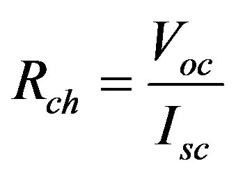 (1)
(1)
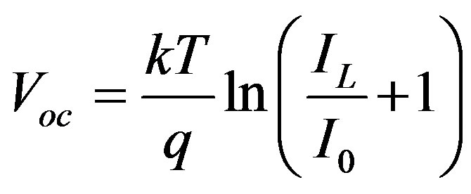 (2)
(2)
Where  = Constant, IL = Light generation current and
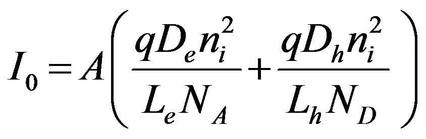 (Saturation Current)
The maximum power 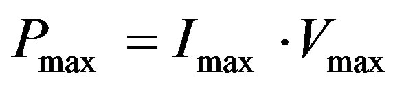
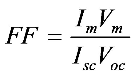
The ratio
 (3)
(3)
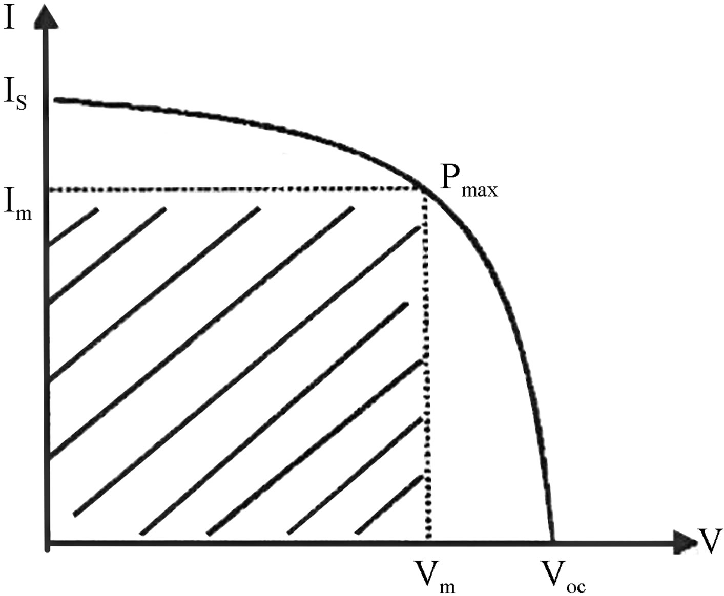
Figure 1. Current Voltage Relation.
Is called the fill factor (FF) of the cell.
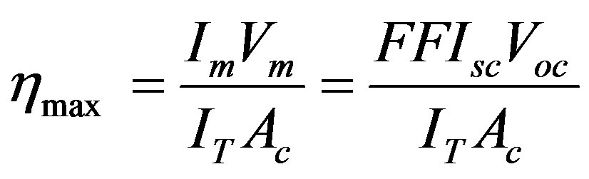
The maximum conversion efficiency of a solar cell is given by the ratio
 (4)
(4)
Where IT = incident solar flux and Ac = area of the cell [10].
3. MATERIALS
Titanium dioxide (TiO2) is a multifaceted compound. Titanium dioxide is a fascinating low-cost material exhibiting unique properties of stability and photo activity. It is useful for practical applications in areas such as the preparation of hybrid organic/TiO2 materials or as thermo labile devices substrates. Titanium oxide is also used as a semiconductor.
Dye-sensitized semiconductor systems were recently introduced as alternatives to conventional semiconductor materials in solar cells. Additional applications are in photo catalysis, sensors etc. A thin film of a nanostructure wide band gap semiconductor (only absorbing UVlight), typically TiO2, SnO2, or ZnO, sensitized to visible light by an organic dye molecule or other sensitizer is the key component of the system. Light absorption by the sensitizer initiates electron transfer from the semiconductor to the sensitizer, where free electrons can be harvested as current (solar cell), used for redox actions (catalysis), or constitutes an electrical impulse (sensor). Rhodamine B is a family of related chemical compounds, fluorine dyes. It is used as a dye and as a dye laser gain medium. Molecular Formula .
.
Mica Group is a complexity of alumina silicate that consists of potassium, magnesium, iron (Fe). Mostly, mica is found in Granite Rhyolite, Phyllite or Mica Schist (Muscovite or white mica, formula KAl2 (AlSi3O10) (OH)2).
4. THE EXPERIMENTAL WORK
0.35 g of the rhodamine B dye was weighed and dissolved in 25 ml ethanol. 0.1 g of TiO2 and a fusion mixture composed of 1 g of sodium-carbonate and 0.8 g of ammonium sulphate were weighed and mixed by a glass rod in a porcelain crucible and put into an electric furnace for 2:30 hours at 1200˚C. After cooling the content of crucible were dissolved with dilute sulphate acid. It was then heated to boiling till the contents were completely dissolved and then the solution was cooled and the volume was completed to 100 ml with distilled water in a volumetric flask.
5. SAMPLE PREPARATION
The samples were prepared by 0.05 g of TiO2 solution. The prepared solution was spin coated on the mica substrate for 60 sec and prepared by 0.35 g of rhodamine B dye solution. This solution was divided into three portions doped with iodine for three concentrations 0.05 g, 0.1 g, and 0.2 g. The prepared four concentrations solution were spin coated on the mica substrate at about 600 revolution per minute (rpm) for 60 sec in order to yield a thin uniform film. Finally aluminum strips were evaporated on top of the (Muscovite/TiO2/Dye) sensitize at a pressure of 1 × 10⁻⁶ mbar, using Coating Unit. The thin film was placed in the sample holder of UV Spectrophotometer (UV 1240) with help of ultra-violet computer, the absorption spectrum was obtained. These samples (9 samples) were connected in serial circuit with nanometer, voltmeter and rheostat. The measurements were taken at different room temperatures (300 K, 303 K). I-V measurement in dark and under illumination was carried out by mounting the sample in a sample holder metal, having area about 1 cm2. The current was measured using NanoAmpere meter and voltage measured using multi meter device. The intensity of the incident light was measured (0.2 and 0.4 W/m2) using a light meter. Michelson interferometer was used for thickness measurement of (Muscovite/TiO2/Dye/Al) layer which is coated on a mica substrate.
6. RESULTS
Current-Voltage plots are very useful in identifying the conduction mechanism as well as in evaluating the solar cell parameters, such as the cell efficiency, fill factor, the characteristic resistance and current density (J). The open voltage value Voc short circuited current Isc, and the shunt resistance are obtained from Figures 2-10 beside Eqs.1, 2, 3 and 4.
7. DISCUSSION
The (I vs. V) characteristics for the nine samples show exponential relation between voltage (V) and current (I). These relations are in conformity with the theoretical
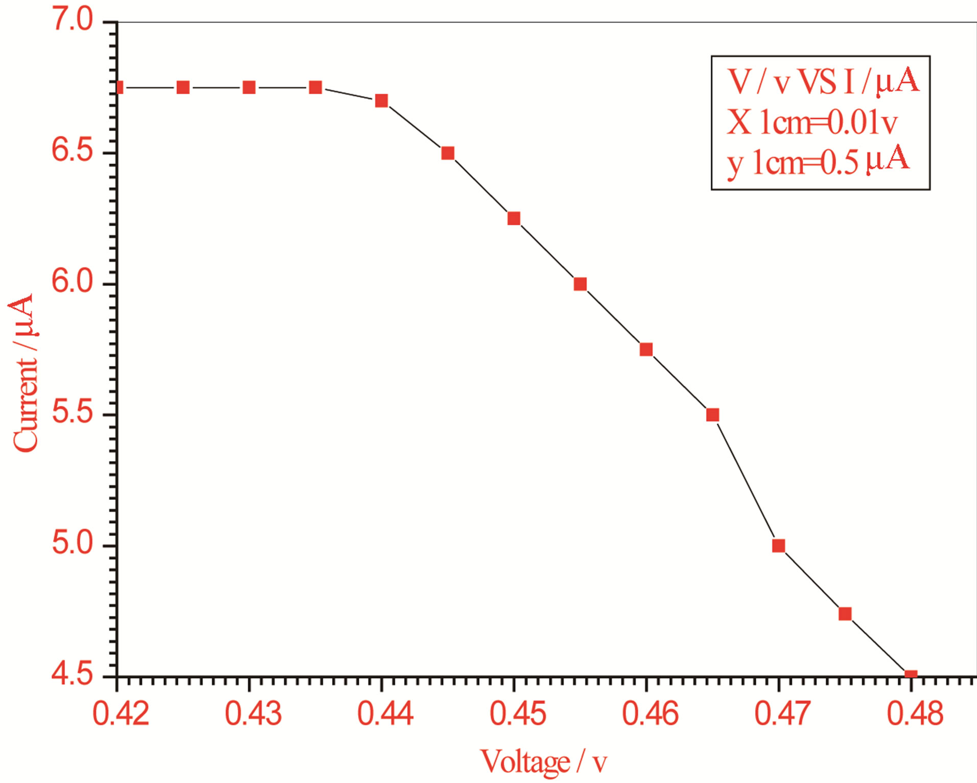
Figure 2. Relation between voltage and current for (Muscovite/TiO2/Dye/Al) (0.05 g concentration-600 rpm-300 k).
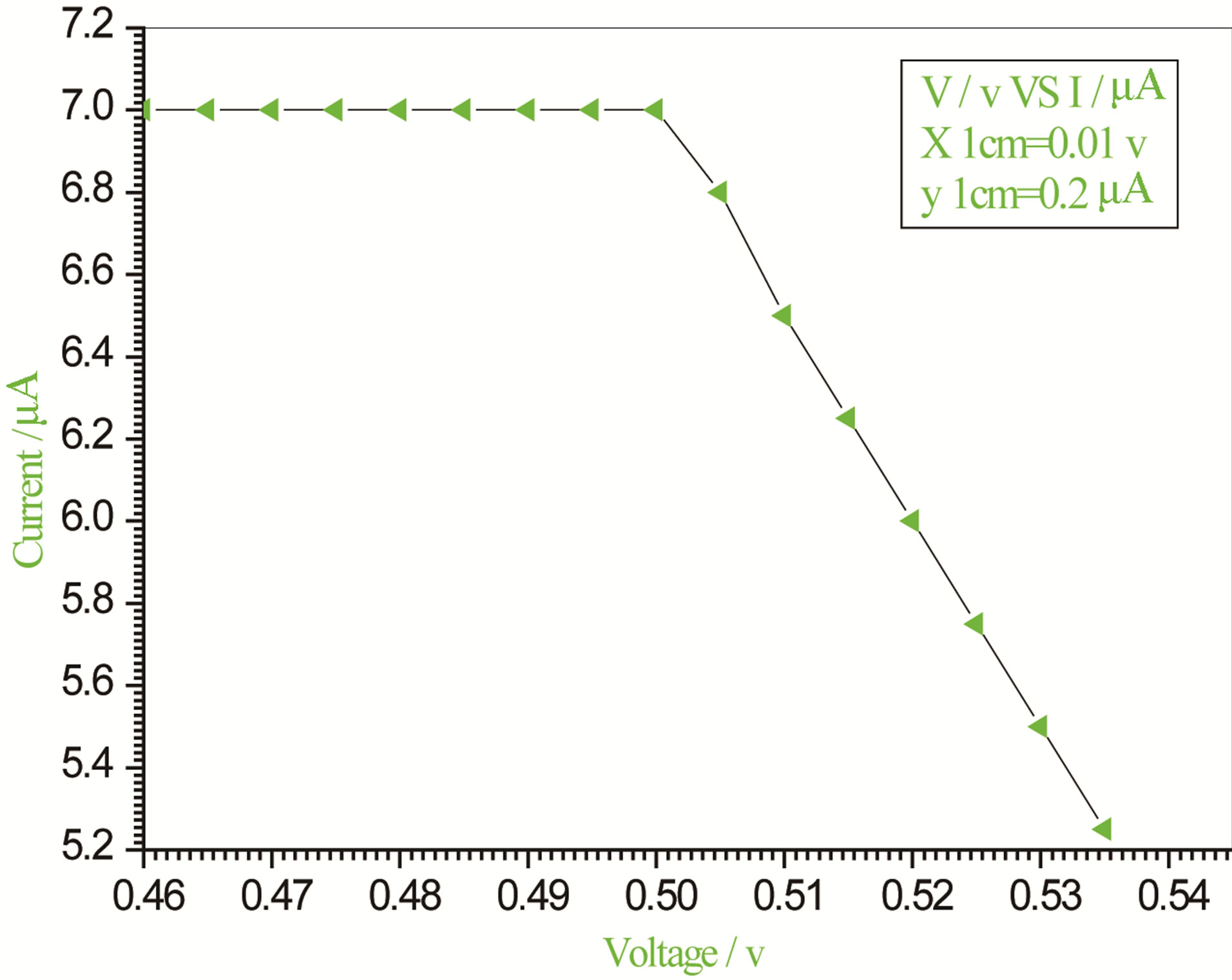
Figure 3. Relation between voltage and current for (Muscovite/TiO2/Dye/Al) (0.05 g concentration-700 rpm-300 K).
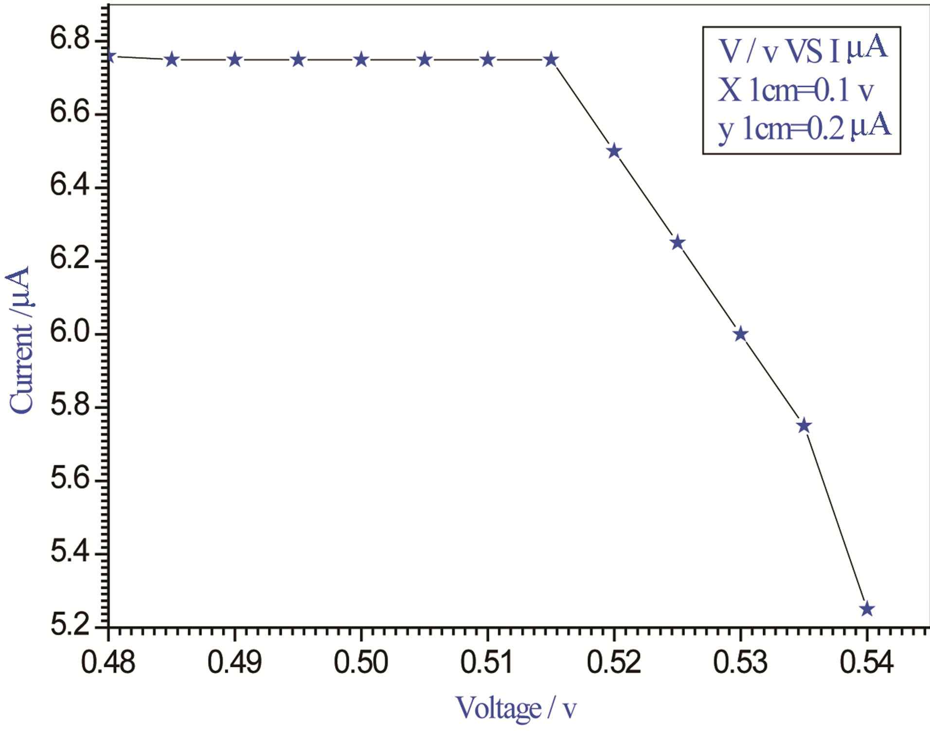
Figure 4. Relation between voltage and current for (Muscovite/TiO2/Dye/Al) (0.05 g concentration-800 rpm-300 K).
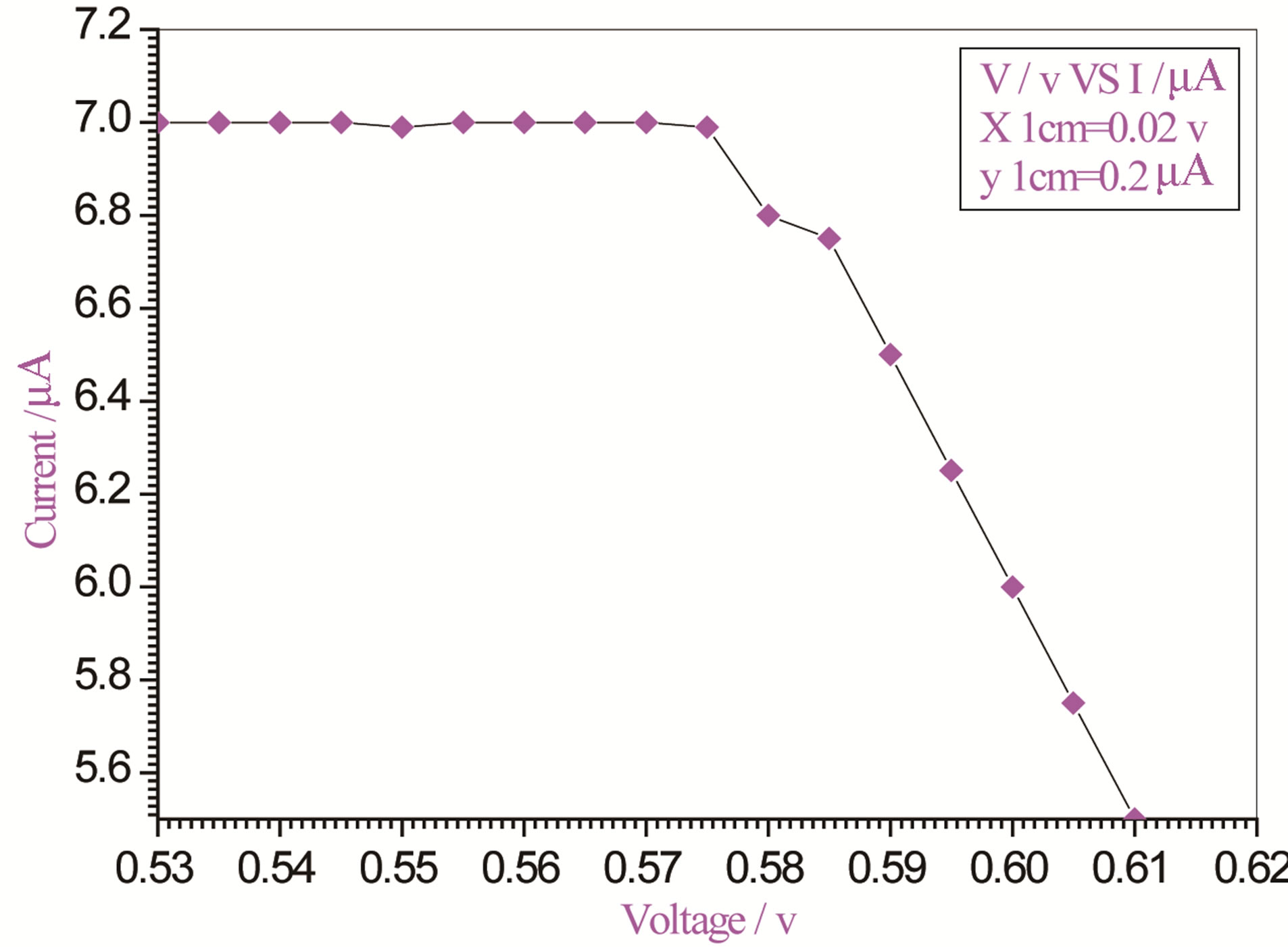
Figure 5. Relation between voltage and current for (Muscovite/TiO2/Dye/Al) (0.1 g concentration-600 rpm-300 K).
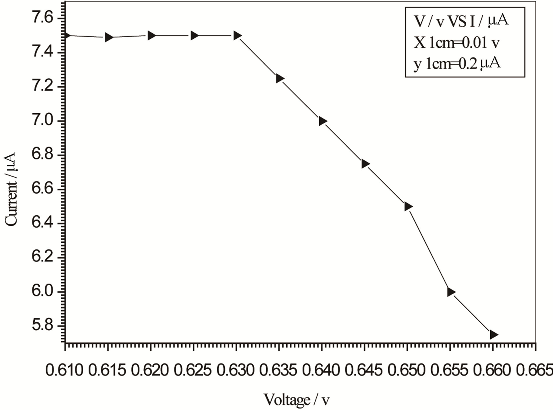
Figure 6. Relation between voltage and current for (Muscovite/TiO2/Dye/Al) (0.1 g concentration-700 rpm-300 K).
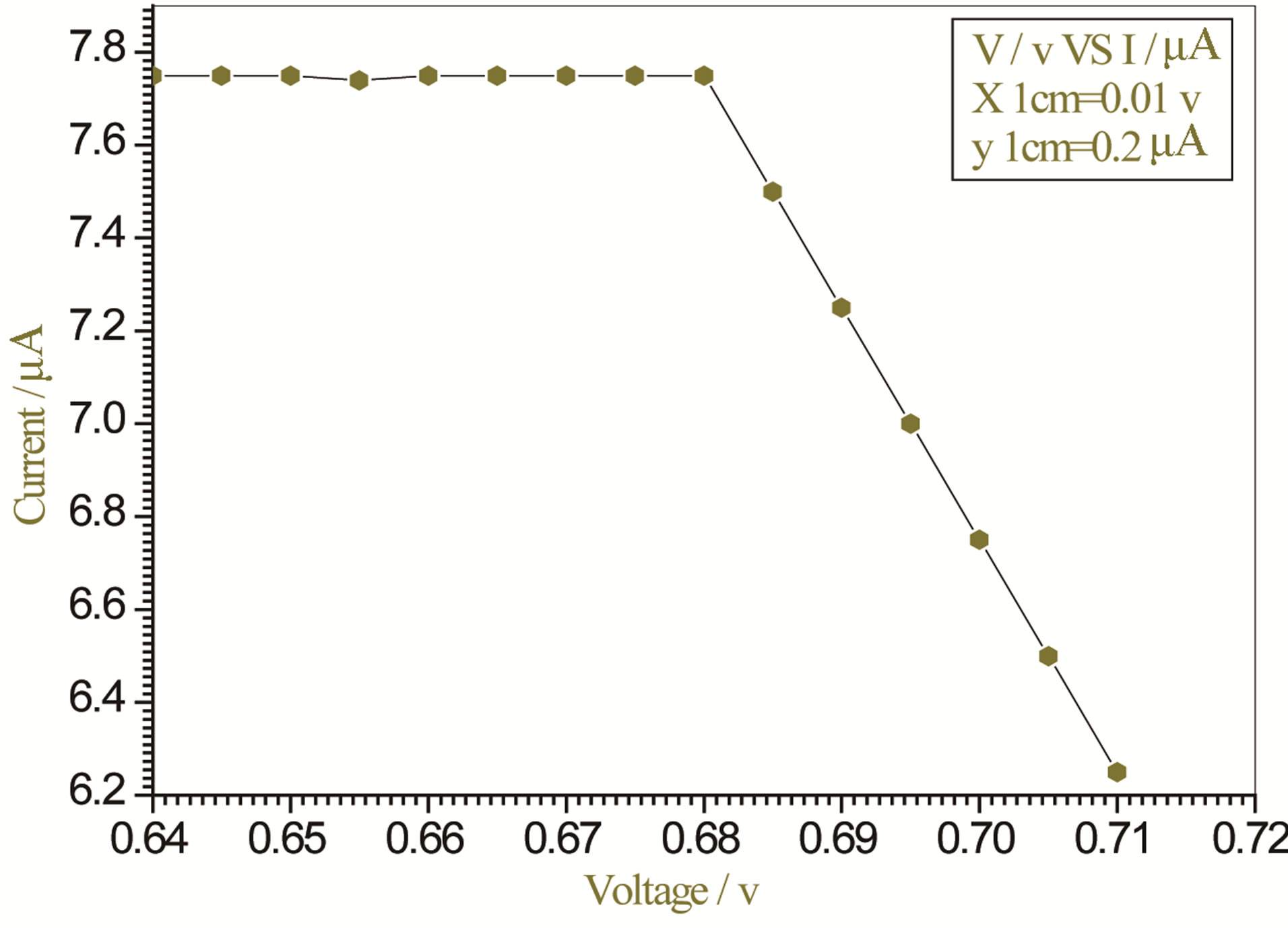
Figure 7. Relation between voltage and current for (Muscovite/TiO2/Dye/Al) (0.1 g concentration-800 rpm-300 K).
relation  (1), and with the empirical
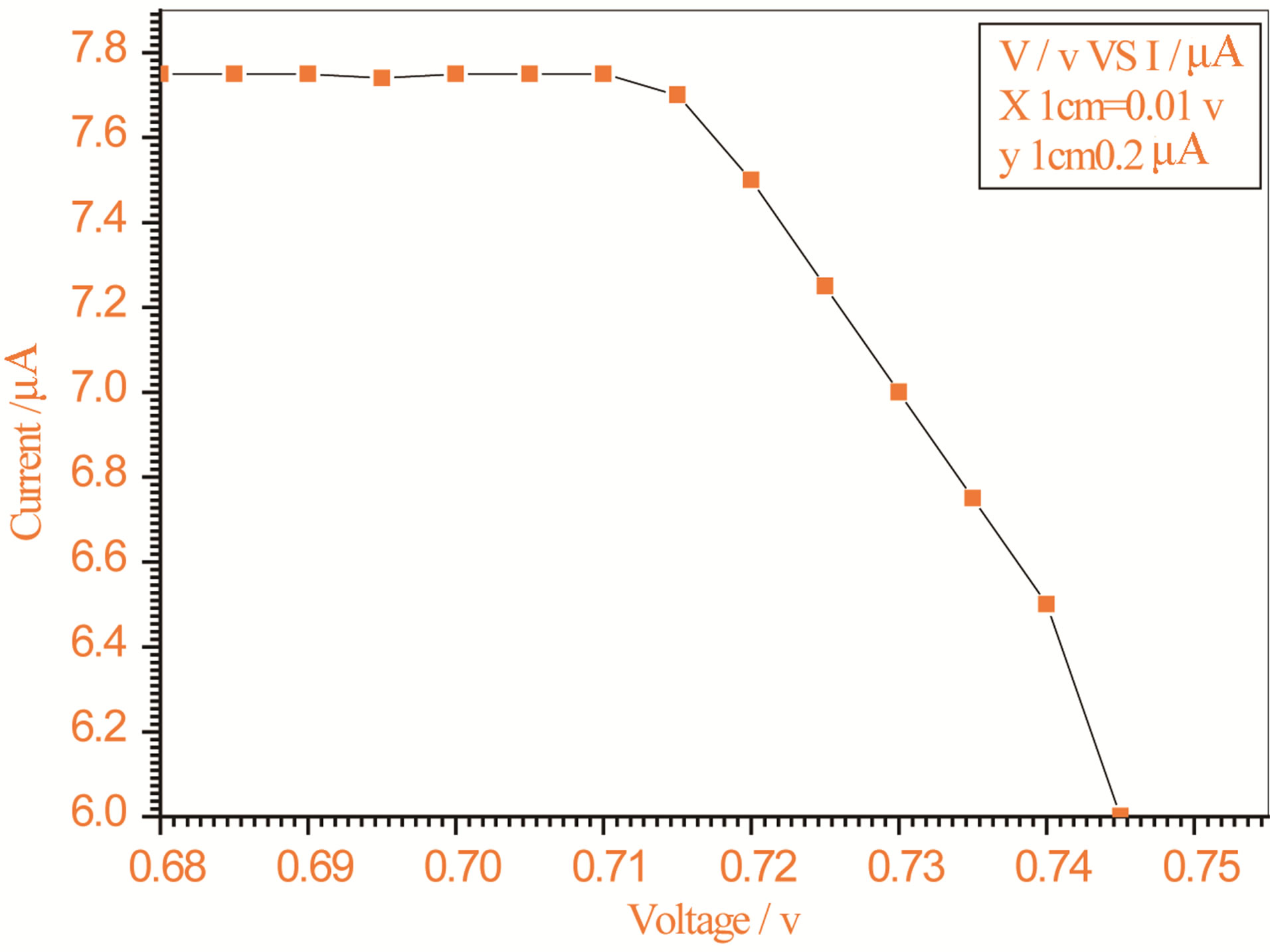
Figure 8. Relation between voltage and current for (Muscovite/TiO2/Dye/Al) (0.2 g concentration-600 rpm-300 K).
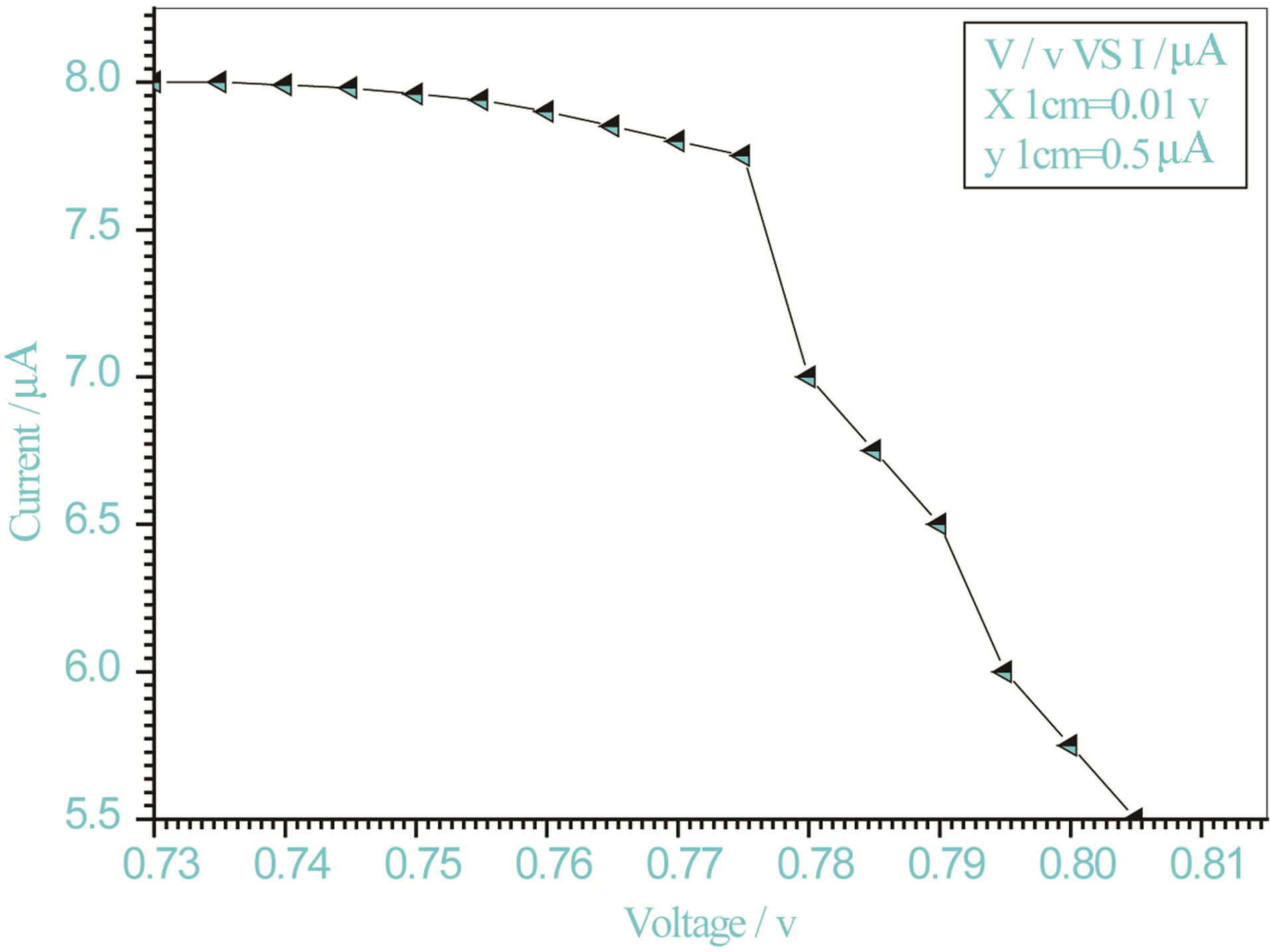
Figure 9. Relation between voltage and current for (Muscovite/TiO2/Dye/Al) (0.2 g concentration-700 rpm-300 K).
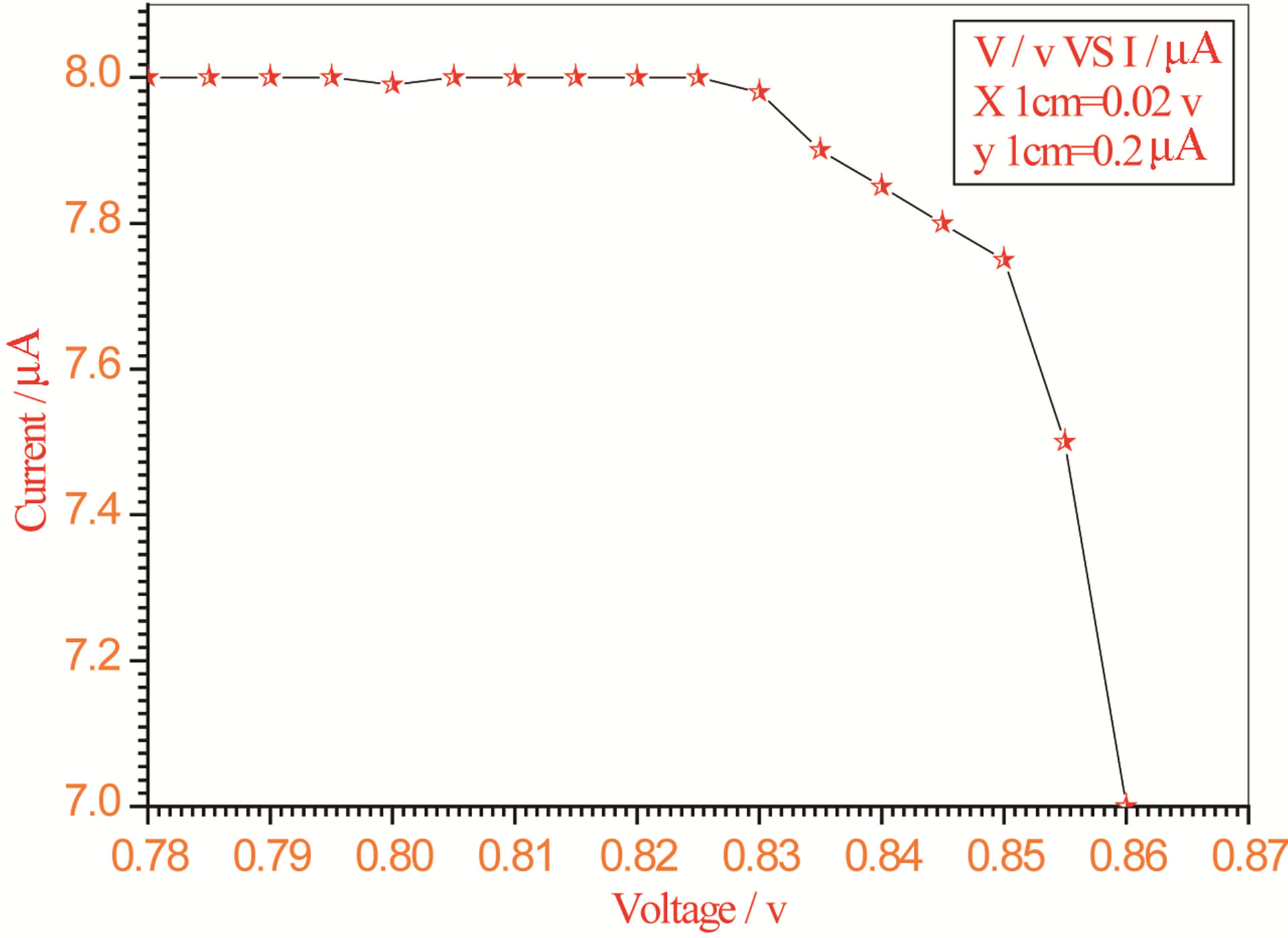
Figure 10. Relation between voltage and current for (Muscovite/TiO2/Dye/Al) (0.2 g concentration-800 rpm-300 K).
V-I relations for ordinary solar cells.
On one hand, V-I relation in Tables 1-3 show that when the concentration of 0.2 g and temperature of 300 K the efficiency increases with the rotation per Minuit, and it gives the maximum value of the efficiency. On the other hand, Tables 4-6 show that at the same concentration of 0.2 g, but, at temperature of 303 K, the efficiency still increases with the rotation per Minuit. But, it gives low value than that found with the lowest temperature, as shown in Tables 1-3. Tables 2 and 3 show that for the concentration 0.2 the cells can become more efficient than ordinary solar cells, as far as the efficiency exceeds 30%. In view of Figures 2-10, it is clear that the current decreases as the voltage increases. Thus after a certain threshold voltage the current vanishes even thought the voltage increases. Hence the TiO2/Dye/Al contact can act as a semi conductor diode. The fact that the TiO2 is connected with the positive source terminal of with respect to the Al contact indicates that the organic dye act as p type semi conductor.
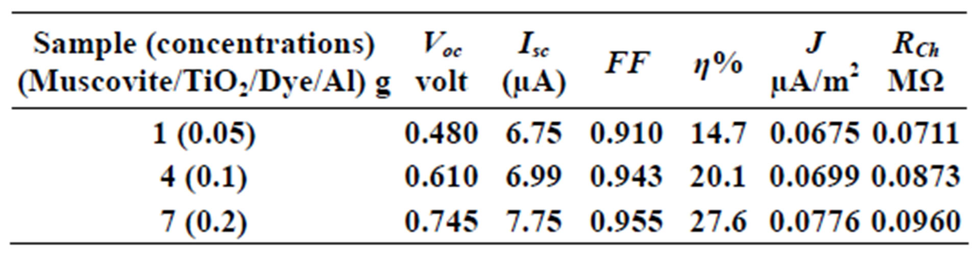
Table 1. Current-Voltage results fewer than 300 K-600 rpm.
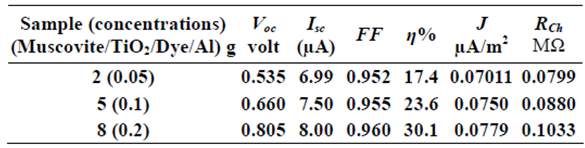
Table 2. Current-Voltage results fewer than 300 K-700 rpm.
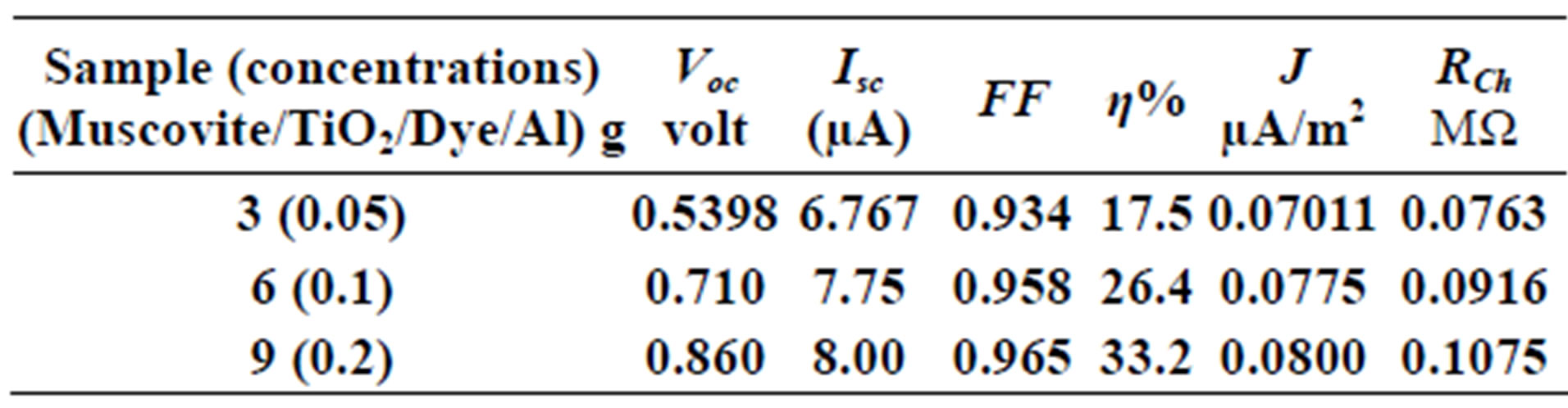
Table 3. Current-Voltage results fewer than 300 K-800 rpm.
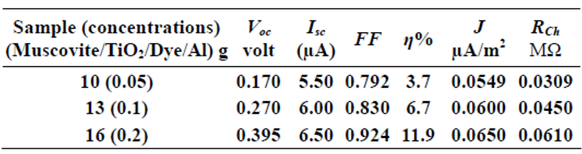
Table 4. Current-Voltage results fewer than 303 K-600 rpm.
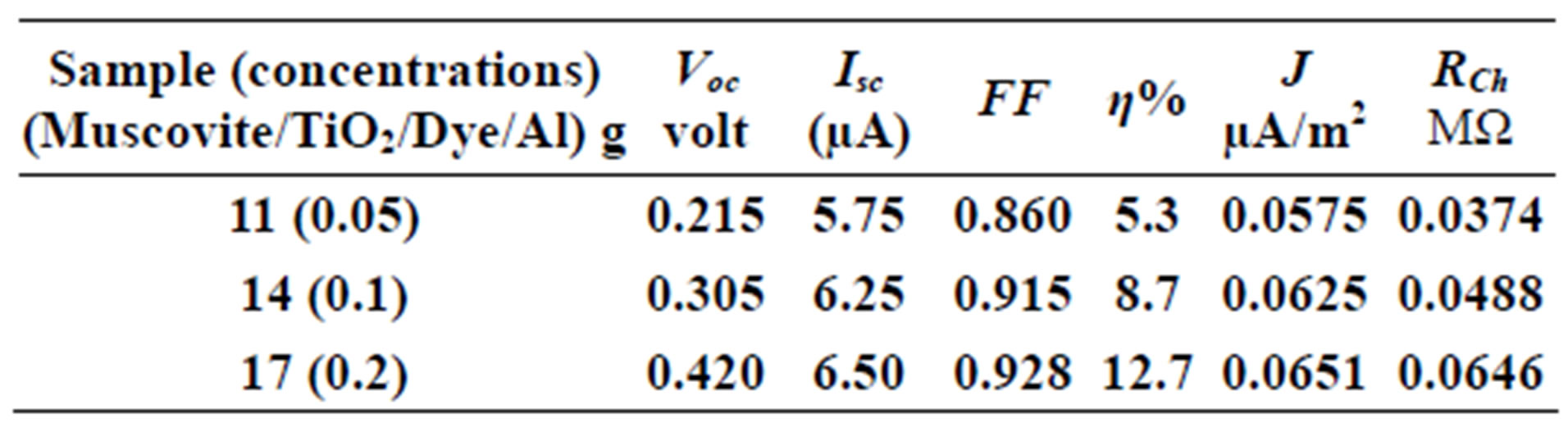
Table 5. Current-Voltage results fewer than 303 K-700 rpm.
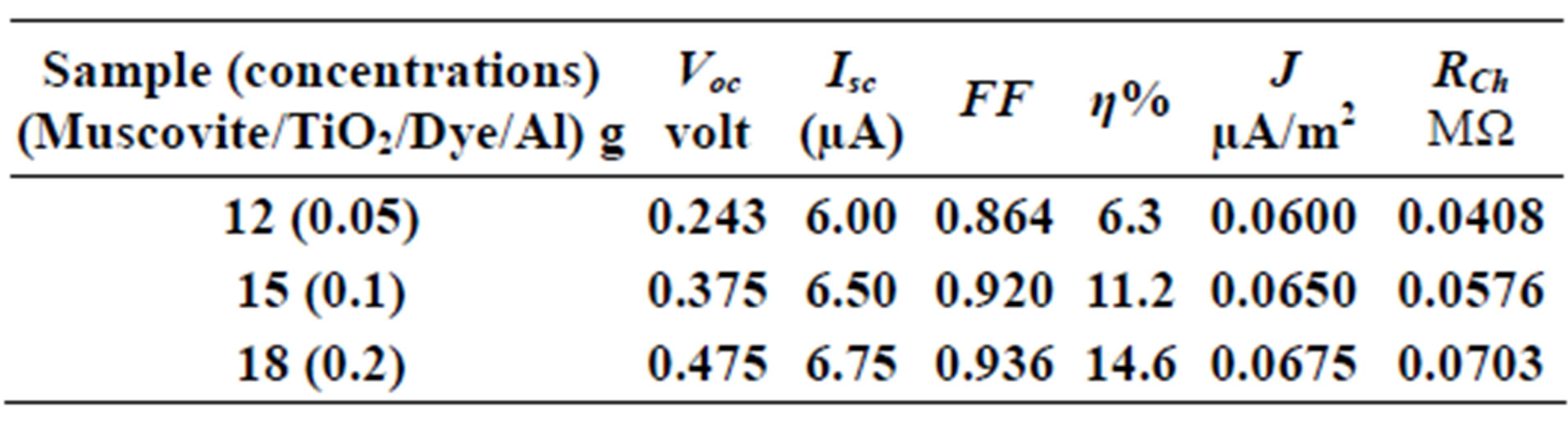
Table 6. Current-Voltage results fewer than 303 K-800 rpm.
8. CONCLUSION
The characteristics of the dye cells indicate that they are semiconductor materials. The fact that some dye cells samples are more efficient than solar cells indicates that such cells in the future can replace silicon solar cells. This is not surprising as for as dye cells are cheap and can be easily fabricated.
REFERENCES
- Park, J.H., Leeb, T.-W. and Kang, M.G. (2008) Growth, detachment and transfer of highly-ordered TiO2 nano tube arrays: Use in dye-sensitized solar cells. Chemical Communications, 25, 2867-2869. doi:10.1039/b800660a
- Liu, B. and Aydil, E.S. (2011) Layered mesoporous nanostructures for enhanced light harvesting in dye-sensitized solar cells. Journal of Renewable and Sustainable Energy, 3, 043106.
- Sukhatme, S.P. (2008) Solar energy principles of thermal collection and storage. 3rd Edition, Tata McGraw-Hill, Noida, 341.
- Gary, H.P. and Jprakash (2000) Solar energy fundamentals and applications. Tata Mc Graw-Hill, Noida, 434.
- Maycock, P.D. and Stirewalt, E.N. (1981) Photo voltaic sunlight to electricity in one step. 3rd Edition, Brick House, Andover, 222.
- Wolf, M. (1976) Historical development of solar cells in solar cells. IEEE Press, New York, 274.
- Singh, J. (1994) Semiconductor devices: An inter-duction. Mc Graw Hill, New York, 669.
- Mckelvey, J.P. (1966) Solid state and semiconductors physics. Krieger Publishing Company, New York, 512.
- Shockley, W. and Queisser, H.J. (1961) Detailed balance limit of efficiency of PN junction solar cells. Journal of Applied Physics, 32, 510-519.
- Green, M.A. (1981) Solar cell fill factors: General graph and empirical expressions. Solid State Electronics, 24, 788-789. doi:10.1016/0038-1101(81)90062-9