Engineering
Vol.4 No.11(2012), Article ID:24579,4 pages DOI:10.4236/eng.2012.411099
Numerical Study of Flow and Thermal Field on a Parallel Flow Vortex Tube
Department of Mechanical Engineering, Sepuluh Nopember Institute of Technology, Surabaya, Indonesia
Email: zulnoor@me.its.ac.id
Received September 3, 2012; revised October 5, 2012; accepted October 15, 2012
Keywords: Parallel Flow Vortex Tube; Energy Separation; Expansion; Compression; Secondary Flow; COP
ABSTRACT
Flow and thermal field of a parallel flow vortex tube has been simulated and analyzed numerically. A secondary zone model is found at the core region near the inlet to the middle of the vortex tube. Blockage effect due to a narrow area of the hot exit has deflected air flow towards the cold exit, caused expansion and compression at the cold and hot outlet, respectively. The cooling and heating effect due to energy separation is contributed by expansion and compression of air near the outlet. Coeficient of performance (COP) for a refrigerator is higher as cold mass fraction increases due to a higher temperature difference and cold mass flow rate.
1. Introduction
Vortex or swirl flows inside a circular tube can produce an energy separation of a single stream of air into two streams at higher and lower temperatures than the single one. This phenomena was firstly reported by Ranque [1] and then confirmed through detail examination by Hilsch [2] and well known as Ranque-Hirsch effect. The Ranque-Hilsch Vortex Tube (RHVT) is a simple and compact device with no moving parts and therefore it does not need any specific maintenance. RHVT is used in several industrial applications like cooling electronic controls and heat seals, separating gas mixtures, liqefying gases, purifying and dehydrating two-phase mixtures, separating particle in gas streams, etc.
Due to its simplicity and easiness in operation and maintenance there are many studies and investigations regarding RHVT have been done by people [3-8]. Ahlborn and Groves performed an experimental work [3] and proposed the existence of the secondary circulation flow imbedded into the primary vortex which moves fluid from the back flow core to the outher regions. Nimbalkar and Muller [4] carried out an experimental investigation to study the optimum cold end orifice for different inlet pressure and cold fractions. Their results showed that the maximum value of energy separation was reached at 60% cold fraction. Xue and Arjomandi [5] investigated the effect of vortex angle on the efficiency of the Ranque-Hilsch vortex tube. They found out through their experiment that the temperature difference (energy separation) was increased by giving a small vortex angle in the inlet zone of the vortex tube.
Apart from the experimental works there many other numerical studies regarding RHVT. T. Farouk and B. Farouk [6] performed large eddy simulations of the flow field and temperature separation in the Ranque-Hilsch vortex tube. Simulations were conducted for different cold mass fractions by changing the hot end pressure. The hot exit temperature separation was observed to increase with an increase in the cold mass fraction. The maximum hot exit temperature separation was found for a cold mass fraction of 0.78. Wills and Karthika [7] made numerical analysis of flow behaviour and energy separation in vortex tube using Fluent 6.3. There were a hot peripheral flow and a reversing cold inner core flow exists and a significant drop in total temperature due to the energy transfer to peripheral particles. The swirl velocity profiles in the radial direction indicated that the flow was dominated by the forced vortex regime. More recently, Pourmahmoud et al. [8] studied the effect of helical nozzles on the energy separation in a vortex tube. The results showed that this type of nozzles causes to form higher swirl velocity in the vortex chamber than the straight one which can effectively increase amount of energy separation and cold gas temperature difference.
There are two types of vortex tube flow i.e. counter flow and parallel flow. According to our knowledge there is lack information regarding parallel flow vortex tube. All the references mentioned above refer to the counter flow vortex tube. Furthermore, we perform a numerical analysis of fluid flow and thermal field on a parallel vortex tube. The temperature, pressure and velocity distribution will be observed in order to study the flow behaviour and energy separation in the parallel vortex tube.
2. Numerical Modeling
The parellel flow vortex tube was modeled using Fluent 6.3. The relative geometrical parameter (Figure 1) were considered having a 10 mm diameter vortex tube with L/D = 10, Ai/A = 0.1147, Aho/A = 0.0975, and Aco/A = 0.09, where L, A, i, ho and co were the tube length, area, vortex tube inlet, hot gas outlet and cold gas outlet, respectively.
The hexahedral and quadrilateral cells were used in order to maintain the number of cells as low as possible. To avoid an unaccurate analysis due to the grid coarseness, we carried out the simulations using different number of cells as shown in Table 1. Since there is no significant different in results after the number of cells

Figure 1. Simple parallel flow vortex tube with four tangential inlet nozzles.
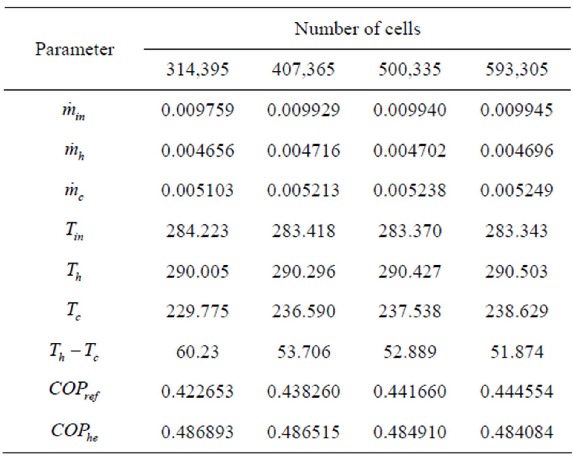
Table 1. Grid size independence study.
was increased up to 500,335, this number of cells then was used for the entire simulations.
The selected solver for the simulation was a pressure base implicit, 3D and steady state. The flow inside a vortex flow was definitely compressible and turbulent. Air as gas ideal was selected and standard k-ε model with standard wall functions was chosen for the turbulence model in the simulation. SIMPLE was applied to solve velocity-pressure couple and second-order upwind scheme was used to discritize the continuity, momentum and energy equations.
We applied the following boundary conditions for the present simulation:
• Pressure inlet boundary condition to the inlet region of the vortex tube (at inlet of nozzle) with total pressure of 5 bar (gauge) and total temperature of 300 K.
• Pressure outlet boundary condition to cold end and hot end region of the vortex tube. Pressure was varied in order to adjust the fraction of outlet cold and hot gas flows.
• No slip with zero heat flux (adiabatic) condition was used for all the walls.
• The operating condition was 1 bar (absolute) and 300 K.
3. Results and Discussion
3.1. Flow Field
The free and forced vortex flow inside the parallel fow vortex tube are shown in Figure 2.
The free vortex at the peripheral and the forced vortex at the core flow towards the exit ports as hot and cold stream, respectively. Furthermore, we pick the case of cold mass fraction 0.53 in order to discuss more detail regarding the flow and thermal fields inside the parallel flow vortex tube by exploring velocity, pressure and temperature distributions.
Air enter the vortex tube through four rectangular inlet nozzles tangentially. The free vortex flow at the peripheral has a higher tangential velocity than the forced vortex flow at the core as shown in Figure 3(a). This velocity decreases when travelling toward the outlet ports. On

Figure 2. Free and forced vortex flow.
 (a)
(a)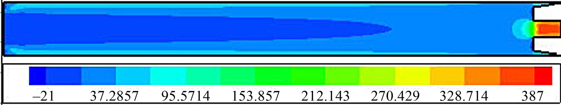 (b)
(b)
Figure 3. Velocity distribution, m/s: (a) Tangential velocity, m/s; (b) Axial velocity.
the other hand, the axial velocity is found higher at the core than the peripheral as shown in Figure 3(b). The negative values of axial velocity at the core indicates the presence of backflow which is supported by plot of streamlines in Figure 4. This backflow reveals existance of the secondary circulation model which was proposed by Ahlborn and Groves [3] in their work regarding counter flow vortex tube. The axial velocity at the core increases after the recirculation zone and it decreases at the peripheral in the flow direction.
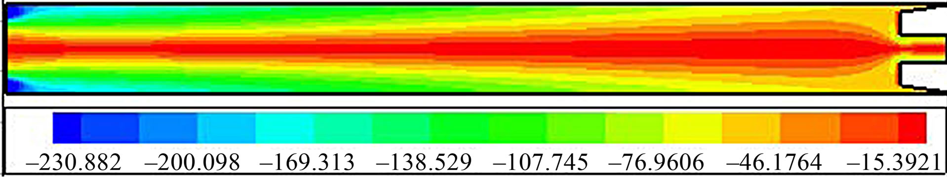
Velocity has relation with the static pressure as shown in Figure 5. Pressure reduces radialy inwards throughout the length of vortex tube. There are two regions in the axial direction. Pressure reduces towards hot outlet in the peripheral region. In the core region pressure increases towards cold outlet and decreases after reaching the middle length of vortex tube. The expansion near the cold outlet port causes pressure drop as well as temperature (Figure 6). The lower pressure and velocity at the core indicates the lower energy than the peripheral area.
3.2. Thermal Field
The energy separation mechanism in the parallel flow vortex tube is observed to be different with that of counter flow vortex tube. As for a counter flow vortex flow, temperature gradually drops along core region when air flows towards cold exit. In the present parallel flow vortex tube, temperature of the core and peripheral region increase until near exit. The blockage effect due to a narrow area of hot exit causes air flows towards cold exit mostly. As a result an adiabatic compression and expansion takes place in hot and cold exit, respectively. The expansion leads to pressure drop (Figure 5), followed by temperature (Figure 6), and then creates a cold air stream at the cold exit.
A vortex tube can be considered as a refrigerator therefore, there are some parameters should be measured in order to determine its performance. Energy separation rate can be used to analyze cooling capacity of a vortex tube. The rates of energy separation or cooling rate is determined as follows:

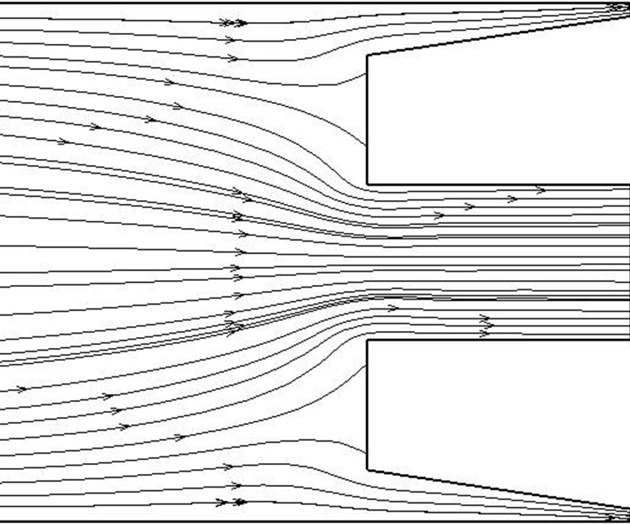
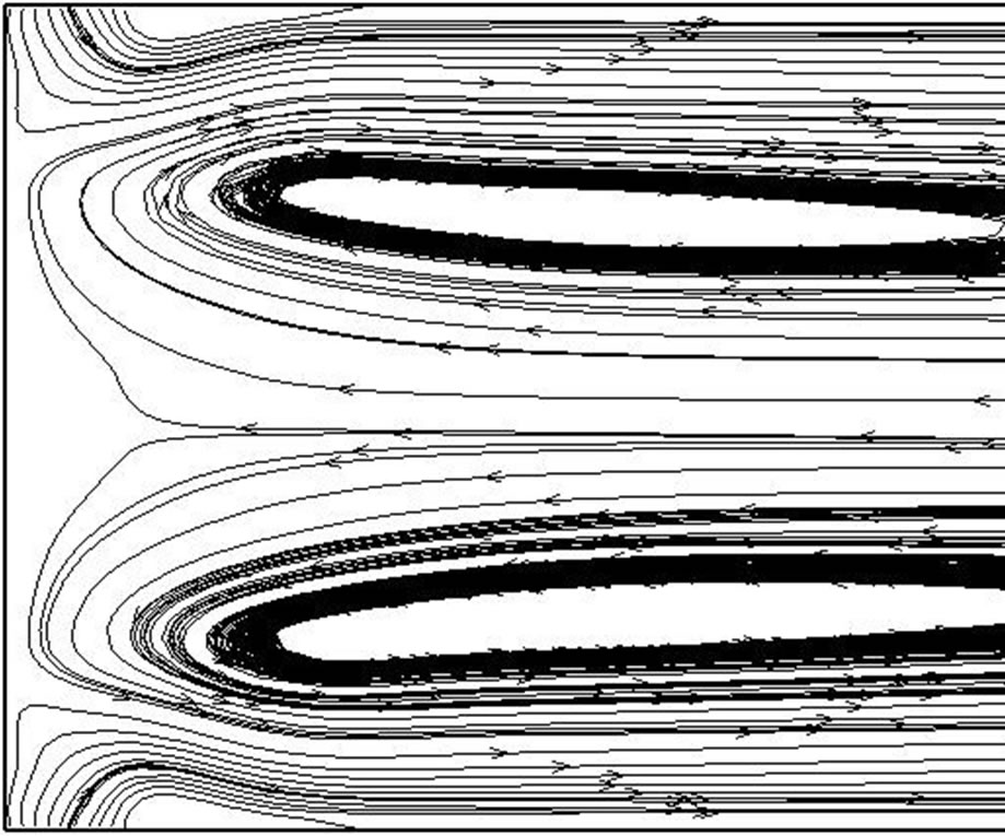
Figure 4. Plot of streamlines near inlet and outlet port.
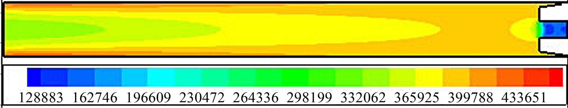
Figure 5. Pressure distribution, Pa.
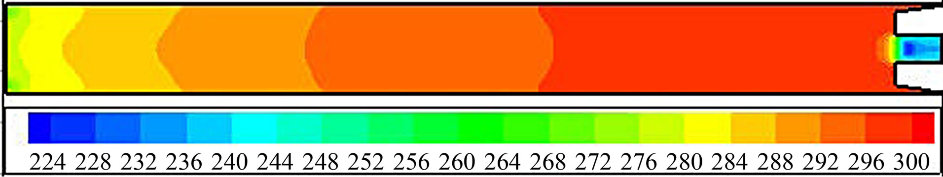
Figure 6. Temperature distribution, K.
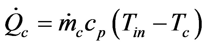 (1)
(1)
Then its performance characteristic is evaluated using the coefficient of performance (COP) which is calculated by deviding the energy separation rate on the work to compress the air from atmospheric pressure and temperature to the inlet condition.
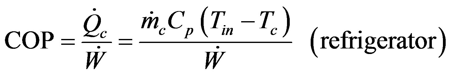 (2)
(2)
The compression work is calculated for a gas ideal with a polytropic process,
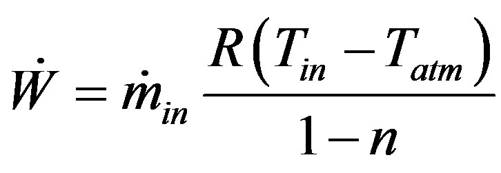 (3)
(3)
with
 (4)
(4)
where  and P are energy separation rate, compression work, mass flow rate, gas constant, specific heat, temperature and pressure respectively, while the subscript in, h, c and atm refers to inlet, hot, cold and atmospheric conditions, respectively.
Plot of COP and temperature difference between inlet and cold exit as a function of cold mass fraction is given in Figure 7. It can be observed that COP for a cooling system (refrigerator) has raised at a higher cold mass fraction. COP is improved when cooling or heating effect
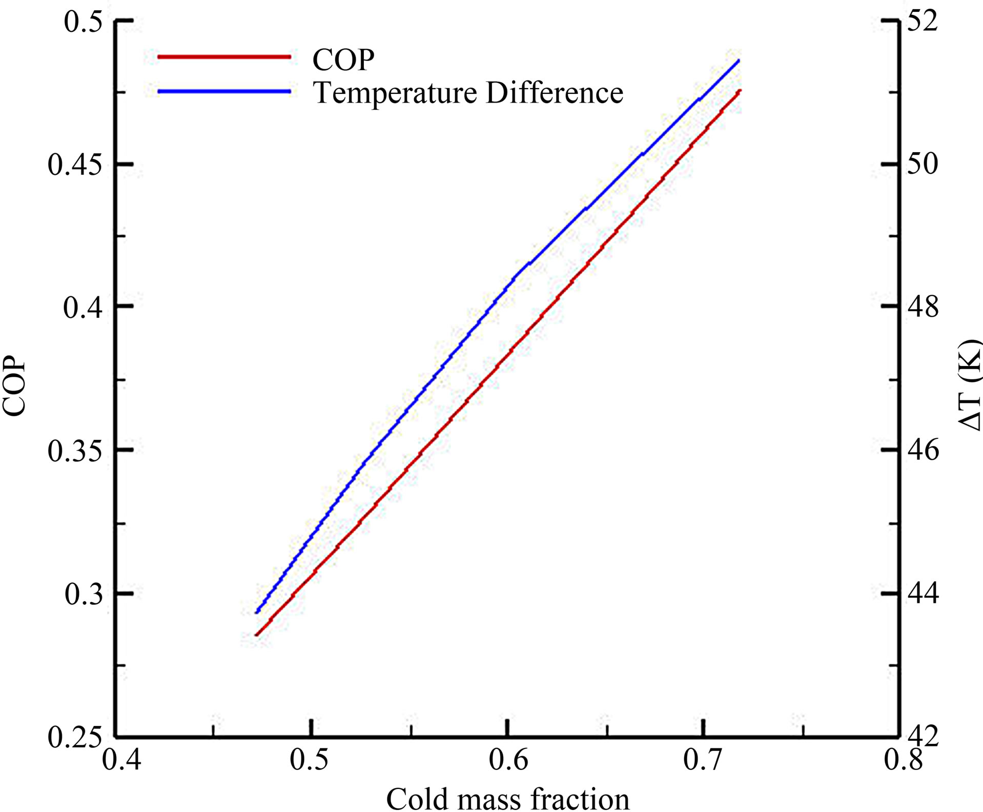
Figure 7. Coeficient of performance (COP) and temperature difference of the parallel flow vortex tube.
is increased through a higher temperature difference and mass flow rate. However, the coefficent of peformance of a vortex tube is still lower than that of conventional refrigeration systems.
4. Conclusion
Flow and thermal field of a parallel flow vortex tube has been simulated and analyzed numerically. Swirl velocity is observed higher at the peripheral region than the core one. On the contrary, axial velocity at the core is higher than the peripheral. This axial velocity has negative value near the inlet region to the middle of the vortex tube, indicated the presence of backflow or secondary zone as found at a counter flow vortex tube. The cooling and heating effect due to energy separation is contributed by expansion and compression of air near the outlet. Blockage effect at the hot exit deflects air stream to the cold exit. Expansion of air leads pressure and temperature drop at cold exit. Coefficient of performance (COP) for refrigerator is higher as cold mass fraction increases.
5. Acknowledgements
We thank to the university for the support to fund this work under Grant No. 1027.171/IT2.7/PN01/2012.
REFERENCES
- G. J. Ranque, “Experiments on Expansion in a Vortex with Simultaneous Exhaust of Hot and Cold Air,” Le Journal De Physique et le Radium (Paris), Vol. 4, 1933, pp. 112-114.
- R. Hilsch, “The Use of the Expansion of Aires in Centrifugal Field as a Cooling Process,” Review of Scientific Instrument, Vol. 18, No. 2, 1947, pp. 108-113. doi:10.1063/1.1740893
- B. Ahlborn and S. Groves, “Secondary Flow in a Vortex Tube,” Fluid Dynamics Research, Vol. 21, No. 2, 1997, pp. 73-86. doi:10.1016/S0169-5983(97)00003-8
- S. U. Nimbalkar and M. R. Muller, “An Experimental Investigation of the Optimum Geometry for the Cold End Orifice of a Vortex Tube,” Applied Thermal Engineering, Vol. 29, 2009, pp. 509-514. doi:10.1016/j.applthermaleng.2008.03.032
- Y. Xue and M. Arjomandi, “The Effect of Vortex Angle on the Efficiency of the Ranque-Hilsch Vortex Tube,” Experimental Thermal and Fluid Science, Vol. 33, No. 1, 2008, pp. 54-57. doi:10.1016/j.expthermflusci.2008.07.001
- T. Farouk and B. Farouk, “Large Eddy Simulations of the Flow Field and Temperature Separation in the RanqueHilsch Vortex Tube,” International Journal of Heat and Mass Transfer, Vol. 50, 2007, pp. 4724-4735. doi:10.1016/j.ijheatmasstransfer.2007.03.048
- N. J. Wills and A. S. Karthika, “Numerical Analysis of Flow Behaviour and Energy Separation in Vortex Tube,” 10th National Conference on Technological Trends (NCTT 09), 6-7 November 2009, pp. 130-135.
- N. Pourmahmoud, A. H. Zadeh, O. Moutaby and A. Bramo, “Computational Fluid Dynamic Analysis of Helical Nozzles Effects on the Energy Separation in a Vortex Tube,” Thermal Science, Vol. 16, No. 1, 2012, pp. 151-166. doi:10.2298/TSCI110531085P