Engineering
Vol. 4 No. 7 (2012) , Article ID: 20538 , 4 pages DOI:10.4236/eng.2012.47052
A New Closure to Slice Model for Slope Stability Analysis
1State Key Laboratory of Hydro-Science and Engineering, Tsinghua University, Beijing, China
2Computational Geosciences Research Centre, Central South University, Changsha, China
Email: liuty@tsinghua.edu.cn
Received April 23, 2012; revised May 16, 2012; accepted May 28, 2012
Keywords: Slope Stability; Slice Model; Limit Equilibrium; Safety Factor; Minimal Inter-Slice Action
ABSTRACT
This paper presents a new closure to slice models for evaluating slopes. The discussion is based on the minimal interslice action (MIA) hypothesis, which results in a new slice model without including artificially adjustable parameters. It has been realized that the new slice model predicts the minimum value of the safety factor, while all other slice models available always overestimate the value of the safety factor. Moreover, the gravity moment of each slice is found to be opposite to the overturning moment, which is different from the existing knowledge. In particular, the new slice model overcomes the situation where different assumptions of the inter-slice force function will give different safety factors to the same slope. The related numerical examples indicate that the new slice model can serve as a reliable tool for investigating geotechnical slope stability.
1. Introduction
An accurate model for evaluating slope stability can provide considerable help for mitigating slope geological hazards [1]. However, existing models based on the methods of slices are statically indeterminate under the limit equilibrium state [2,3]. For a deformable body, we have a constitutive relationship between stresses and strains [4]. But as for the slice with its slight deformation ignored, we have to seek an implicit relationship between the unknowns [5,6]. Commonly used approaches assume the thrust line of the slope, as well as the location of the normal force on the slice base, resulting in a closure of the equilibrium equations [7]. However, the selection of the inter-slice force function depends heavily on intuition and experience [3,5,8-12]. Moreover, these assumptions are inconsistent with the experimental observations due to the fact that the normal and shear stresses are both non-uniform on the interface of blocks in contact [13]. Up to now, the closure to the slice model, despite over 60 years of study, remains an open question. For example, Ref. [1] clearly stated that: “Extensive engineering and research studies performed over the past 70 years provide a sound set of soil mechanics principles with which to attack practical problems of slope stability. Despite the advances that have been made, evaluating the stability of slopes remains a challenge.”
In this paper, we propose the minimal inter-slice action (MIA) hypothesis, which embodies an optimal closure to the slice model. With this new closure, the slice model has no artificially adjustable parameters for the selection of inter-slice force functions. In addition, the gravity moment of each slice is found to be in the opposite direction to the overturning moment. The numerical results show that the new slice model predicts the minimum value of the safety factor, while all other existing slice models commonly overestimate the stability of slopes.
2. Existing Slice Models
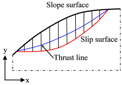
When investigating the stability of slopes in soil or rock, the slice model is always employed [1,14,15]. In this method, the sliding mass above the potential slip surface is divided into a number of vertical slices, as shown in Figure 1(a).
The actual number of slices used dependents on the slope geometry and soil or rock profile. For a curved slip surface, the slice base can be assumed as a straight line, with a negligible loss in accuracy. Adjoining slices interact and transfer inter-slice forces. The role of the interslice force is twofold: 1) to support the slices on its right side, and 2) to thrust the ones on its left side. In contrast, the forces on the slice base always prevent the slice from sliding. A typical slice is shown in Figure 1(b).
Here only the known gravity and surface forces are considered. Additional known forces such as seismic forces, reinforcement forces, and pore water pressures can however be easily included. When the slice is just about to slide, the following force equilibrium equations can be obtained by summing forces in each direction perpendicular or parallel to the slice base (discuss moment equilibrium will be considered later):
 (1)
(1)
 (2)
(2)
where R and S are the normal and shear forces on the slice base; T and β are the unknown magnitude and inclination angle of the inter-slice force; T0 and β0 are the known magnitude and inclination angle of the surface force on the slice; G is the gravity force of the slice, and α is the inclination angle of the slice base.
In addition to these equilibrium considerations, according to the Mohr-Columb failure theory [16], the critical shear force on the slice base can be represented by the reduced shear strength:
S = (c + μR)/fs (3)
where c is the cohesion coefficient and μ is the friction coefficient (for the drained shear strength, the effective values of  and
and  replace the parameters c and μ in Equation (3)), fs is the safety factor, by which the shear strength must be reduced to bring the slice into a state of limiting equilibrium.
Equations (1) to (3) contain four unknowns (R, S, T, and β), indicating that the number of unknowns is greater than that of equations. To make a balance between the number of equations and the number of unknowns, most researchers assume that the thrust line of the slope, or the inclination of the inter-slice force, is in the form of tan β = λf(x), where λ is a scaling factor [3,5,7-9,11,12]. The commonly used inter-slice force functions include f(x) = 1, the half-sine, trapezoidal and error functions [17]. However, different assumptions have produced different values of the safety factor [1-2,6].
3. Minimum Inter-Slice Force
In this study, we propose a new hypothesis that provides an optimal condition for the slice model. For this purpose, it is assumed that interaction between the slices is reduced to a minimum under the limit equilibrium state. The newly-proposed hypothesis states that, among all the admissible inclination angles of the inter-slice force, there is one and only one inclination angle that minimizes the magnitude of the inter-slice force, so that it can be used to determine the normal force on the slice base. Based on the newly-proposed hypothesis, we substitute Equations (1) and (3) into Equation (2) and obtain the following equation:
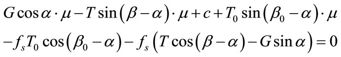 (4)
(4)
Upon rearranging, we obtain the following more concise equation:
 (a)
(a)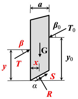 (b)
(b)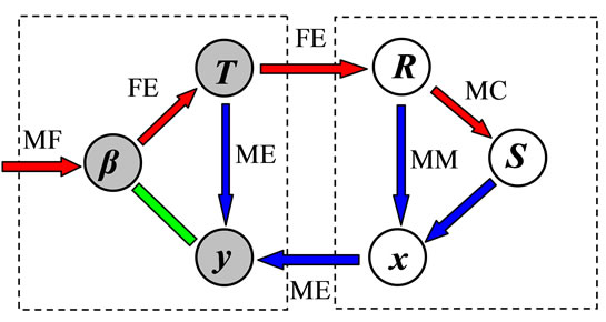 (c)
(c)
Figure 1. (a) Slope with noncircular slip surface and interaction slice model; (b) Typical vertical slice with both known and unknown variables (the unknowns are shown in red color); (c) Interaction between the unknowns of each slice.
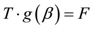 (5)
(5)
where functions g(β) and F can be expressed as
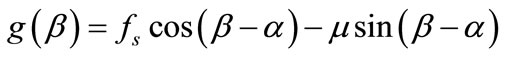 (6)
(6)
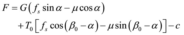 (7)
(7)
With a trial value of the safety factor, if function F remains constant, then inter-slice force T will be inversely proportional to function g(β) in Equation (5). In fact, the slice automatically selects inclination angle β to minimize interslice force T, and results in an efficient way to prevent the slice from sliding. Function g(β) reaches the maximum of when β satisfies the following relationship:
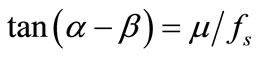 (8)
(8)
At the same time, inter-slice force T arrives at a minimum:
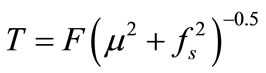 (9)
(9)
At first glance through Equation (8), the inclination angle of the inter-slice force seems to be only locally related to the physical parameters of each slice. In fact, as the safety factor is defined globally, the inclination angle of the inter-slice force is also affected by other slices. With fs known in Equation (8), the newly proposed hypothesis indeed provides a closure for the slice model. Furthermore, the new closure contains no artificially adjustable parameters, which is different from the commonly assumed force functions [1,3,17]. With this closure used, it is straightforward to solve the equilibrium equations of the slice model.
4. Minimum Moments
After the force equilibrium is considered, we now turn to consideration of the moment equilibrium of the slice shown in Figure 1(b). Summing the moments for the left corner of the slice base gives the following moment equilibrium equation:
 (10)
(10)
where x and y are the location coordinates of the normal force on the slice base and inter-slice force, respectively, a is the width of the slice, and 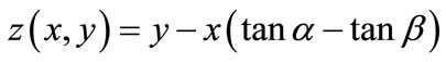 and
and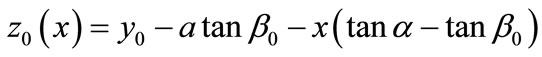 are two equivalent moment arms, respectively. On the right-hand side of Equation (10), although the gravity moment (the second term) can be included in the overturning moment (the first term), we keep it separate to show its exceptional effect (see below).
Once again, the number of equilibrium equations is less than the unknowns (x and y). To obtain a statically determinate solution, the value of unknown x has been assumed explicitly or implicitly, such as the midpoint of the base of the slice [1,5,8]. With this assumption, Equation (10) can be solved explicitly for the location of the inter-slice force. In addition, this assumption is equivalent to the uniform distribution of the normal stress on the slice base. However, past laboratory experiments have shown that both the distributions of normal and shear stresses are non-uniform over the slice base [13]. In particular, the strong nonuniformity of normal force exists near the block edges to compensate for the overturning moment.
Based on the newly-proposed hypothesis, we expect that among all the admissible locations of the normal force on the slice base, there is one and only one location that minimizes both the external and inter-slice moments, so that the location of the inter-slice force can be uniquely determined. Through examining the external moments on the right-hand side of Equation (10), we find out that the gravity moment increases with an increase in unknown x, and that the overturning moment decreases with an increase in unknown x. In the case of the overturning moment being zero, the gravity moment will reach zero at x = 0.5a, which is coincident with the common assumption mentioned above. For a positive overturning moment, letting x < 0.5a would minimize the external moments, resulting in a negative gravity moment. On the other hand, letting x > 0.5a would minimize the external moments to a negative overturning momentresulting in a positive gravity moment. Therefore, the gravity moment is always in the opposite direction to the overturning moment, which is different from our existing knowledge [1]. In addition, the gravity moment can reach a value as high as 0.5 Ga. If the overturning moment is less than this value, the gravity moment can sufficiently balance it, with no inter-slice moment induced. Otherwise, the overturning moment will induce an inter-slice moment. Figure 1(c) represents schematically a whole interaction relationship among the unknowns of any slice.
The left dashed block consists of three elements of the inter-slice force, while the right is the supporting force on the slice base. FE denotes the force equilibrium conditions, MC the Mohr-Columb criteria, ME the moment equilibrium conditions, MF the minimum force condition, and MM the minimum moment condition. Following the red arrows the unknown forces can be determined, while following the blue ones the unknown locations of the normal force on the slice base and the inter-slice force can be determined.
5. Numerical Examples
We employed the trial-and-error procedure to solve Equations (1) to (10) [1]. With the value of a given safety factor, the trial-and-error procedure starts from the uppermost slice and then deals recursively with one slice at a time until the last slice is reached. This process is repeated with the fs values adjusted, until the locations of all inter-slice forces always lie within the sliding mass and no inter-slice force acting on the left boundary of the last slice. Once the convergence conditions are satisfied, the magnitude, inclination angle and location of each inter-slice force are simultaneously obtained. So do the forces on each slice base.
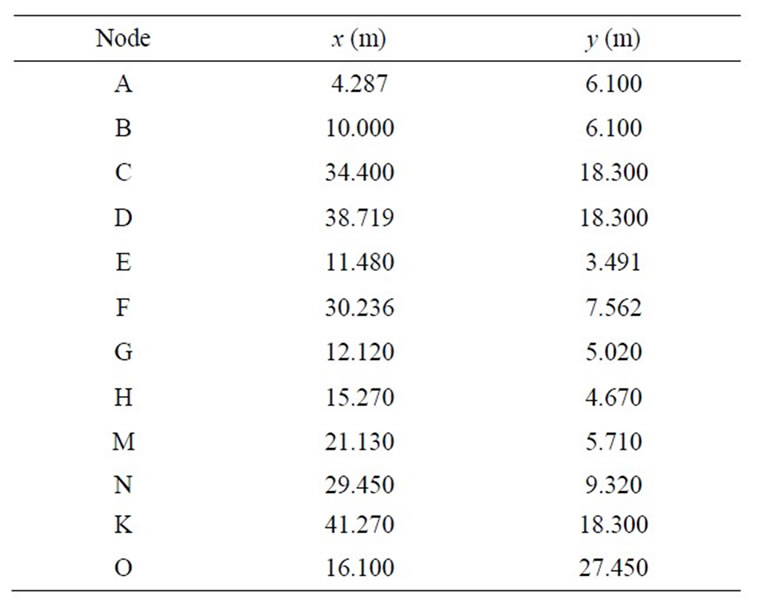
We consider three typical slope models (Model 1, Model 2, and Model 3) shown in Figure 2, with the same slope of 1:2 and the same material parameters: c = 20 kN,  and
and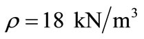 . The coordinates of key points A to K of each model are listed in Table 1. Figure 3 shows the typical thrust lines found by the new slice model.
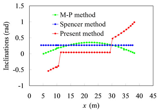
Also shown in Figure 3 are the results obtained by three existing slice models. Hereafter, the M-P method, which denotes the Morgenstern-Prince method, employs a half-sine shape of the inter-slice force function, while the Spencer method uses a constant as the inter-slice force function. As shown in Figure 3(a), the new slice method produces both the positive and negative inclination angles of the thrust, but in contrast, both the M-P and Spencer methods only provide the positive inclination angles. The distributions of the thrust magnitudes are similar in shape for all the three slice methods, as shown
 (a)
(a)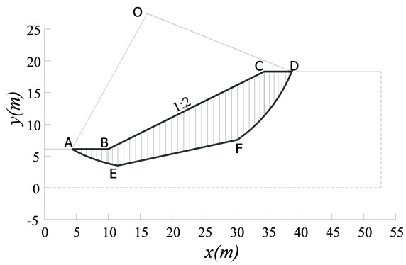 (b)
(b)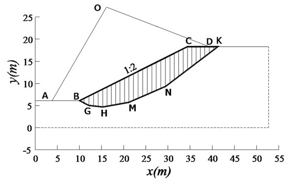 (c)
(c)
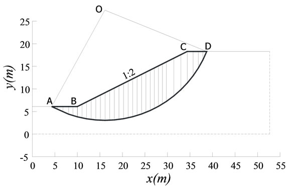
Figure 2. Three typical slope models. (a) Model 1 with a circle slip surface at the point O is divided into 32 vertical slices; (b) Model 2 with a curvilinear slip surface is divided into 41 slices; (c) Model 3 with a polygonal slip surface is divided into 31 slices.
 (a)
(a)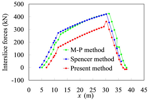 (b)
(b)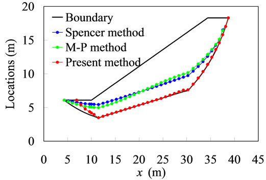 (c)
(c)
Figure 3. (a) Inclination angle distributions of the curvilinear slope shown in Figure 2(b); (b) Distributions of the thrust magnitudes of the curvilinear slope shown in Figure 2(b); (c) Distributions of the thrust locations of the curvilinear slope shown in Figure 2(b).
in Figure 3(b). Compared with the values of thrust predicted by the M-P and Spencer methods, those predicted by the present method are smaller throughout the whole sliding mass.
Since the locations of thrust predicted by the present method are different from those obtained by both the M-P and Spencer methods, the present method does not produce inter-slice moment within the sliding mass, except in the anticline region, as shown in Figure 3(c).
Within the anticline slices, the location of the interslice forces moves upward until the top boundary of slope is reached, which qualitatively agree with the experimental observations [13]. This result shows that the inter-slice moment has been produced when the normal and shear forces on the inter-slice boundary are no longer non-uniformly distributed. In addition, the upward location of the thrust can counter the overturning moment.
Table 2 lists the values of the safety factor for three
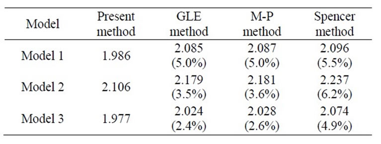
Table 2. Comparison of the calculated values of the slope safety factors.
typical slope models predicted by the new slice method and three existing methods.
The percentage shown in the parentheses indicates the overestimating ratio of the safety factor obtained by three existing slice models to that of the present slice model. Although both the GLE method, which denotes the generalized limit equilibrium method with a half-sine shape of the inter-slice force function, and the M-P method produce nearly identical results, the Spencer method yields lager safety factor values. For each case, the present model results in the minimum value of the safety factor. For the three slopes investigated, all the three existing methods employed overestimate the stability slopes as much as 6.2%.
The reason for the three existing slice models to overestimate the safety factor is that the statically indeterminate slice or slope has an infinite number of possible inclination angles and locations for the inter-slice force. The three existing slice models provide less flexibility in the assumptions for the inter-slice force, which leads to the slopes being reinforced. Thus, it is very difficult, if not impossible, for the existing slice models to seek the real inclination angle and location of the thrust line with the minimum value of safety factor.
6. Conclusion
The newly-proposed hypothesis can provide a complete closure for the slice model. The new slice model naturally satisfies all the conditions of static equilibrium, producing the minimum value of the safety factor, while the existing slice models commonly overestimate the stability of slopes. The new slice model mainly concerns the global limit equilibrium of slopes, although its slight deformation is ignored. In future we aim to extend the 2D slice model to a 3D block model. The accurate model prediction, in combination with systematic observation and testing, would significantly increase the confidence in evaluating slope stability.
7. Acknowledgements
This work was supported by the State Key Laboratory of Hydro-Science and Engineering (2009-TC-2, 2008Z6). The first author also acknowledges the support of the Scientific Foundation for Returned Oversea Scholars of China (20101020044).
REFERENCES
- J. M. Ducan and S. G. Wright, “Soil Strength and Slope Stability,” Chapter 6, John Wiley & Sons, Inc., New York, 2005.
- L. W. Abramson, T. S. Lee, S. Sharma and G. M. Boyce, “Slope Stability and Stabilization Methods,” 2nd Edition, Wiley, New York, 2002.
- Y. M. Cheng, Z. H. Zhao and Y. J. Sun, “Evaluation of Interslice Force Function and Discussion on Convergence in Slope Stability Analysis by the Lower Bound Method,” Journal of Geotechnical and Geoenvironmental Engineering, Vol. 136, No. 8, 2010, pp. 1103- 1113. Hdoi:10.1061/(ASCE)GT.1943-5606.0000317
- S. Timoshenko and J. N. Goodier, “Theory of Elasticity,” McGraw-Hill Companies, Inc., New York, 1970.
- Z. Y. Chen and N. R. Morgenstern, “Extensions to the Generalized Method of Slices for Stability Analysis,” Canadian Geotechnical Journal, Vol. 20, No. 1, 1983, pp. 104-119. Hdoi:10.1139/t83-010
- J. Krahn, “The 2001 R. M. Hardy Lecture: The Limits of Limit Equilibrium Analyses,” Canadian Geotechnical Journal, Vol. 40, No. 3, 2003, pp. 643-660. Hdoi:10.1139/t03-024
- N. Janbu, “Slope Stability Computations,” EmbankmentDam Engineering: Casagrande Volume, John Wiley & Sons, Inc., New York, 1973, pp. 47-86.
- N. R. Morgenstern and V. E. Price, “The Analysis of the Stability of General Slip Surfaces,” Géotechnique, Vol. 15, No. 1, 1965, pp. 79-93. Hdoi:10.1680/geot.1965.15.1.79
- E. Spencer, “A Method of Analysis of the Stability of Embankments Assuming Parallel Inter-Slice Forces,” Géotechnique, Vol. 17, No. 1, 1967, pp. 11-26. Hdoi:10.1680/geot.1967.17.1.11
- S. K. Sarma, “Stability Analysis of Embankments and Slopes,” Géotechnique, Vol. 23, No. 4, 1973, pp. 423-433. Hdoi:10.1680/geot.1973.23.3.423
- D. Y. Zhu, C. F. Lee, Q. H. Qian and G. R. Chen, “A Concise Algorithm for Computing the Factor of Safety Using the Morgenstern-Price Method,” Canadian Geotechnical Journal, Vol. 42, No. 1, 2005, pp. 272-278. Hdoi:10.1139/t04-072
- S. Tinti and A. Manucci, “Gravitational Stability Computed through the Limit Equilibrium Method Revisited,” Geophysical Journal International, Vol. 164, No. 1, 2006, pp. 1-14. Hdoi:10.1111/j.1365-246X.2005.02796.x
- O. Ben-David, G. Cohen and J. Fineberg, “The Dynamics of the Onset of Frictional Slip,” Science, Vol. 330, No. 6001, 2010, pp. 211-214. Hdoi:10.1126/science.1194777
- K. E. Petterson, “The Early History of Circular Sliding Surfaces,” Géotechnique, Vol. 5, 1955, pp. 275-296. Hdoi:10.1680/geot.1955.5.4.275
- A. W. Bishop, “The Use of Slip Circles in the Stability Analysis of Earth Slopes,” Géotechnique, Vol. 5, No. 1, 1955, pp. 7-17. Hdoi:10.1680/geot.1955.5.1.7
- K. Fan, D. G. Fredlund and G. W. Wilson, “An Interslice Function for Limit Equilibrium Slope Stability Analysis,” Canadian Geotechnical Journal, Vol. 23, No. 3, 1986, pp. 287-296. Hdoi:10.1139/t86-042
- D. M. Wood, “Soil Behavior and Critical State Soil Mechanics,” Cambridge University Press, Cambridge, 1990.