Materials Sciences and Applications
Vol.3 No.5(2012), Article ID:19205,7 pages DOI:10.4236/msa.2012.35046
On the Validity of the Effective Index Method for Long Period Grating Photonic Crystal Fibers
![]()
1Ecole Polytechnique de Montreal, Genie Physique, Montreal, Canada; 2Laboratoire de Physique Quantique et Photonique, Faculte des Sciences de Tunis, Tunis, Tunisia, 3Faculté des Sciences de Bizerte, Bizerte, Tunisia; 4Department of Physics, Jazan University, Jazan, KSA.
Email: *belhadj.walid@fsb.rnu.tn
Received February 9th, 2012; revised March 5th, 2012; accepted April 11th, 2012
Keywords: Long Period gratings photonic crystal fiber (LPG-PCF); improved effective index; MMP; Cladding modes; sensor; sensitivity
ABSTRACT
This paper focuses on the investigation of modal characteristics and sensing properties of long period grating photonic crystal fibers (LPG-PCFs). An improved effective index method is employed with an objective to study its limitations for various designs of LPG-PCFs. Results so obtained with the above method are compared with the corresponding values of multiple multipole (MMP) method results which points the range of validity and applicability of the improved effective index method to LPG-PCFs. It is shown that this method is excellent when the surrounding media is assumed to be air. However, it becomes less accurate when the fiber is immersed into a liquid with a refractive index close to that of the cladding.
1. Introduction
The development of long-period grating (LPG) has had a significant impact on fiber optic sensing. It is known that the spectral response of LPG is sensitive to local environment such as temperature, strain, bend radius and refractive index of the medium surrounding the fiber. LPG sensor is distinct from other fiber optic sensing techniques such as fiber-laser-based sensing [1] as LPG can perform simultaneous multiple parameter measurement. Moreover, the sensitivity of LPG to the surrounding refractive index has been extensively studied to extend the application range, namely in biomedical and chemical sensing [2]. Applications of LPGs in temperature [3], strain [4], and bend [5,6] sensors have since been demonstrated. However, for chemical sensors, it is mainly the sensitivity of LPGs to the surrounding refractive index that is of interest for sensor development. Examples of chemical sensors for sugar [7], aromatic compounds [8], and hydrocarbons [9] based on the detection of refractive index change using LPGs have been presented in the literature. In these applications, direct sensing was used to detect changes in the refractive index of mixtures in a region close to the refractive index of the fiber cladding, which is the most sensitive interval. Indirect sensing of analytes is also possible using a chemically selective layer, again with a refractive index close to that of the cladding [10].
Because of the wide range of applications mentioned above, there is a growing interest in optical refractive index sensors. Those based on photonic crystal fibers (PCFs) or fiber gratings are probably the most attractive ones since they offer high sensitivity, stable wavelengthmodulated information, and broad measuring range. At a refractive index of 1.33 typical for aqueous environments, the sensitivity of a fiber grating based sensor is typically 50 nm/refractive index units (RIU) [11], while PCFbased sensors possess higher sensitivity of more than 1500 nm/RIU [12,13]. The characteristics of LPG made in a PCF strongly depend on its structural parameters such as core radius and refractive indices of the core and cladding [14-17]. Therefore, for design of an LPG based on a PCF, the optimization of PCF parameters is a necessary condition [17].
To determine optimal values of the aforesaid PCF parameters, numerical methods such as the finite element method [18-20], the finite-difference method [21], and the MMP [22] are generally utilised. However, these numerical methods of analyzing PCFs require a great deal of computational time and a large numerical resource. A very simple technique referred to as improved effective index method (IEIM) was reported in [23,24]. It is has been shown that this method enables a full access to study the resonance shifts of the LPG as a function of external refractive index caused by both the first cladding mode and the core mode of the photonic crystal fibre. In this paper we focus on the IEIM described in [23,24]. We make a quantitative investigation of this technique and we discuss their limitations for various designs of LPG-PCFs by comparing its results to those obtained by multipole method (MMP) implemented by Cudos Mof [22].
2. Modeling of LPG in Photonic Crystal Fiber by IEIM
The wavelength response of LPG can be quantitatively analyzed by a coupled mode theory which includes respectively the core mode coupled to the resonant cladding mode, and satisfying the phase matching condition given by [25]:
 (1)
(1)
where  and
and  are the effective mode indices of the core and cladding modes, respectively,
  is the grating period, and λ is the resonant wavelength.
The IEIM applied on PCF offers the possibility to calculate the refractive effective index of core mode [23] and cladding mode [24]. This method proposes the analogy between the analysed PCF and W-shaped fibre with a suppressed cladding. The W-fibre corresponding to PCF is obtained by replacing the holey region with a homogeneous material with dielectric permittivity equal to the averaged permittivity of the air holes and silica. After fitting to the radius of the core, good agreement in propagation constants, mode shapes and the order of the core mode between the two models was achieved.
Extensive research has been carried out to investigate the dependence of resonance wavelength as a function of the refractive index change of the surrounding media [26-30] and a typical calibration curve (Figure 1) shows

Figure 1. Calibration curve of a typical LPG resonance wavelength as function of the surrounding refractive index.
the resonance wavelength change as a function of the refractive index (RI) of the surrounding medium with the cladding refractive index of the LPG being ~1.45. This indicates that when the surrounding refractive index is lower than that of the fibre cladding, the resonance wavelength of the LPG changes with the variation of surrounding refractive index. However, when the surrounding refractive index is higher than that of the fibre cladding, the resonance conditions become more complex. In the case where the surrounding refractive index is higher than that of the cladding, two different situations are considered. The first case is where there is a thick overlay placed on top of the LPG and the second is where this overlay on the LPG is relatively thin. When the LPG is surrounded with a thick overlay that has higher refractive index value than that of the cladding, the fibre does not support any cladding mode and the core mode couples to the radiation modes [31]. The confined field thus forms leaky modes. The resonance losses of the LPG increase with the increase in the external refractive index value as the leaky modes are better confined. The wavelength of the resonance band does not change with the external refractive index value as the phase of the reflected field at the cladding/surrounding interface does not change [31]. In this work we discuss the validity of IEIM method when the surrounding refractive index become close to that of the cladding.
The structured of the LPG refractive index sensor under study is defined in Figure 2. It consists of a cladding which is assumed to be a two-dimensional photonic crystal made of silica (nSiO2 = 1.45) with air holes running along the length of the fibre. The holes of diameter d are arranged in a triangular pattern across the cross section with a lattice constant is Λ. The hole pitch and diameter

Figure 2. Schematic diagram of the LPG refractive index sensor.
of the considered structure are respectively Λ = 8.0 μm and d = 3.68 μm [32].
In Figure 3, we report the dispersion characteristics of the core mode and the space filling mode for different hole to pitch and wavelength to pitch ratios. It can be seen from this figure that the effective indices decreases by increasing the hole size (d/Λ) or increasing the normalized wavelength (λ/Λ). The effective index of the core mode is greater than that of the space filling mode, regardless to the fibre parameters (d, Λ). The curves in Figure 4 are obtained by applying the equation (1) and the negative slope of grating characteristics justifies the observed blue shift of the grating spectrum with increasing grating period.
Furthermore, if we limit the analysis to gratings that consist of a circularly symmetric index perturbation in any transverse plane of the fibre, the only nonzero coupling coefficients between the core mode and the cladding modes involve cladding modes of azimuthal order l = 1. Consequently the fundamental core mode LP01, which has ν = 1, can be coupled to the HE1m modes. The Coupling coefficient for two modes is determined by the overlap integral weighted by the transverse refractive index change in the grating region.
 (2)
(2)
where  presents the dielectric function variation induced by the perturbation.
Due to the fact that the effective refractive indices of both the core and the cladding are dependent on the wavelength at which they are evaluated, any change in ambient refractive index that leads to a wavelength shift for that particular resonant band causes variations in the modal indices as follows:  changes according to the new resonant wavelength, and
  is affected not only by the new ambient index but also by the new resonant
 (a)
(a)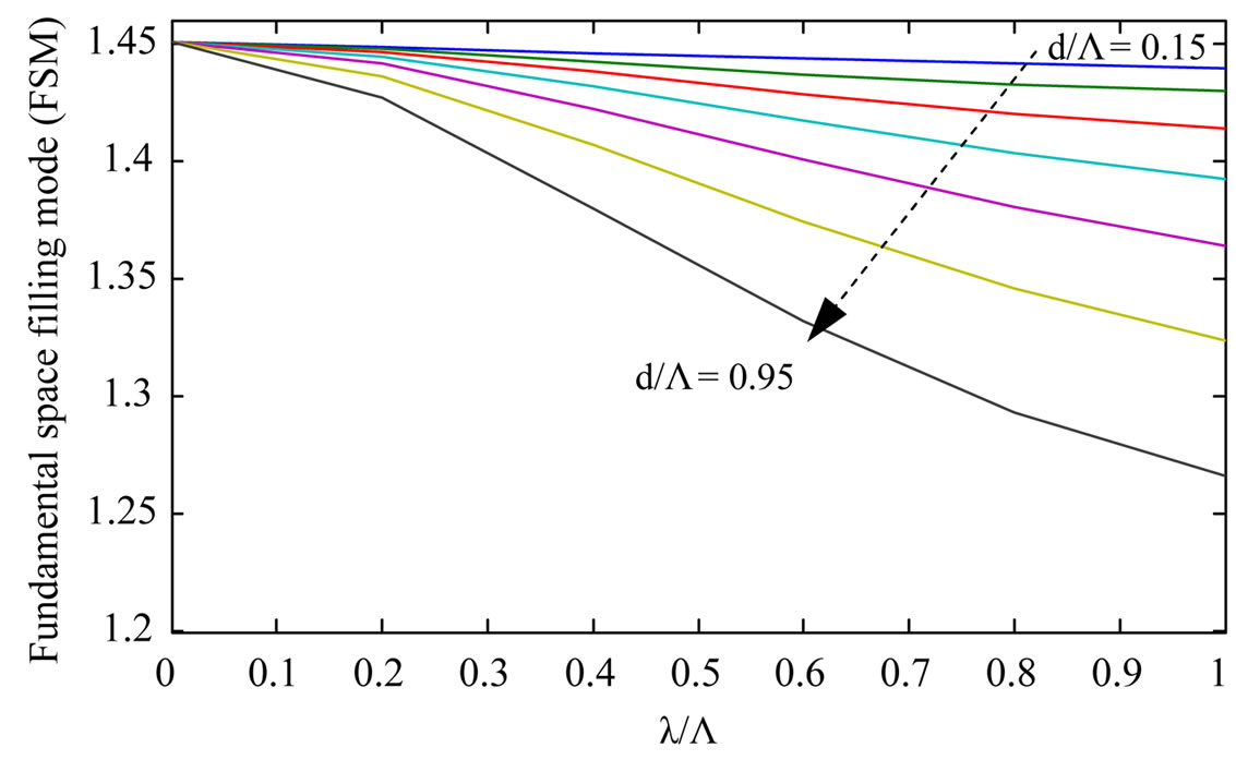 (b)
(b)
Figure 3. Effective indices for the core top (a), and fundamental space filling mode (FSM)-(b) modes for triangular photonic crystal fibers. The lines indicate different values of the hole diameter relative to the pitch. The lines correspond to different values of d/Λ, increasing by 0.1.

Figure 4. Grating period versus wavelength using IEIM.
wavelength that results. This means that the true spectral shift in wavelength can be calculated from the phasematching condition only if the effective refractive indices have been evaluated at the new resonant wavelength that is reached after the spectral shift has occurred as a result of the change in next. The sensitivity of the LPG was calculated by the evaluation of the effective propagation constant of cladding mode versus the external refractive index. Once the value of ambient refractive index reaches that of the cladding, discrete cladding modes are no longer guided along the fibre. This is evident in the absence of distinct attenuation bands in the LPG transmission spectrum at this point (the spectral properties are “washed out”) and broadband losses are visible due to lousy coupling with the continuum of radiation modes [33]. However when the index is greater than the index of silica, the fiber becomes as known as a leaky or hollow dielectric waveguide due to the fact that no total internal reflection exists, but rather Fresnel reflection occurs at the cladding external interface, and the portion of the light that is refracted to the surrounding material is lost from the fibre.
3. Modal Analysis of the PCFs by MMP
The CUDOS MOF software [22] is used to found both core and cladding mode by solving the transversal wave equation for the electric field:
 (3)
(3)
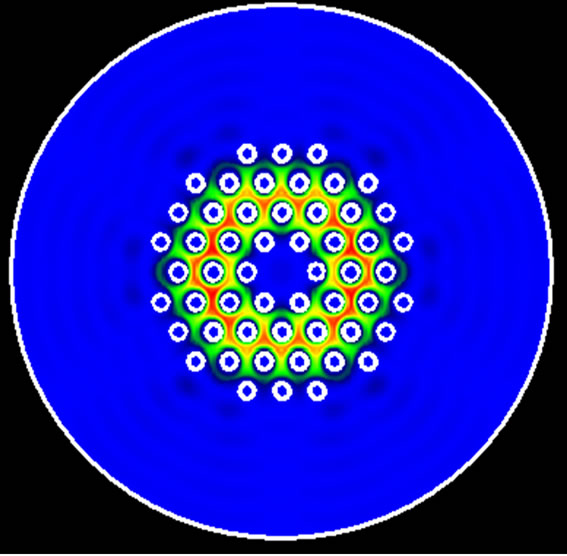
The grating period of the LPGs are taken to have 500 micrometer. On the other hand to obtain a stable solution for the cladding mode we have place the radius of the air layer contain around the cladding to the minimal value that gave stable solutions [34]. In developing this model we have assumed that the dispersion due to the core, cladding and its surrounding material are negligible and therefore have been ignored. In fact all modes are guided mostly through the silica, and the influence of the material dispersion on the effective index difference is negligible [19,35,36]. Figure 5 shows the field patterns of the fundamental mode (a) and the first cladding mode for different values of next. It is clearly noted from this figure that radiation losses increase when next become close to the cladding refractive index. In Figures 6 and 7 we report the resonant wavelength shifts and the sensitivity of the LPG fibre by using the IEIM and the MMP methods. Unless the resonance picks formed between the core mode and the first cladding mode is matched when the external index media is air, we observe that as the external refractive index increases the resonance picks calculated by IEIM shift away from the numerical value cal-
 (a)
(a) (b)
(b)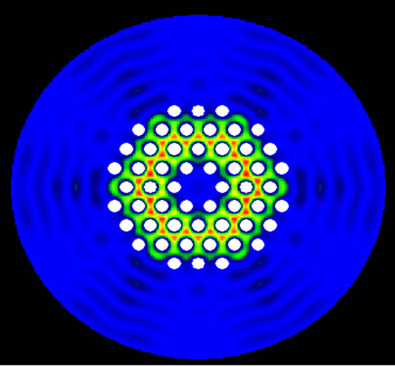 (c)
(c)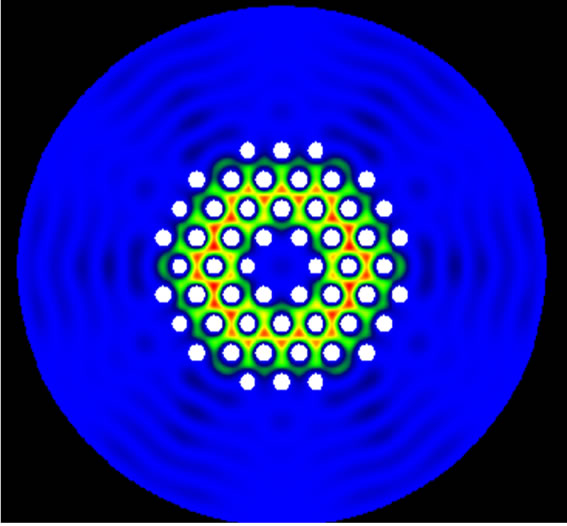 (d)
(d)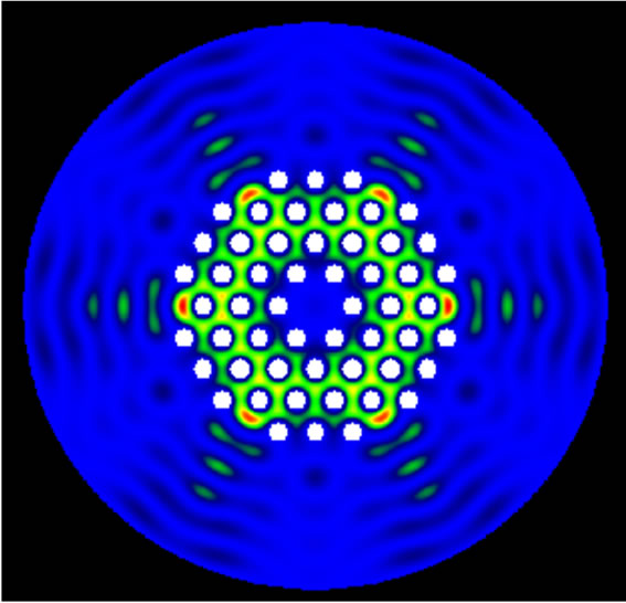 (e)
(e)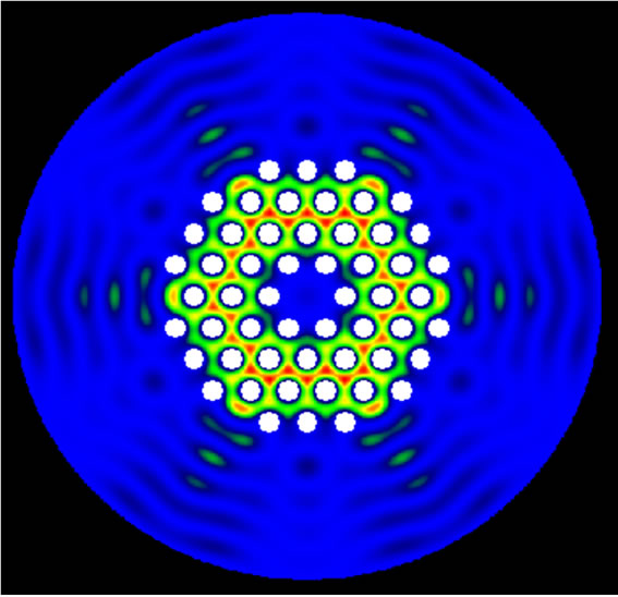 (f)
(f)
Figure 5. Profile of the first cladding mode for various external refractive index media (next). (a); Fundamental mode, (b, c, d, e, d); cladding mode for next = 1, 1.2, 1.3, 1.35, 1.4.
culated by MMP. This disagreement can be explained by the contribution of the non linear effect due to the interaction between cladding mode and external refractive index. This effect is clearly observed in Figures 6 and 7 which reflects that the ambient media plays a key role in the coupling with the cladding modes.
In fact, for LPG fibres the influence of the surrounding refractive index can be described by the following analytical expression:
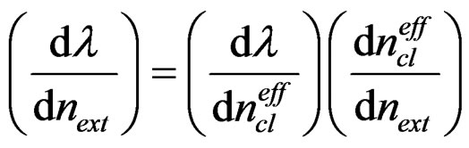
From this expression it can be easily anticipated that the spectral sensitivity presents a nonlinear behavior that is more pronounced as the surrounding refractive index become close to the cladding refractive index. This nonlinear behavior is not taken in to account in the IEIM
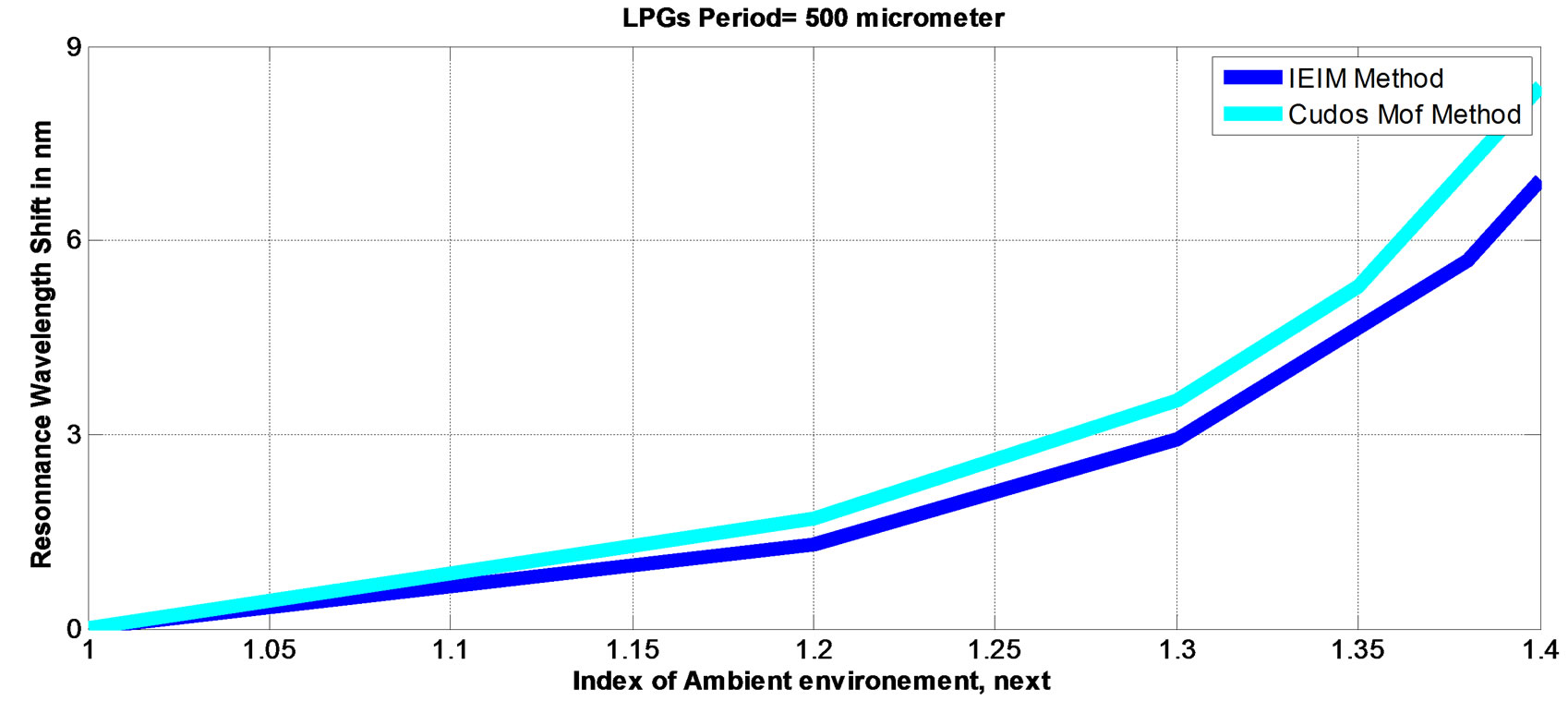
Figure 6. Calculation of the resonance shift Wavelength of the LPG-PCF.

Figure 7. Sensitivity of the LPG calculated by both Cudos and IEIM method.
approach which decreases the accuracy of this method.
So, the IEIM can be adopted to design a single mode fibre where the procedure of calculation of the resonance coupling between the core mode and the first cladding mode in an LPG is simple. It can also offer all information related to the performance of such sensor based on this type of symmetrical LPG.
To further analyse the performance of the IEIM method, we have calculated the sensitivities of the proposed device for two different wavelengths, as reported in table 1. From this table, it can be anticipated that the disagreement decreases by reducing the operating wavelength of the LPG-Sensor. Next, we have investigated the sensitivity of the fibre against hole diameter in order to understand its effect on the accuracy of IEIM method. The simulating results are reported in figure 8, from which, we can conclude that results obtained by last method become less accurate when the air hole diameter decreases. This can be explained by the fact that the values of the PCF radius vary as function of both d/Λ and the relative wavelength d, Λ.
4. Conclusion
In conclusion, the results of this work show that IEIM is a simple and promising method for obtaining modal characteristics and sensing properties of long period grating photonic crystal fibers (LPG-PCFs) when the surrounding media is assumed to be air. However, its accuracy decreases when the fiber is immersed into a liquid
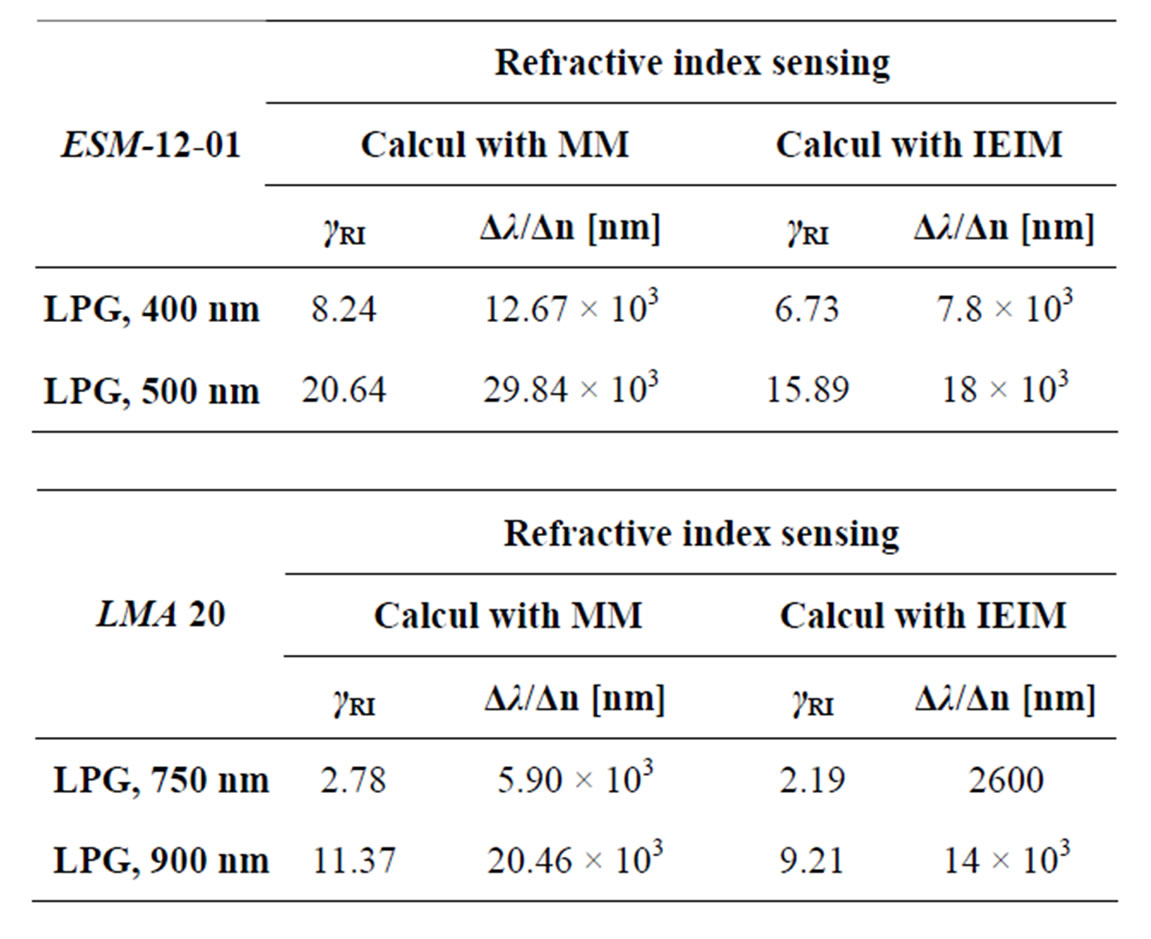
Table 1. Comparison of the sensitivity calculated with the two methods for the proposed LPG sensors against different wavelengths.
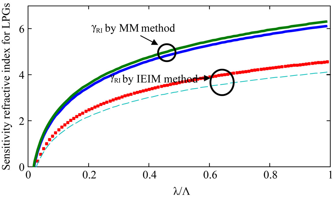
Figure 8. γRI for LPGs refractive index sensor. The lines indicate different values of the hole diameter relative to the pitch: 0.46 and 0.47 for wavelength 1 µm.
liquid having a refractive index close to that of the cladding.
5. Acknowledgements
The authors would like to thank Dr. Boris Kuhlmey and Dr. Maksim Skorobogatiy, for their contribution to this work.
REFERENCES
- H. A. Sotelo, Yu. O. Barmenkov and A. V. Kir’yanov, “The Use of Erbium Fiber Laser Relaxation Frequency for Sensing Refractive Index and Solute Concentration of Aqueous Solutions,” Laser Physics Letters, Vol. 5, No. 11, 2008, pp. 825-829. doi:10.1002/lapl.200810073
- V. Bhatia, M. K. Burford, K. A. Murphy and A. M. Vengsarkar, “Long-Period Fiber Grating Sensors,” OFC’96 Optical Fiber Communications, San Jose, 25 Feburary-1 March 1996, pp. 265-266. doi:10.1109/OFC.1996.908281
- C. C. Ye, S. W. James and R. P. Tatam, “Simultaneous temperature and Bend Sensing with Long-Period Fiber Gratings,” Optics Letters, vol. 25, No. 14, 2000, pp. 1007- 1009. doi:10.1364/OL.25.001007
- V. Bhatia, D. Campbell and R. O. Claus, “Simultaneous strain and Temperature Measurement with Long-Period Gratings,” Optics Letters, vol. 22, No. 9, 1997, pp. 648- 650. doi:10.1364/OL.22.000648
- H. J. Patrick, C. C. Chang, and S. T. Vohra, “Long period Fobre Gratings for Structural Bend Sensing,” Electronics Letters, vol. 34, No. 18, 1998, pp. 1773-1775. doi:10.1049/el:19981237
- W. Belhadj, F. AbdelMalek and H. Bouchriha, “Characterization and study of Photonic Crystal Fibres with bends,” Materials Science & Engineering C, Vol. 26, No. 2-3, 2006, pp. 578-579. doi:10.1016/j.msec.2005.10.004
- X. Shu and D. Huang, “Highly Sensitive Chemical Sensor Based on the measurement of the separation of Dual Resonant Peaks in a 100-µm-period fiber grating,” Optics Communications, vol. 171, No. 1-3, 1999, pp. 65-69. doi:10.1016/S0030-4018(99)00522-2
- T. Allsop, L. Zhang and I. Bennion, “Detection of Organic Aromatic Compounds in paraffin by a Long-Period Fiber Grating Optical Sensor with Optimized Sensitivity,” Optics Communications, vol. 191, No. 3-6, 2001, pp. 181-190. doi:10.1016/S0030-4018(01)01131-2
- R. Falate, R. C. Kamikawachi, M. Müller, H. J. Kalinowski and J. L. Fabris, “Fiber Optic Sensors for Hydrocarbon Detection,” Sensors and Actuators B: Chemical, vol. 105, No. 2, 2005, pp. 430-436. doi:10.1016/j.snb.2004.06.033
- H.-P. Loock, R. S. Brown, J. A. Barnes, N. R. Trefiak, K. L. Laugesen and G. Nemova, “Long Period Grating Sensor Methods and Apparatus,” US Patent no. 7391942, 2004.
- J. H. Chong, P. Shum, H. Haryono, A. Yohana, M. K. Rao, C. Lu and Y. N. Zhu, “Measurements of refractive Index Sensitivity Using Long-Period Grating Refractometer,” Optics Communications, Vol. 229, No. 1-6, 2004, pp. 65-69. doi:10.1016/j.optcom.2003.10.044
- L. Rindorf and O. Bang, “Highly Sensitive Refractometer with a Photonic-Crystal-Fiber Long-Period Grating,” Optics Letters, Vol. 33, No. 6, 2008, pp. 563-565. doi:10.1364/OL.33.000563
- D. K. C. Wu, B. T. Kuhlmey and B. J. Eggleton, “Ultrasensitive Photonic Crystal Fiber Refractive Index Sensor,” Optics Letters, Vol. 34, No. 3, 2009, pp. 322-324. doi:10.1364/OL.34.000322
- G. Kakarantzas, T. Birks and P. Russell, “Structural longPeriod Gratings in Photonic Crystal Fibers,” Optics Letters, Vol. 27, No. 12, 2002, pp. 1013-1015. doi:10.1364/OL.27.001013
- Y. Zhu, P. Shum, H.-J. Chong, M. K. Rao and C. Lu, “Strong resonance and a Highly Compact Longperiod Grating in a Large-Mode-Area Photonic Crystal Fiber,” Optics Express, Vol. 11 No. 16, 2003, pp. 1900-1905. doi:10.1364/OE.11.001900
- K. N. Park, T. Erdogan, K. S. Lee, “Cladding Mode Coupling in Long-Period Gratings Formed in Photonic Crystal Fibers,” Optics Communications, Vol. 266, No. 2, 2006, pp. 541-545. doi:10.1016/j.optcom.2006.05.056
- L. Rindorf and O. Bang, “Sensitivity of Photonic Crystal Fiber Grating Sensors: Biosensing, Refractive Index, Strain, and Temperature Sensing,” Journal of the Optical Society of America B, Vol. 25, No. 3, 2008, pp. 310-324. doi:10.1364/JOSAB.25.000310
- F. Brechet, J. Marcou, D. Pagnoux and P. Roy, “Complete analysis of the characteristics of propagation into photonic Crystal Fibers by the Finite Element Method,” Optical Fiber Technology, Vol. 6, No. 2, 2000, pp. 181- 191. doi:10.1006/ofte.1999.0320
- H. P. Uranus and H. J. W. M. Hoekstra, “Modeling of microstructured waveguides using a finite-element-based vectorial Mode Solver with Transparent Boundary Conditions,” Optics Express, Vol. 12, 2004, pp. 2795-2809.
- H. P. Uranus and H. J. W. M. Hoekstra, “Modelling of Microstructured Waveguides Using a Finiteelement-Based Vectorial Mode Solver with Transparent Boundary Conditions,” Optics Express, Vol. 12, No. 12, 2004, pp. 2795- 2809. doi:10.1364/OPEX.12.002795
- Y.-f. Li, C.-y. Wang and M.-l. Hu, “A Fully Vectorial Effective Index Method for Photonic Crystal Fibers: application to Dispersion Calculation,” Optics Communications, vol. 238, No. 1-3, 2004, pp. 29-33. doi:10.1016/j.optcom.2004.04.040
- CUDOS, “The University of Sydney ARC Centre of Excellence, School of Physics,” www.physics.usyd.edu.au/cudos/mofsoftware
- K. wang N. Park, T. Erdogan, K. yung and S. Lee, “Cladding Mode Coupling in long Period Gratings Formed in Photonic Crystal Fibers,” Optics Communications, Vol. 266, No. 2, 2006, pp. 541-545. doi:10.1016/j.optcom.2006.05.056
- K. N. Park and K. S. Lee, “Improved Effective-Index Method for analysis of Photonic Crystal Fibers,” Optics Letters, Vol. 30, No. 9, 2005, pp. 958-960. doi:10.1364/OL.30.000958
- T. Erdogan and J. Lightwave, “Fiber grating spectra,” Journal of Lightwave Technology, Vol. 15, No. 8, 1997, pp. 1277-1294. doi:10.1109/50.618322
- S. W. James and R. P. Tatam, “Optical Fibre Long-Period Grating Sensors: Characteristics and application,” Measurement Science and Technology, Vol. 14, No. 5, 2003, pp. R49-R61. doi:10.1088/0957-0233/14/5/201
- A. M. Vengsarkar, P. J. Lemaire, J. B. Judkins, V. Bhatia, T. Erdogan and J. E. Sipe, “Long Period Fiber Gratings as Band-Rejection Filters,” Journal of Lightwave Technology, Vol. 14, No. 1, 1996, pp. 58-64. doi:10.1109/50.476137
- V. Bhatia, “Applications of Long-Period Gratings to single and Multi-Parameter Sensing,” Optics Express, Vol. 4, No. 1, 1999, pp. 457-466. doi:10.1364/OE.4.000457
- H. J. Patrick, A. D. Kersey and F. Bucholtz, “Analysis of the response of Long Period Fiber Gratings to external index of refraction,” Journal of Lightwave Technology, Vol. 16, No. 9, 1998, pp. 1606-1612. doi:10.1109/50.712243
- Y. n. Zhu, Z. h. He and H. Du, “Detection of External Refractive Index Change with High Sensitivity Using Long-Period Gratings in Photonic Crystal Fiber,” Sensors and Actuators B, Vol. 131, No. 1, 2008, pp. 265-269. doi:10.1016/j.snb.2007.11.040
- I. Del Villar, M. Achaerandio, I. R. Matias and F. J. Arregui, “Deposition of overlays by electrostatic Self-Assembly in Long-Period Fiber Gratings,” Optics Letters, Vol. 30, No. 7, 2005, pp. 720-722. doi:10.1364/OL.30.000720
- Blaze Photonics, Endlessly Single Mode PCF: ESM-12- 01. http://www.blazephtonics.com/pdf/ESM%20-%2012%20-%2001.pdf
- J. S. Petrovic, H. Dobb, V. K. Mezentsev and K. Kalli “Sensitivity of LPGs in PCFs Fabricated by an Electric Arc to Temperature, Strain, and External Refractive Index,” Journal of Lightwave Technology, Vol. 25, No. 5, 2007, pp. 1306-1312. doi:10.1109/JLT.2007.893912
- P. R. McIsaac, “Symmetry-Induced Modal Characteristics of Uniform Waveguides—I: Summary of Results,” IEEE Transactions on Microwave Theory and Techniques, Vol. 23, No. 5, 1975, pp. 421-429. doi:10.1109/TMTT.1975.1128584
- T. W. MacDougall, S. Pilevar, C. W. Haggans and M. A. Jackson, “Generalized expression for the growth of Long Period Gratings,” IEEE Photonics Technology Letters, vol. 10, no. 10, 1998, pp. 1449-1451. doi:10.1109/68.720290
- X. Shu, L. Zhang and I. Bennion, “Sensitivity characteristic of long Period Fibre Gratings,” Journal of Lightwave Technology, vol. 20, no. 2, 2002, pp. 255-266. doi:10.1109/50.983240
NOTES
*Corresponding author.