Energy and Power Engineering
Vol.5 No.3(2013), Article ID:31272,8 pages DOI:10.4236/epe.2013.53026
Study of Lightning Safety Distance Using Rolling Sphere Method
Electrical & Electronics Engineering Department, Universiti Teknologi PETRONAS, Tronoh, Malaysia
Email: norzaihar_yahaya@petronas.com, akhmalbe@gmail.com
Copyright © 2013 Nor Zaihar Yahaya, Mohd Akhmal Daud. This is an open access article distributed under the Creative Commons Attribution License, which permits unrestricted use, distribution, and reproduction in any medium, provided the original work is properly cited.
Received February 5, 2013; revised March 7, 2013; accepted March 22, 2013
Keywords: Lightning Protection System (LPS); Rolling Sphere Method (RSM); Striking Distance
ABSTRACT
The development of a computer program for evaluation of lightning safety distance between the tower and satellite dish is written in M-File MATLAB. The 3-dimensional illustrative graphics model is used to capture better understanding on how lightning protection system (LPS) works. The study of physical length of grounding electrode used on the tower is found to be significantly affecting the grounding system performances where they depend on magnitude of dispersed lightning strikes current and the settling time for the current to completely disperse. The grounding system performance is studied by using lightning impulse current (LIC) generator, simulated in OrCad PSpice software. It is found that the optimum length of vertical lightning rod in LPS is the same with the striking distance. There is no significant improvement is observed in lightning safety distance if the length of vertical lightning rod is higher than striking distance. The lightning strike peak current that has larger magnitude than the withstanding insulation level of specified object causes no physical damage. It is because the lightning safety distance increases when the lightning strike peak current becomes higher. It is also found that the lower grounding impedance generates higher magnitude of dispersed peak current and faster settling time.
1. Introduction
The lightning protection system (LPS) relies upon the application of the physics of electrical discharges. It is needed to protect the electrical and electronic equipment against the lightning strikes, for example the telecommunication tower. There are two types of subsystems in designing conventional LPS. The first subsystem is called air termination system which consists of natural conductive components in vertical form of structure from the horizontal ground level surface, also known as lightning rod. The protection zone of LPS is defined as the volume of space where the air termination provides protection against a direct lightning strike by attracting the strike to it. The Rolling Sphere Method (RSM) is based on Electro-geometric Model (EGM) which is one of the techniques used to determine the lightning safety distance. The striking distance is the total distance of the lightning strikes to the rod. It can be determined using the amplitude of lightning strike peak current. There is another protection method called the Cone Protection Method. However, this method yields inaccurate results and has low protection efficiency [1,2].
The second subsystem is called earth termination system used to conduct the lightning strike current from the air termination system to the ground by connecting downward conductors to a grounding cylinder electrode. The grounding electrode is important as it keeps the enclosure voltage of the equipment to be equal to the earth potential [3]. The amount of magnitude of dispersed lightning peak current is affected by the grounding impedance values. In fact, it is influenced by the characteristics of water or soil resistivity and length of grounding electrode.
This paper aims to investigate and determine the new lightning safety distance based on level I lightning protection standard according to IEC 61024-1. The computer software will demonstrate the distance and illustrate the LPS scheme operation. In addition, the performance of grounding system will also be investigated based on grounding input impedance. The findings are expected to deliver the best grounding system with higher dispersed lightning peak current and faster settling time.
2. Lightning Protection System Scheme
2.1. Lightning Safety Zone Using RSM
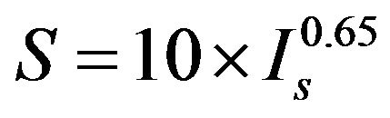
Figure 1 shows the concept of RSM technique for LPS scheme. The protection zone can be visualized as the surface of a sphere with radius striking distance, S is rolled toward the mast. This concept has led to the given rolling sphere scheme for simplified Electro-geometric Model [5]. The striking distance, S with respect to lightning strike peak current, Is is calculated by using (1).
Here, the equipment will be protected under the boundary of protected zone. The horizontal ground safety radius, Rg for height of lightning rod, h1 is governed by (2).
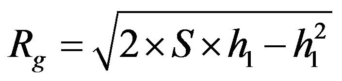 (2)
(2)
The lightning object safety radius, Ro for height of object, h2 is given by using (3).
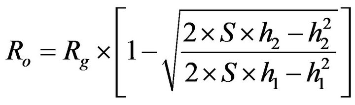 (3)
(3)
From (3), the vertical lightning rod that has a radius equals to its striking distance will attract the stepped leader. The Is that is discharged at a distance away from S will be grounded to the ground.
Table 1 shows the lightning protection standard based on International Electro-technical Commission (IEC 61024-1), where the protection levels can be interpreted as level I, level II, level III and level IV. The maximum Is in each level is given by 2.9 kA, 5.4 kA, 10.1 kA and 15.7 kA respectively. This eventually gives the lightning interception efficiency at 99%, 97%, 91% and 84% respectively. By adopting the IEC 61024-1 standard, the lightning safety distance can be calculated using the level of protection required.
2.2. Grounding System Performances Based on Termination Impedance
Figure 2 shows the typical grounding electrode used in
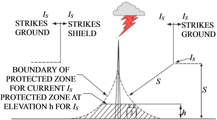
Figure 1. Lightning protection zone area by RSM technique [4].
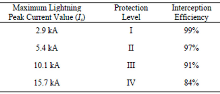
Table 1. EC 61024-1 lightning protection standard [6].
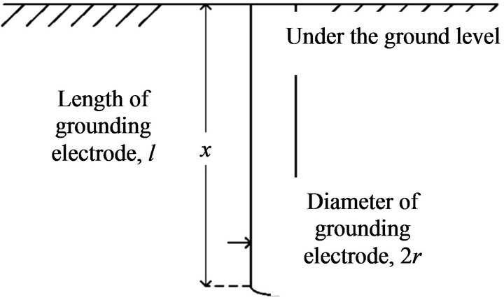
Figure 2. The grounding electrode.
this study where the grounding impedance will be affected by soil or water resistivity [7]. Nevertheless, there are also other criteria that can influent the grounding impedance such as length of grounding electrode, l, the radius of grounding electrode, r and also the burial depth of grounding electrode, t. The grounding impedance, ZA is given by using (4).
 (4)
(4)
3. Design Issue
In order to design a direct stroke shielding system for satellite dish, the engineer must consider several elusive factors inherent in lightning phenomena. The factors are:
• The magnitude of lightning strikes peak current is unpredictable.
• The complexity and cost of the solution involved to analyze a lightning protection system design in detail.
The unavailability data of lightning strikes occurrences and its frequency at telecommunication station. In the real application of LPS, there is no known method that can be providing 100% safety protection against the lightning strikes. The uncertainty, complexity, and cost of performing a detailed analysis of the LPS have historically resulted in simple rules of thumb being utilized in the design. In order to design the LPS, the four-step approach is suggested:
• Select an appropriate design method and lay out the LPS configuration.
• Evaluate the cost of the solution and effectiveness of the resulting design.
• Evaluate the significant and value of the facility being protected.
• Investigate and analyze the frequency of lightning strikes occurrences at the facility that required protection.
3.1. Configuration of Existing Protection System
Figure 3 shows the configuration of existing protection system. It can be seen that the lightning safety distance between the tower (height of 20 m) and satellite dish is 30 m. This arrangement can be interpreted as a level III lightning protection standard according to the IEC 61024-1. It is found that the interception efficiency of the LPS is 91%.
Therefore, the new distance arrangement should provide the highest level of protection to reduce the possibility of satellite dish failure due to lightning strike. Also, the existing ZA at the tower is determined as 15 Ω. This value is usually recommended to be in between 1 Ω and 10 Ω based on water or soil resistivity [6].
4. Methodology
4.1. Lightning Safety Distance
Equations (1)-(3) are used to find the new lightning safety distance for satellite dish. To do this, the programming script is built in M-File Matlab software to allow users to key in the necessary inputs data before the result of lightning safety distance can be simulated. The required input parameters are:
• The, IS based on IEC 61024-1 Lightning Protection Standard in Table 1.
• The h1.
The dimensions of protected object include height, h2, width, w2 and length, l2.
Table 2 shows the parameters to be studied in finding their relationship with the lightning safety distance. The
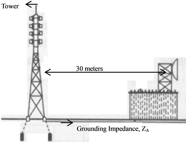
Figure 3. Existing configuration at telecommunication station.
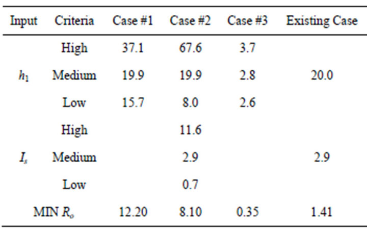
Table 2. Set of parameters for lightning safety distance.
input parameters are h1 and Is. Here, the LPS will be protected if Ro is larger than the MIN Ro or vice versa.
4.2. Grounding System
Table 3 shows the values of ZA used in this work. The low, medium and high length of grounding electrodes are 10 m, 100 m and 350 m respectively. The calculation of ZA is based on Equation (4). Each of ZA value will be applied into the lightning impulse current (LIC) generator. The height of grounding electrode value is adjusted to let ZA become lower than 10 Ω. Other constant parameters used are r and t of 0.004 m and 0.5 m respectively.
Figure 4 shows the R-L-C circuit diagram used to produce the natural lightning waveform characteristics [8,9]. Using this circuit, the grounding impedance will be applied to analyze the performance of the grounding system.
5. Results & Discussions
Figure 5 shows the relationship between Ro, Is and h1. The Ro increases when the lightning strike current is larger than Is in all cases. For an example in case #1, the Ro of high current Is (11.6 kA) is 27.8678 m whilst for the medium current Is (2.9 kA) is 12.6311 m. The result shows that Ro of high current Is has wider coverage than the medium current and therefore the object is securely protected. Nevertheless, Ro decreases when the lightning strike current is smaller than the medium current Is for all cases. In case #1, the Ro of low current Is (0.7 kA) is 3.4312 m and for the medium current is 12.6311 m. The result shows that Ro of low current Is is smaller than the medium current. Here, the object lies out of the protection region and hence prone to lightning strikes. However, if the value of medium current Is was selected based on the withstand insulation level of specified object, low current Is should cause no damage to the equipment.
Figure 6 shows the relationship between Ro and h1. As for case #1, the Ro of high lightning rod (37.1 m) is
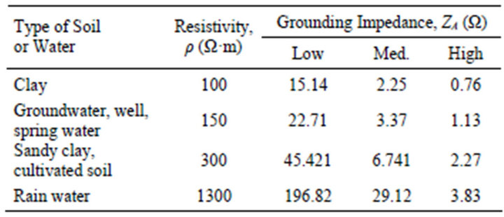
Table 3. Grounding impedance values depending on the type of soil or water resistivity.
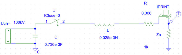
Figure 4. LCI generator with grounding impedance insertion.
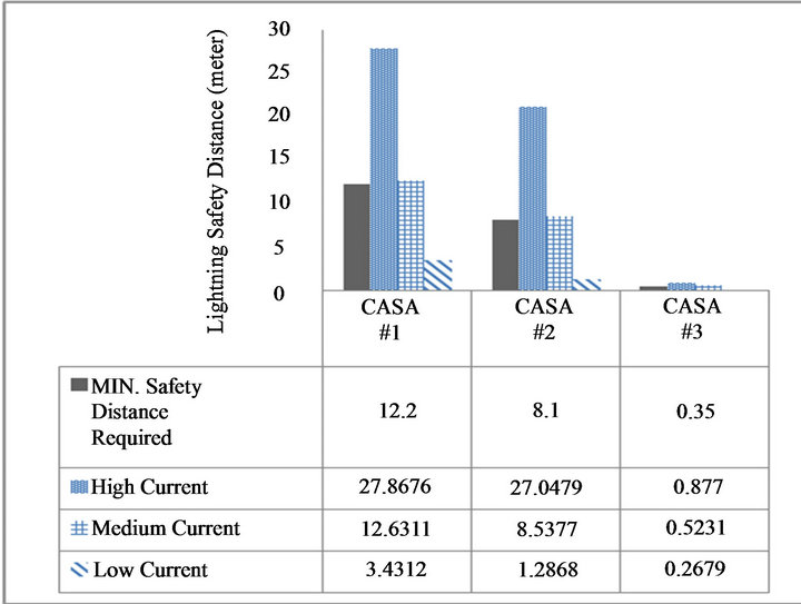
Figure 5. Lightning safety distance, Ro versus lightning strike peak current, Is.
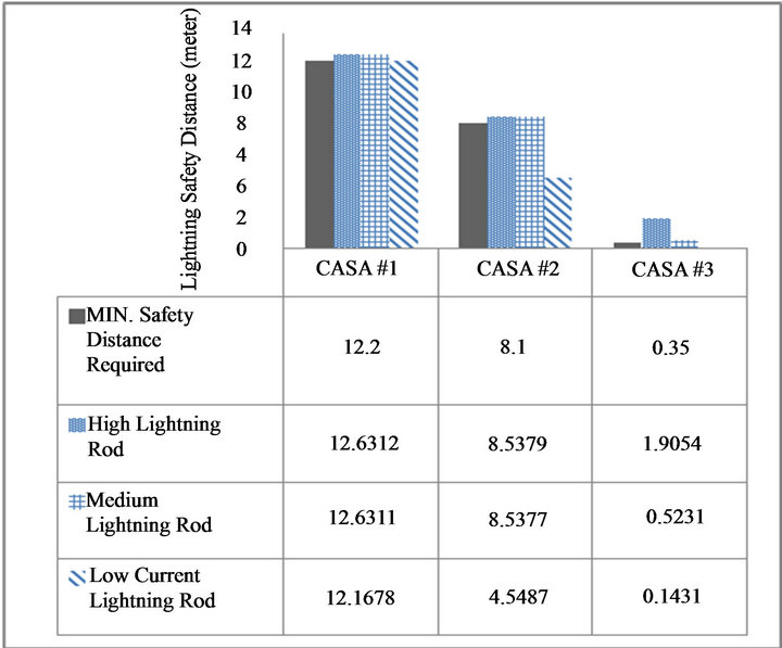
Figure 6. Lightning safety distance, Ro versus length of lightning rod, h1.
12.6312 m while for the medium lightning rod (19.9 m) is 12.6311 m. This small difference in Ro indicates that in order to be protected, at least the medium length of lightning rod must be applied. The object will not be secured for a lower length (15.7 m). The same explanation goes for case # 2 and case # 3.
5.1. Comparative Assessments
Figure 7 shows the existing Ro of satellite dish, based on Level III protection. The interception efficiency level is 91 %. As shown in the figure, the Ro at the telecommunication station is 30 m. Since the satellite dish is vulnerable to lightning strike, higher safety level of protection is need to be implemented. This can be improved by using Level I.
Figure 8 shows the improved Ro of satellite dish, using Level I protection system. The new Ro is 11.27 m. It has closer distance compared to Figure 7. The Ro is reduced by 62.43% indicating an improvement. Hence, the tower has then been equipped with the 99 % of lightning interception efficiency.
5.2. Grounding System Assessments
Figure 9 shows that the relationship between the dispersed lightning peak current, Ids and length of electrode, l. The resistivity, ρ (Ω·m) depends on the type of soil or water. Using l of 350 m, this makes ZA to be less than 10 Ω and hence gives result in highest Ids. As an example for the clay resistivity, the Ids is found to be 82.285 kA compared to 37.431 kA and 6.441 kA in medium (100 m) and low (10 m) electrode length respectively. Therefore, the amount of dispersed lightning peak current is proportional to the length of electrode. This shows that a lower ZA will make Ids larger and hence better grounding system.
Figure 10 shows the relationship between the settling time, ts for lightning current dispersal, and length of electrode, l. In the analysis, the ts will become longer (slower speed) when l of 350 m is used, for instance in clay, the ts is given as 907.2 ms. This indicates that the ts is inversely proportional to l. Therefore, the low ZA and l values are preferred to make the ts shorter ie completely disperse lightning current faster.
Figure 11 illustrates the Is by using ZA of 15 Ω. The simulated waveform indicates that the amount of Ids is 6.5 kA. In addition, the ts is determined as 98.421 ms. Figure 12 shows the magnitude of Ids using ZA = 0.004 Ω. Here the Ids shows and increase in current of 196.471 kA with faster ts of just 2.3684 ms. This satisfies the expectation in the hypothesis.
Thus, in order to produce the ZA smaller than 10 Ω, the ρ of items and l need to be considered. It is found that the lower ZA will make the grounding system performance
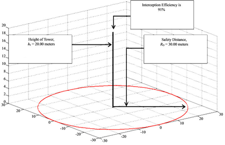
Figure 7. Existing LPS configuration.
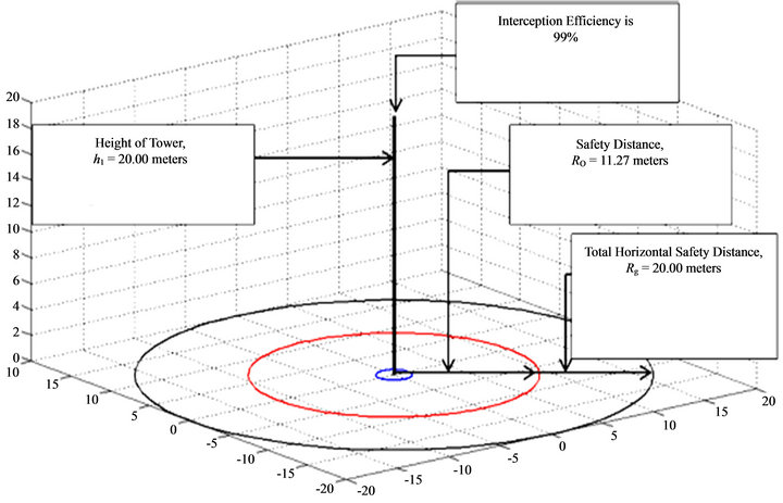
Figure 8. Improved LPS configuration.
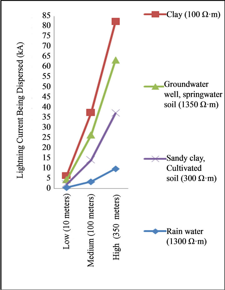
Figure 9. Dispersed peak lightning current, Ids versus type and length of electrode, l.

Figure 10. Settling time, ts versus length of electrode, l.
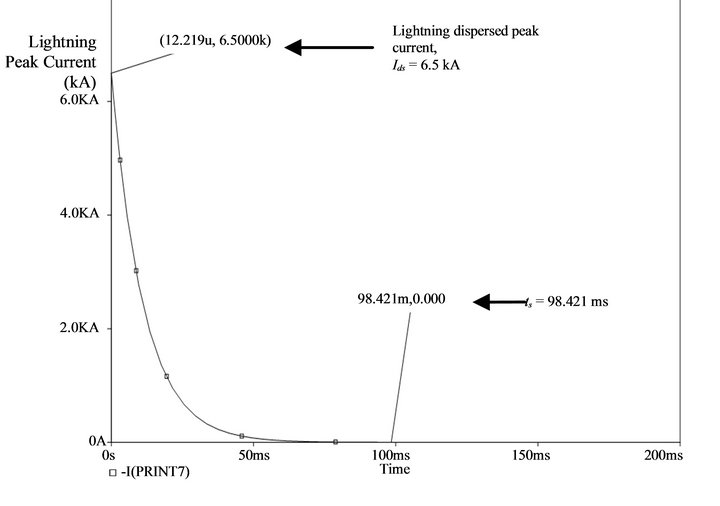
Figure 11. Lightning impulse current (LIC) with 15 Ω grounding impedance, ZA.
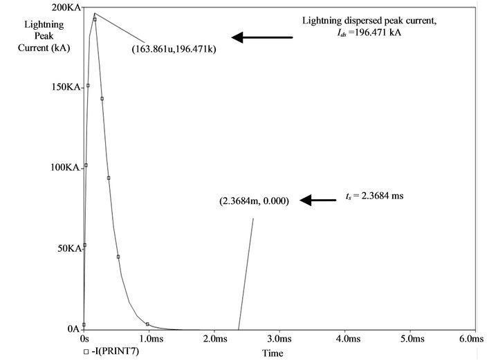
Figure 12. Lightning impulse current (LIC) with 0.004 Ω grounding impedance, ZA.
becomes better. In addition, when the lower ZA is used, the magnitude of Ids becomes higher and hence makes the ts for Ids to completely disperse faster.
6. Conclusions
This work has produced the simulation results about the lightning protection system based on International Electro-technical Commission (IEC 61024-1) standard. The results are summarized as follow:
• Generally, the optimum length of lightning vertical rod should be the same with the striking distance.
• The striking distance will extend when the peak current magnitude of lightning strike gets bigger. This will improve the lightning safety distance and eventually protect the object.
• Low grounding impedance can be produced by having longer grounding electrode and low resistivity in the soil or water. Hence, this makes the grounding capability better.
The new LPS configuration using rolling sphere method has improved the lightning interception efficiency by 8%. It is found that the new lightning safety distance between tower and satellite dish with level I has been reduced by 62.43%. This also applies to the grounding impedance where the improvement to 99.97% is monitored having more lightning peak current being dispersed up to 96.69%. In addition, the lightning strike current has dispersed completely faster having a remarkable speed increase by 97.59%.
7. Acknowledgements
The authors would like to thank Universiti Teknologi PETRONAS for providing financial support to publish this work.
REFERENCES
- P. Y. Okyere and E. George, “Evaluation of Rolling Sphere Method Using Leader Potential Concept: A Case Study,” IJME-INTERTECH Conference, 2006, pp. 1-20.
- E. M. Thomson, “A Critical Assessment of the US Code for Lightning Protection,” IEEE Transaction on Electromagnetic Compatibility, Vol. 33, No. 2, 991, pp. 132-138. doi:10.1109/15.78350
- A. Ametani, H. Morii, T. Kubo and T. Chikaraa, “Impedance Characteristics of Grounding Electrodes on Earth Surface,” Electric Power Systems Research, Vol. 85, 2012, pp. 38-43. doi:10.1016/j.epsr.2011.07.006
- S. N. Robert, “Guide for Direct Lightning Stroke Shielding of Substations,” Georgia Power Company, Atlanta, 2007.
- A. C. Liew and C. M. Gui, “Performance Assessment of Lightning Shielding Systems,” IEEE Industry Applications Society Annual Meeting, Vol. 2, Seattle, 7-12 October 1990, pp. 1989-1994.
- C. Vernon, “Lightning Protections,” The Institution of Engineering and Technology, Stevenage, 2010.
- H. Motoyama, “Experimental and Analytical Studies on Lightning Surge Characteristics of a Burial Bare Wire,” IEEJ Transactions on Power and Energy, Vol. 126, No. 5, 2008, pp. 556-561.
- M. Gamlin, “Impulse Current Testing,” Lightning Protection Forum, Shanghai, June 2004, pp. 1-7.
- M. S. Kamarudin, E. Sulaiman, M. Z. Ahmad, S. A. Zulkifli and A. F. Othman, “Impulse Generator and Lightning Characteristics Simulation Using Orcad PSpice Software,” Engineering Conference, Kuching, 18-19 December 2008, pp. 1032-1037.