Energy and Power Engineering
Vol. 4 No. 4 (2012) , Article ID: 20222 , 7 pages DOI:10.4236/epe.2012.44033
Finite Element Analysis of Dynamic Damper for CV Joint
1Department of Mechanical Engineering, M.E.S. College of Engineering, Pune, India
2Department of Production Engineering, S.G.G.S. Institute of Engineering and Technology, Nanded, India
Email: yerrawar@mescoepune.org
Received March 14, 2012; revised April 20, 2012; accepted May 11, 2012
Keywords: Constant Velocity (CV); Finite Element Analysis (FEA)
ABSTRACT
Constant Velocity (CV) Joints are one of the most important components of front wheel drive axles. It is subjected to various stresses such as bending stress, shear stress and bearing stress. Apart from these stresses, it is also subjected to vibrations, due to out of balance tire or wheel and an out of round tire or wheel, or a bent rim. The main objective of this work is to reduce the stiffness of the damper, so that the damper can withstand within the required constraints (i.e. the forced frequency range of 80 Hz to 150 Hz). The free vibrational and forced vibrational effects are investigated to predict the resonance phenomenon of the damper. Finite Element Analysis in ANSYS-11 software was performed to predict the dynamic behavior of the system under the required vibrational frequencies ranging from 80 Hz to 150 Hz at given loading conditions.
1. Introduction
The drive axle assembly transmits torque from the engine and transmission to drive the vehicle’s wheels. Front wheel drive axles transfer engine torque from the transaxle’s differential to the front wheel. One of the important components of front wheel drive axles is the constant velocity joint as shown in Figure 1. These joints are used to transfer uniform torque at a constant speed while operating through wide range of angles.
A damper is used to minimize the structure borne energy that is present in a system from being converted to sound. When system vibrates at a resonance, a damper reduces the amplitude of vibrations, which in turn results in less sound radiation. The additional mass of a damper may help to change the resonant frequency and thereby aid in reducing damping. Equal length shafts are used in vehicle to help to reduce torque steer, the tendency to steer to one side as engine power is applied. For this application intermediate shaft is used as a link from transaxle to one of the half shaft. This intermediate shaft can use an ordinary universal joint to a yoke at the transaxle. At the outer end is having a support bracket and a bearing assembly. Looseness in the bearing or bracket can create vibrations. A damper weight called as dynamic damper is attached to one half shafts serves to dampen harmonic vibration in the drive train and to stabilize the shaft as it spins [1].
With front wheel drives the force produced by engine is transferred through gear box and then to the constant velocity drive shafts to the wheels. As per [2] it has been found that CV Joints significantly improves the performance of driveshaft in which CV Joints for Light Truck drive shafts have to meet the specific requirement for this vehicle. A Service-free life of 150,000 miles is standard for the Light Truck market segment and the joints have to be designed and sized accordingly. Torque, speed and angle define the operating envelope of a CV Joint and the durability is determined by the loads transmitted and the numbers of revolutions during its life. As per [3] it is clear that in the absence of prototypes, analytical methods such as finite element analysis are very useful in resolving noise and vibration problems by predicting dynamic behavior of the automotive component and systems.
The crank dampers which were implemented on engine damper in dual mode state, frequencies were defined by using transmissibility ratio to simplify the test process and eliminate effects of boundary conditions [4]. To verify the effectiveness of the damper, the engine dyno and vehicle road tests were conducted. The results show that dual mode dampers cannot substantially reduce airborne noise. As per [5] the steering motion and the movement of the engine and the wheels drive shaft provide the compensation for the length change and achieve the required articulation angle. Whereas as per [6] the practical
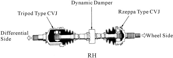
Figure 1. Constant velocity (CV) Joints.
vehicle designers constantly faced with the fact that vehicles live in an environment full of sources of vibratory excitation, which was overcome by using real life elastomers as spring elements by including temperature sensitivity, material damping and nonlinearity. Tetsuji Morita [7] investigated the influence of a dynamic damper pulley that can decrease the vibration amplitudes in the axial direction. The equilibrium equations for the entire body ware obtained by combining the equilibrium equation for the individual elements in such a way that the continuity of displacements was preserved at their interconnecting nodes.
In this paper analysis of a Damper which was mounted on half shaft in which a tripod type constant velocity joint was fitted on differential side and a Rzeppa type constant velocity joint was fitted on wheel side as shown in Figure 1 is studied. Modal as well as harmonic analysis for contact condition is performed by using Ansys work bench.
2. Problem Definition & Objective
In this work problem is of modifying the existing damper of front wheel drive vehicles for CV Joints in such a way that it should work within the forced frequency range of 80 Hz to 150 Hz, so that the optimum stiffness of the modified damper can be obtained. The dynamic damper currently available has stiffness 5 MPa to 25 MPa. In this work damper stiffness varies from 7 MPa to 24 MPa where the natural frequencies and shape modes as well as harmonic vibrations along required direction are need to be find.
The objective of this work is to analyze the dynamic damper using Finite Element Method to obtain the optimum stiffness of the damper at which it can withstand within the required constrains (Table 1).
3. Solid Modeling of Damper
To perform FE analysis of any component, the solid model of the same is essential. It is also called body in white. Figures 2 and 3 show a solid model of damper.
4. Finite Element Analysis Procedure
Dynamic Damper first modeled in PRO/E WILDFIRE which is excellent CAD software, which makes modeling
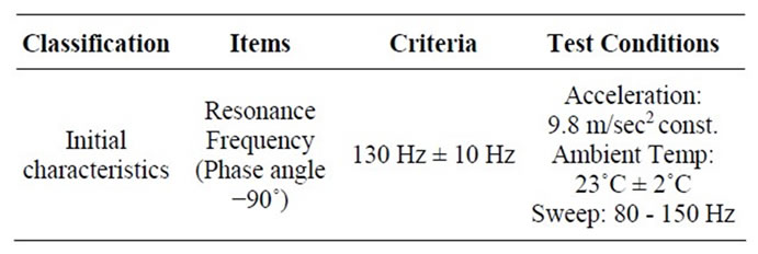
Table 1. Specification sheet.
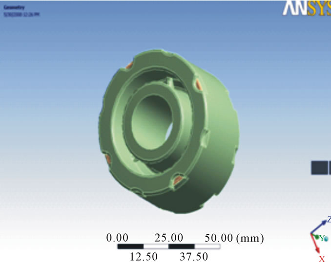
Figure 2. Solid model of damper.
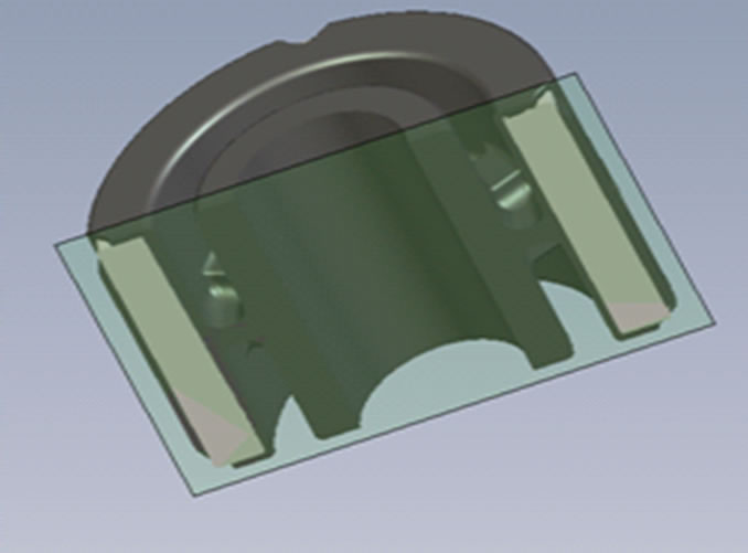
Figure 3. Cross section model of damper.
so easy and user friendly. The model is then transferred in IGES format and exported into the Analysis software ANSYS 11.0. The damper is analyzed in ANSYS in three steps. First is preprocessing which involves modeling, geometric clean up, element property definition and meshing. Next comes, solution which involves imposing boundary conditions and applying loads on the model and then solution runs. Next in sequence comes post processing, which involves analyzing the results plotting different parameters like stress, strain, natural frequency, harmonic frequency and many. The step by step procedure involved in the analysis is shown in Figure 4.
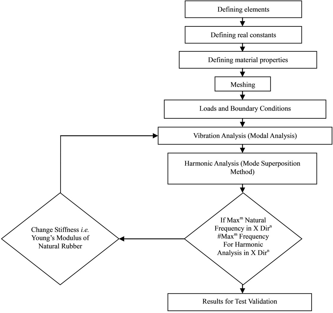
Figure 4. Finite element analysis procedure.
4.1. Finite Element Mesh Generation and Contact Element Type
The objective in building a solid model is to mesh that model with nodes and elements. Once the creation of solid model completed, set element attributes and establishing meshing controls, which turn the ANSYS program to generate the finite element mesh. For defining the elements attributes, the user has to select the correct element type. This is most important task in finite element analysis because it decides the accuracy and computational time of analysis.
In this work Solid 186 and Solid 187 elements are used as element type as shown in Table 2. Solid 186 Structural Solid is well suited to modeling irregular meshes. The element may have any work orientation. In this work Solid 186 structural solid is used for meshing of steel ring inside rubber of damper. A Solid 187 element is a higher order 3-D, 10-node element and it has a quadratic displacement behavior and is well suited to modeling irregular meshes. In this work Solid 187 solid is used for meshing of body of rubber of damper. The type of meshing used for damper is FREE mesh which is controlled by two parameters assigned to each mesh surface or volume that affect the size the elements generated. The meshed model and contact region is shown in Figure 5.
The steel ring which is inside the damper is in contact with the rubber compound. For performing the analysis it is important to generate the contact between these points and rest of the geometry. For generating the contact, contact pair has to be created. For the generation of the contact pair two types of contact elements are used and they are TARGET 170, CONTACT175.The numbers of contact elements generated are 5558 in which CONTA175 are 2779 and TARGE170 are 2779 as shown in Figure 6.
4.2. Loading and Boundary Conditions
Load is given as per specification sheet (Table 1). Loading is often in terms of velocities or acceleration. If desired, acceleration can be used to simulate gravity (by using inertial effects) by accelerating a structure in the direction opposite of gravity (the natural phenomenon). That is, accelerating a structure vertically upwards at 9.80665 m/s2. For boundary condition cylindrical support

Table 2. Details of FE element.
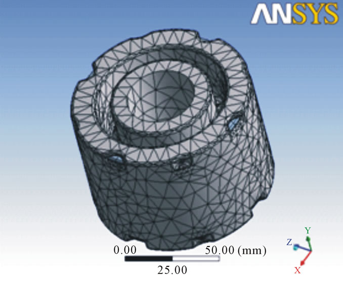
Figure 5. Meshed model of damper.
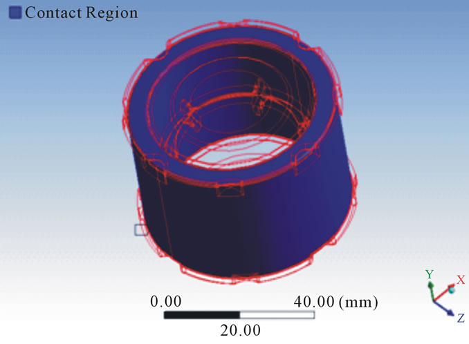
Figure 6. Contact elements in damper.
is used. For 3-D simulations, prevents one or more cylindrical faces from moving or deforming in combinations of radial, axial, or tangential directions. Loading and boundary condition shown in Figure 7. For modal analysis only cylindrical support is given as boundary condition which is given to inside rubber compound of a damper. Where as for harmonic analysis acceleration in X direction given as a boundary condition.
4.3. Modal Analysis
A modal analysis determines the vibration characteristics (natural frequencies and mode shapes) of a structure or a machine component. Modal analysis is based on the fact
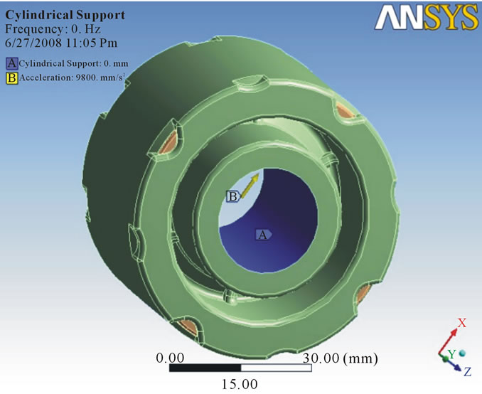
Figure 7. Loading and boundary condition.
that the vibration response of a linear time variant dynamic system can be expressed as the linear combination of the set of simple harmonic motions called as the natural modes of vibration. The value of natural frequency should always be greater than forced frequency so that there will be no condition of resonance. In this analysis, six modes were investigated to know the vibration characteristic of damper and from each mode shape the direction in which maximum deformation occurs was found out. After running the solution, natural frequency in X direction was found out. For 25 MPa stiffness, it was observed maximum frequency in X direction as 244.68 Hz (Figure 8) whereas for 24 MPa maximum frequency was 239.74 Hz (Figure 9). For 23 MPa and 22 MPa frequency was observed as 239.74 Hz (Figure 10) and 229.53 Hz (Figure 11) respectively. After that natural frequency for 15 MPa frequency was observed as 189.53 Hz (Figure 12). For stiffness 9 MPa and 8 MPa natural frequency in X direction was found as 146.82 Hz (Figure 13) and 138.42 Hz (Figure 14). At the last maximum natural frequency in X direction was observed as 129.48 Hz (Figure 15). The above results are summarized in Table 3.
4.4. Harmonic Response Analysis
In a structural system, any sustained cyclic load will produce a sustained cyclic or harmonic response. Harmonic analysis results are used to determine the steadystate response of a linear structure to loads that vary sinusoidal (harmonically) with time, thus enabling to verify whether or not designs will successfully overcome resonance, fatigue, and other harmful effects of forced vibrations. This analysis technique calculates only the steady-state, forced vibrations of a structure. The transient vibrations, which occur at the beginning of the excitation, are not accounted for the harmonic response
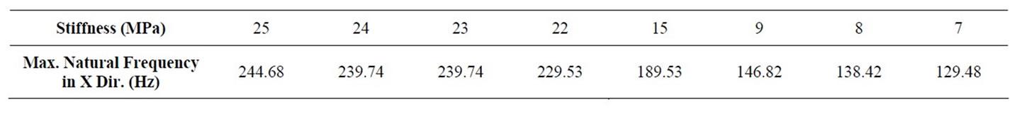
Table 3. Details of natural frequency.
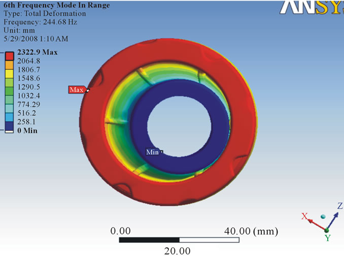
Figure 8. Deformation at stiffness 25 MPa.
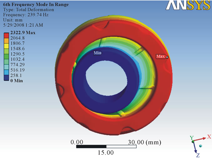
Figure 9. Deformation at stiffness 24 MPa.
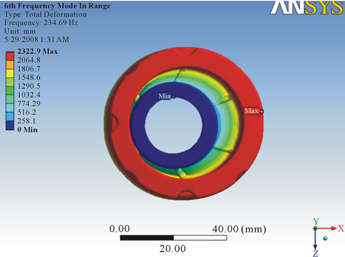
Figure 10. Deformation at stiffness 23 MPa.
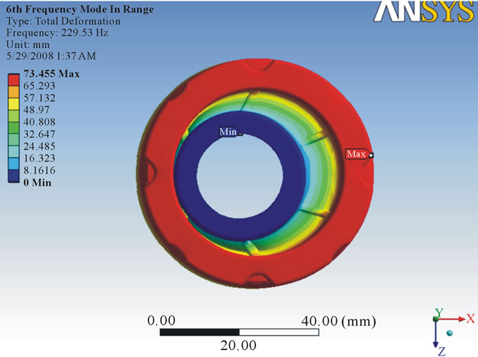
Figure 11. Deformation at stiffness 22 MPa.
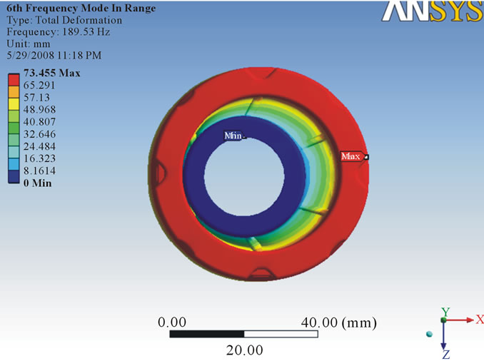
Figure 12. Deformation at stiffness 15 MPa.
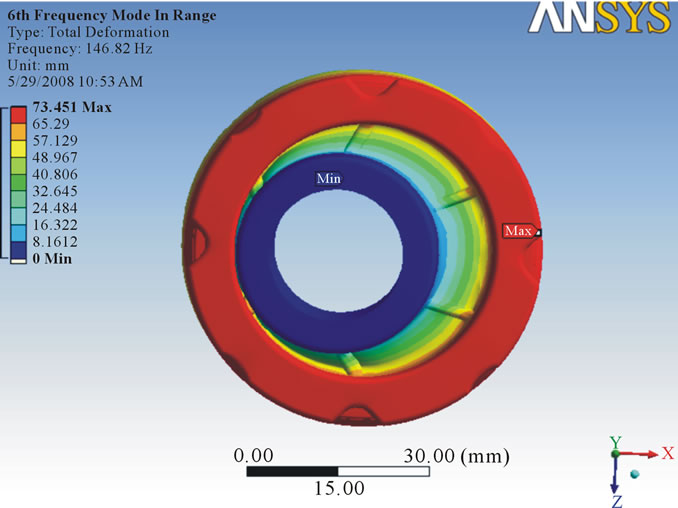
Figure 13. Deformation at stiffness 9 MPa.
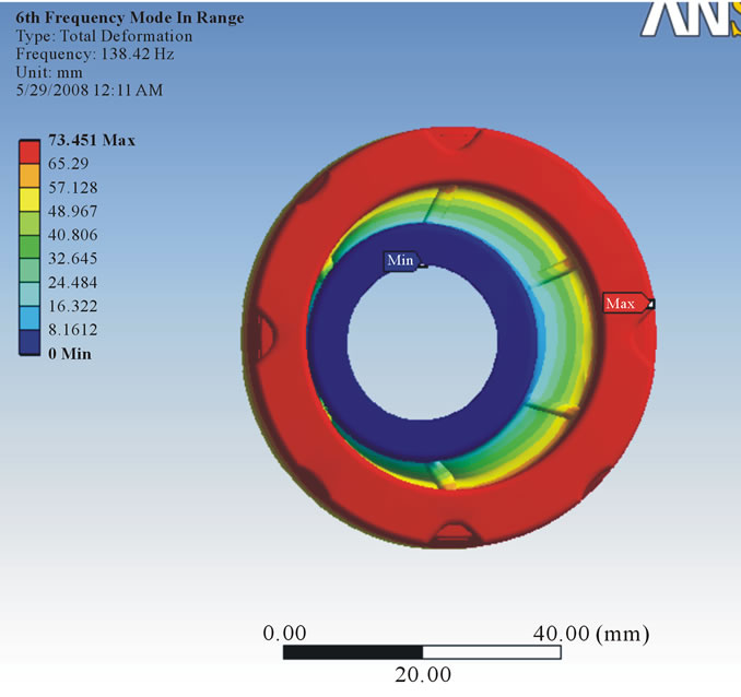
Figure 14. Deformation at stiffness 8 MPa.
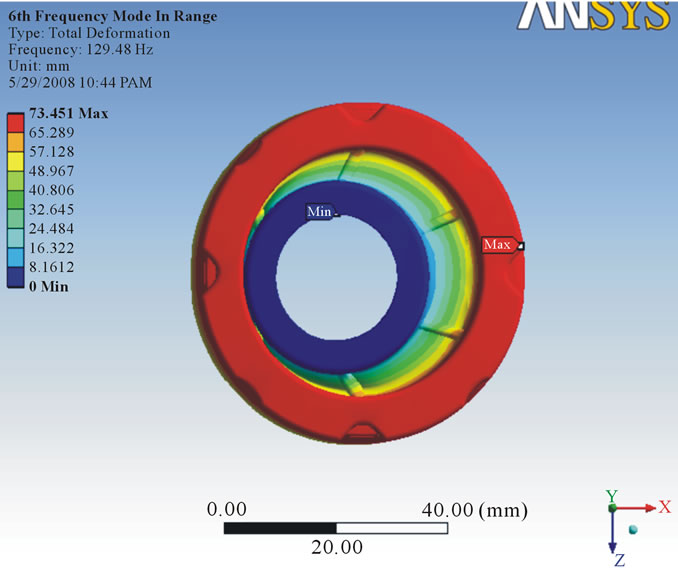
Figure 15. Deformation at stiffness 7 MPa.
analysis. In this analysis, some nonlinearity, such as plasticity will be ignored, even if those are defined. All loads and displacements vary sinusoidal at the same known frequency (although not necessarily in phase). Joints are not allowed in harmonic response analysis. The stiffness as well as damping of springs is taken into account in a Full method of harmonic response analysis. In a Mode Superposition harmonic response analysis, the damping from springs is ignored.
For the damper, boundary conditions are given as cylindrical support and acceleration which is in X direction for Harmonic analysis. So for the damper the maximum frequency in X direction is found out. Following Amplitude Verses Frequency graphs (Figures 16-23) are investigated to get the maximum frequency in X direction for different stiffness.
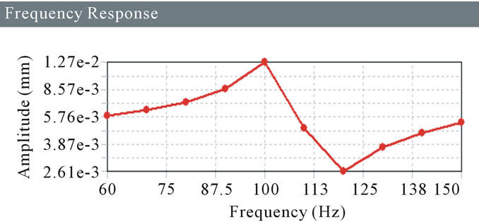
Figure 16. Frequency response for 25 MPa.
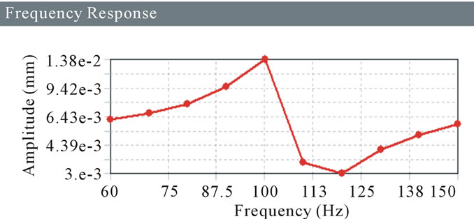
Figure 17. Frequency response for 24 MPa.
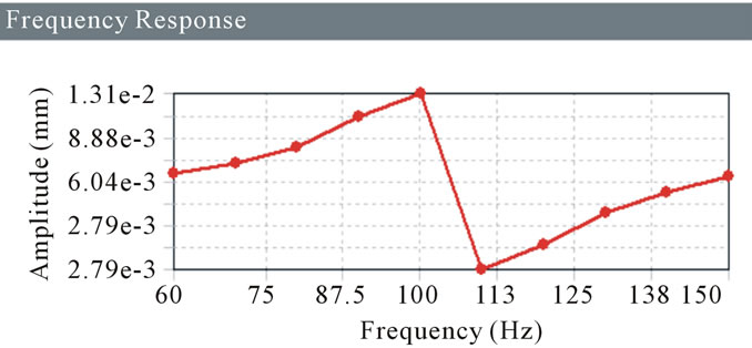
Figure 18. Frequency response for 23 MPa.
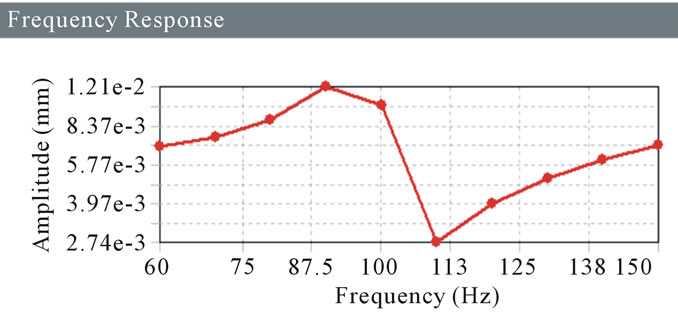
Figure 19. Frequency response for 22 MPa.
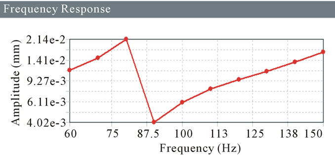
Figure 20. Frequency response for 15 MPa.
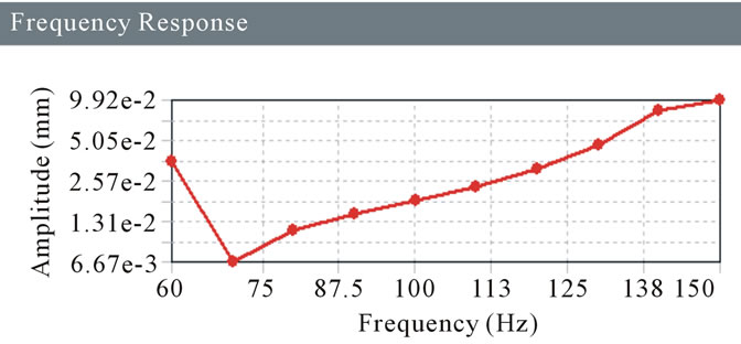
Figure 21. Frequency response for 9 MPa.
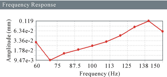
Figure 22. Frequency response for 8 MPa.
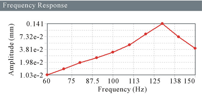
Figure 23. Frequency response for 7 MPa.
5. Conclusion
The Dynamic Damper is attached to one half shaft of CV Joint serves to dampen harmonic vibrations in the drive train and to stabilize the shaft as it spins. It is available in market with stiffness 5 MPa to 25 MPa. From the analysis values, it is concluded that the 8 MPa stiffness is the one which is best suited and resonance criteria satisfied. At 8 MPa the first mode frequency is 58 Hz and maximum natural frequency in X Direction is found as 138 Hz. In Harmonic Analysis the maximum amplitude found at 140 Hz. So the resonance criteria are satisfactory. As the forced frequency range is given as 50 Hz to 150 Hz. Necessary experimental work is performed to validate finding which is out of scope of paper.
REFERENCES
- E. Jack, “Automotive Technology: A System Approach,” 3rd Edition, Thomson Delmar Learning, Clifton Park, 1982, pp. 901-907.
- S. Magirius and D. Booker, “High Speed Constant Velocity Joints, for Car and Light Truck Driveshaft,” SAE Paper 950891, 2005.
- F. Greg and N. Y. Wani, “Finite Element Model Correlation of an Automobile Propshaft with Internal and External Damper,” SAE Paper 2004-01-0862, 2004.
- S. Yu, “Development of Dual Mode Engine Crank Damper,” SAE Paper 2003-01-1675, 2003.
- G. Flesch and O. Zambarda, “The Application of Experiments to a Constant Velocity Plunging Joint Manufacturing Process,” SAE Paper 2003-01-3524, 2003.
- A. Albert and A. Howle, “Design Issues in the Use of Elastomers in Automotive Tuned Mass Dampers,” SAE Paper 2007-01-2198, 2007.
- M. Tetsuji, “Influence of Dynamic Damper Pulley Design on Engine Front Noise,” SAE Paper 2001-01-1419, 2001.