Advances in Chemical Engineering and Science
Vol. 2 No. 2 (2012) , Article ID: 18903 , 9 pages DOI:10.4236/aces.2012.22030
Numerical Study of Oil/Water Separation by Ceramic Membranes in the Presence of Turbulent Flow
1Department of Chemical Engineering, Center of Sciences and Technology, Federal University of Campina Grande (UFCG), Campina Grande, Brazil
2Department of Mechanical Engineering, Center of Sciences and Technology, Federal University of Campina Grande (UFCG), Campina Grande, Brazil
Email: eng.josedite@hotmail.com, fariasn@deq.ufcg.edu.br, gilson@dem.ufcg.edu.br
Received January 17, 2012; revised February 20, 2012; accepted March 29, 2012
Keywords: Ceramic Membranes; Separation; Two-phase flow; Numerical Simulation
ABSTRACT
Disposal of produced water during petroleum extraction causes serious environmental damage, hence the need to complete the water treatment before being disposed to environment within the criteria set established by environmental agencies in the countries. Ceramics membranes have been highlighted as a good device for separating oil/water. These act as a barrier to oil in the aqueous stream, because their essential properties for filtration, such as chemical inertness, biological stability and resistance to high temperatures. The limitation of the separation process is the decay of permeate flux during operation, due to concentration polarization and fouling. In this sense, this paper aims to evaluate numerically the feasibility of the process of separating oil/water by means of ceramic membranes in the presence of a turbulent flow induced by a tangential inlet. The results of the velocity, pressure and volumetric fraction distributions for the simulations different by varying the mass flow rate inlet and different geometric characteristics of the membrane are presented and analyzed.
1. Introduction
Knowledge of the process of separating water-oil is of great importance in the chemical, petrochemical, and food Industries, especially in solving problems related to environmental protection. Based on United States Environment Protection Agency (USEPA) regulations, the daily maximum limit for oil and grease is 42 mg/L and the monthly average limit is 29 mg/L. The Convention for the Protection of the Marine Environment of the North-East Atlantic (OSPAR Convention), the annual average limit for discharge of dispersed oil for produced water into the sea is 40 mg/L [1-4]. Thus, membrane technology has been intensively investigated as an alternative technique for the separation of stable emulsions of hydrocarbons [5], due to essential filtration properties, such as chemical inertness, biological stability and resistance to high temperatures contributing in the process of removing oils in mixtures with water [6].
The membrane separates immiscible solids and solutes that are dissolved, acting as a selective barrier allowing the passage of certain components while preventing the passage of others. In the process of separating two streams are produced: the concentrate stream containing the contaminants initially present in the feed stream and permeated or purified fraction of liquid passing through the membrane.
As reported in [7] ceramic membranes are of great interest in separation processes, due to their higher chemical and thermal stability when compared to polymeric membranes. By using ceramic membranes filtration can occur at temperatures above 500˚C and at pH 1 to 14 and can be cleaned with aggressive chemicals substances, organic solvents or hot water vapor reflux.
Several studies have been reported in the literature using ceramic membranes as device to separate water/oil mixture [8-11] and have shown a separation efficiency ranging between 95% to 99.9% depending on the membrane and of the fluids properties that you want to separate. However, these devices have shown a deficiency with respect to the permeate flow that is reduced over time due to fouling pores.
Given the above, this paper aims to present the numerical study of the behavior of fluids in the process of separating oil/water separation process through ceramic membrane in the presence of a turbulent flow induced by a tangential inlet. For the simulations we used the ANSYS CFX® commercial software (code based on the CFD modeling-Computational Fluid Dynamics) which allows the simulation of systems involving fluid flow, heat transfer and other related physical processes.
2. Problem Description
The study area corresponds to a cylindrical ceramic membrane that acts as a barrier to passage of particles oil droplet through the porous medium. This retention can be fully or partially restricting the carriage of one or more chemical species present in phases depending on the size of the molecules of the involved species. The fluid is injected tangentially in the membrane through a device located in one of its ends and flows along the membrane while the permeated is transported perpendicularly. Representation of the ceramic membrane can be observed in Figure 1, and its dimensions are presented in Table 1.
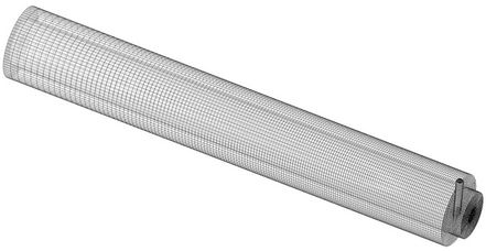
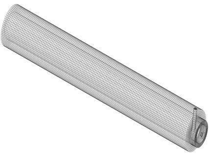
Two membranes configuration were studied: tubular (Figure 2) Grid with 446485 hexahedral elements and annular (Figure 3) grid with 197088 hexahedral elements. The annular space present in Figure 3 is the difference between the two geometries presented in this work.
3. Mathematical Model
Mathematical modeling is a physical representation of reality in the form of a set of consistent equations. The proposed mathematical model to describe the flow in porous media corresponds to a generalization of the equations conservation mass and momentum (NavierStokes) and Darcy’s law applied to the Eulerian-Eulerian
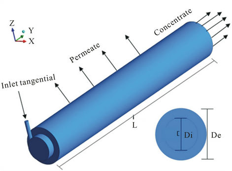
Figure 1. Geometrical representation of the ceramic membrane.
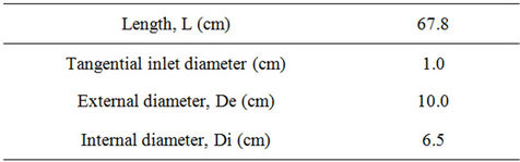
Table 1. Dimensions of the ceramic membrane.
 (a)
(a)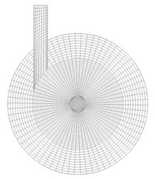 (b)
(b)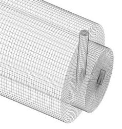 (c)
(c)
Figure 2. Representation of mesh with tubular ceramic membrane.
 (a)
(a) (b)
(b)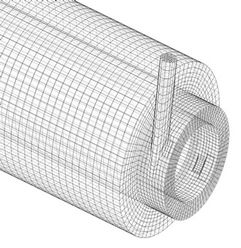 (c)
(c)
Figure 3. Representation of structured mesh with the annular geometry of the ceramic membrane.
model of interfacial transfer and k-ε turbulence model (RNG). The renormalization group (RNG) k-ε model is similar in form to the k-ε model but includes additional terms for turbulence dissipation rate ε, furnishing more accurate predictions of the flow situations, including, separation process, streamlines, curves and stagnant regions, by considering the following simplifications:
1) Newtonian incompressible fluid with constant physical and chemical properties;
2) Stationary and isothermal flow;
3) Mass transfer and interfacial momentum and mass source are neglected;
4) The interfacial forces of non-drag force (forces of lift, wall lubrication, virtual mass, pressure and turbulent dispersion of solid) are neglected;
5) The membrane walls of the tubular and annular geometries are statics.
With these considerations the resulting equations are: given as follows.
3.1. Mass Conservation Equation for the Fluid Phase
The mass conservation is given by (1)
 (1)
(1)
where the Greek sub-indices α represent the involved phases of water/ oil mixture; f, ρ, and  are respectively the volume fraction, density and vector velocity. For phase α, the vector velocity is given by
 .
.
3.2. Equation of Mass Conservation for the Medium Porous
The mass conservation equation for the flow in porous media is defined by the following equation:
 (2)
(2)
where t is the time, f is the volumetric porosity and  is the second order symmetric tensor called the tensor of porosity of the area.
3.3. Momentum Conservation Equation for the Fluids Phases
The linear momentum conservation for multiphase flow is defined by (3):
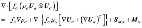 (3)
(3)
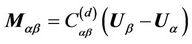
where p is the pressure,  represent the external forces per unit volume of the phase β for phase α.
  describes total force The total force on phase α due to interaction with other phase (
 ) is given by (4):
 (4)
(4)
where,
 (5)
(5)
where  corresponds to the dimensionless drag coefficient given by (7).
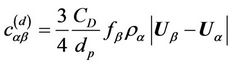 (6)
(6)
where dp is the particle diameter and CD is the drag coefficient. In this work, CD has been adopted to be equal to 0.44 [12] (for the turbulent and viscous regime).
3.4. Momentum Transfer Equation for the Porous Medium
The momentum conservation equation for porous media is defined by the equation (7).
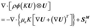 (7)
(7)
where μe is the effective viscosity, and  represents the source of quantity momentum linear, In [8] the source of quantity momentum linear is represented by:
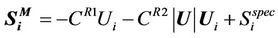 (8)
(8)
where  is the linear resistance coefficient,
  is the quadratic resistance coefficient and
  represents other sources of linear momentum quantity, related to the species present, and U and Ui are superficial velocities.
Therefore, the Darcy’s law generalized becomes:
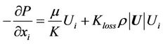 (9)
(9)
where μ denotes dynamic viscosity, Kloss is the empirical coefficient of loss in [12],  and
and  cannot be zero.
Comparing equations (1) and (2) and using actual speeds instead the superficial velocity, the coefficients  and
and  are expressed by:
 (10)
(10)
and
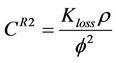 (11)
(11)
3.5. Turbulence Model
Due to complexity of the turbulent fluid flow through the membrane we use k-ε model (RNG) to complete the mathematical formulation. The renormalization group (RNG) k-ε model is similar in form to the k-ε model but includes additional terms for turbulence dissipation rate ε, furnishing more accurate predictions of the flow situations, including, separation process, streamlines, curves and stagnant regions.
The values of turbulent kinetic energy, k, and turbulent dissipation rate, ε are directly obtained from the differential equations of transport as can be observed in (12) and (13):
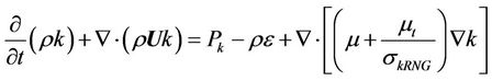 (12)
(12)
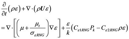 (13)
(13)
where μ is the dynamic viscosity, ρ is the density and μt is the turbulent viscosity which is given by (14).
 (14)
(14)
where Cμ is an empirical constant, and the values of the constants are given by:
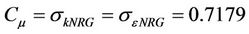 (15)
(15)
and
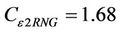 (16)
(16)
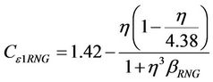 (17)
(17)
where,
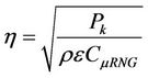 (18)
(18)
In this equation  is the RNG turbulence model constant equal to 0.085 [12],
  is the turbulence production due to viscous and buoyancy forces or shear production of turbulence, which is modeled using (19):
 (19)
(19)
The term Pkb is the production of buoyancy and is modelled by (20) as follows:
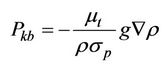 (20)
(20)
where σρ = 1.
The mathematical model does not predict the phenomenon of retention of particles or molecules in a porous medium, but consider difficulty or resistance to passage of the phases (oil and water) in porous media.
3.6. Boundary Conditions and Properties of Fluids and Membrane
To complement the mathematical modeling were defined boundary conditions for the simulated cases (Table 2).
The properties of water, oil and porous media used in this work are shown in Tables 3 and 4.
3.7. Cases Studies
Table 5 summarizes the six studied cases. Were analyzed different simulations varying the inlet velocity as well as some geometric characteristics of the membrane as shown earlier in Figures 2 and 3.
The numerical experiments were performed on a Server Quad-Core Intel Dual Xeon Processor E5430 of 2.66 GHz with 8 GB of RAM available in the laboratories LPFI (Fluid Dynamic Imaging Research Laboratory)
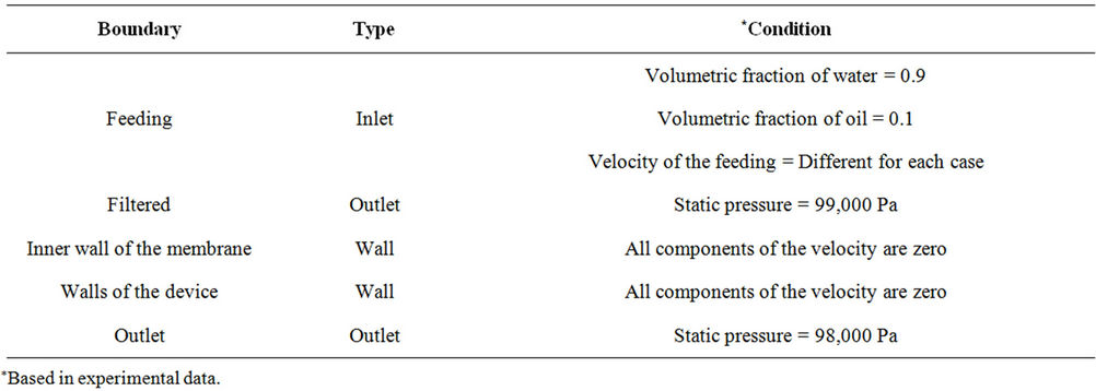
Table 2. Boundary conditions for the studied cases.

Table 3. Physical-chemical properties of fluids.

Table 4. Properties of porous medium used in the simulations.

Table 5. Case studies considering the constant properties.
and LCTF (Thermal and Fluid Computational Laboratory) of Chemical Engineering and Mechanical Engineering Department, respectively, Federal University of Campina Grande, Brazil. The simulation time ranging from 3 to 4 days/simulation.
4. Results and Discussion
The numerical results obtained in research by the meshes presented in Figures 2 and 3 are given by means of streamlines, vector field and volumetric fraction distribution, as well as a graph representing the behavior of the filtered mass flow rate of the water and oil mixture for different inlet conditions of the mixture.
In Figures 4 and 5 are illustrated the behavior of streamlines to the oil and water inside the tubular and annular geometries provided with a ceramic membrane for the different inlet velocities, corresponding to mixture mas flowrate of (1.498; 1.872 and 2.247 kg/s) respectively.
By observing carefully the Figures 4 and 5 we see the presence of two upward streams distinct of fluids in spiral near the tangential inlet that disappears as it departs from the tangential inlet. The decrease of the spiral motion is related to the reduction of angular momentum and
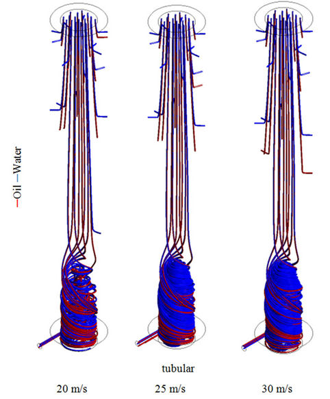
Figure 4. Streamlines in the tubular geometry, for differents inlet mixture velocity.
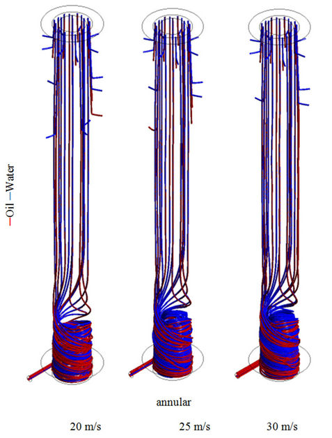
Figure 5. Streamlines in the annular geometry, for differents inlet mixture velocity.
the axial momentum to dominate the flow along the geometry. This behavior leads to the appearance of more orderly flow leading to the velocity profile close to parabolic (see vector field in Figure 6) observed in flow in tubes in laminar regime. On the other hand, the difference in the behavior of the currents of water and oil is attributed to density difference between the phases and the balance of drag, centrifugal and weight forces throughout the apparatus.
By observing Figure 7, where is represented a detail in the region near the tangential inlet for the two geometries analyzed (tubular and annular), one sees clearly the influence of the geometric aspect in the behavior of water and oil streamlines. The fact of insertion of a tube in the tubular device, forming an annular space, eliminates the region of mixing near the axial of the membrane.
 (a)
(a)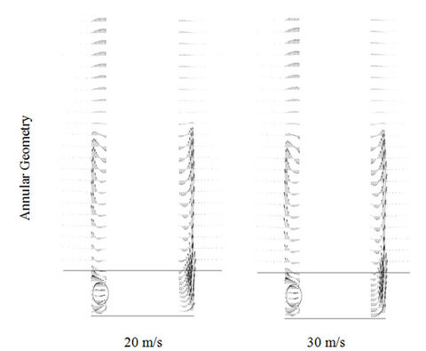 (b)
(b)
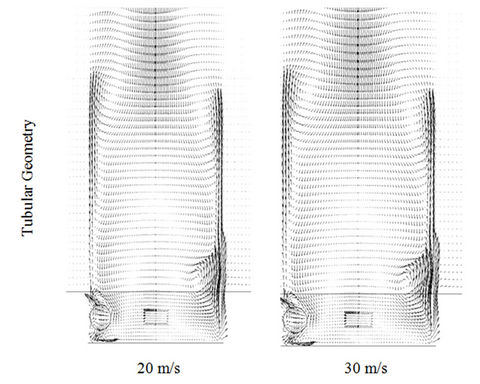
Figure 6. Details of the mixture velocty vector in (a) tubular and (b) annular geometries for different inlet mixture velocity.

Figure 7. Details of the streamlines in (a) tubular and (b) annular geometries for different inlet mixture velocity.
This behavior is provided by reducing the pressure at the center of the tubular geometry (Figure 8). The results of the vector field of velocity shown in Figure 6. These results allows us to observe that the swirling motions (or recirculation zones) are more important, i.e., presents larger dimensions intensities, in tubular than in the annular geometry. This leads to a probable mixture of the water with the oil providing a greater dispersion of oil and the possible formation of emulsion between the phases.
Observing the behavior of the velocity vector field in the annular geometry it is clear that the length of the recirculation zones are smaller than those observed in the tubular geometry which provides a decrease in the swirling flow along the membrane starting from tangential inlet, from this position the axial momentum becomes dominant instead of the angular momentum.
Returning to Figure 8, where is represented the pressure distribution upon three plans around the tangential inlet, it is observed that the largest gradients are located in the porous medium, which ensures the permeation of fluid in the membrane in the radial direction thus providing the emergence of the filtrate. By observing carefully, one realizes that these gradients are most important to the annular geometry than for the tubular, which indicates a greater amount of filtrate volumetric and consequently a greater amount of oil present in the filtrated. This situation can be verified by observing the xy plane for the two geometries in Figure 9, which depicts the volumetric fractions distributions of oil on these plans. It
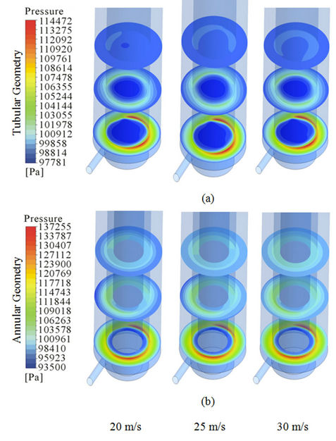
Figure 8. Representation of the pressure distribution on the xz planes for tubular and annular geometries for the differents inlet velocity.
is clearly shown that the annular geometry has more permeation of the oil into the membrane. This phenomenon is possibly a problem for the membrane because there may be an obstruction or greater drag of oil by water across the membrane.
The Figures 10 and 11 are represented the filtered water and oil mass flow rate as a function of mixture mass flow rate in the feed for tubular and annular geometries. These figures show that there is an increase of filtered water mass flow rate as well for oil, for the annular geometry compared to the tubular geometry. While there has been an increase in oil concentration in the filtrate using the annular geometry, it is clear that there is a very significant increase in the amount of filtered water.
It should be noted that even with the low increase in oil concentration in the filtrate using the annular geometry, there was an increase in the production of treated water compared to the tubular geometry. This high concentration of oil may be related to the permeability adopted in this work, so if it reduced the value of permeability probably will reduce the oil concentration in the filtrate.
5. Conclusions
From the numerical results of the oil/water separation
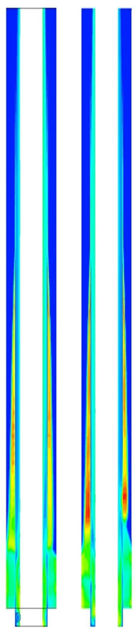
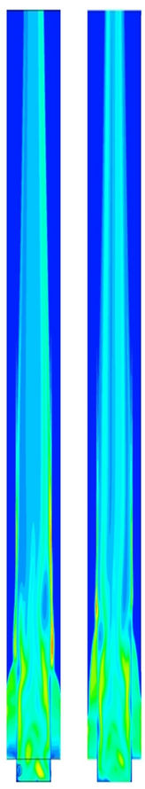

Figure 9. Volumetric fraction distribution on the xy plane for the tubular and annular geometries for the inlet mixturevelocity equal to 20 m/s.
process using membrane with tubular and annular geometries, under the evaluated conditions, we can be concluded that:
• The proposed mathematical model was able to predict the fluid-dynamics for the separation process of water and oil mixture by ceramic membrane;
• It was possible to observe a three-dimensional behavior of the flow within the two geometries evaluated;
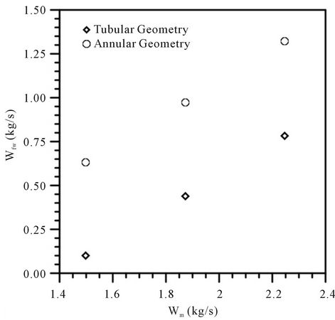
Figure 10. Filtrate water mass flow rate as a function of the inlet mixture mass flow rate for tubular and annular geometries.
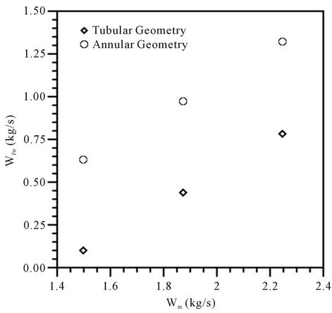
Figure 11. Filtrate oil mass flow rate as a function of the inlet mixture mass flow rate for tubular and annular geometries.
• The fluid-dynamic behavior inside the geometries showed a decrease in turbulence intensity of fluids starting from the tangential inlet of the membrane;
• The increase in feed streams provided an increase in the filtered water and oil mass flow rate for the annular and tubular geometries
• The annular geometry presented higher values of filtrate for both the oil to water as compared to the tubular geometry. However, it requires a further examination of the parameters of the porous medium, such as permeability, to minimize the presence of oil in the filtrate.
6. Acknowledgements
The authors would like to express their thanks to CNPQ, CAPES, FINEP and ANP. (Brazil), for supporting this work, and are also grateful to the authors cited in the text that helped in the improvement of quality.
REFERENCES
- J. M. Neff, “Bioaccumulation in Marine Organisms: Effect of Contaminants from Oilwell Produced Water,” Elsevier, Netherlands, 2002.
- http://www.epa.gov
- OSPAR Commission, “Report on Discharges Spills and Emissions from Offshore Oil and Gas Installations,” 2005. http://www.ospar.org/documents/dbase/publications/p00221 Offshore%20report%202003.pdf
- F.-R. Ahmadun, et al., “Review of Technologies for Oil and Gas Produced Water Treatment,” Journal of Hazardous Materials, Vol. 170, No. 2-3, 2009, pp. 530-551. doi:10.1016/j.jhazmat.2009.05.044
- M. A. A. Zaini, R. G. Holdich and I. W. Cumming, “Crossflow Microfiltration of Oil in Water Emulsion via Tubular Filters: Evaluation by Mathematical Models on Droplet Deformation and Filtration,” Jurnal Teknologi, Vol. 53, 2010, pp. 19-28.
- S. R. H. Abadi, M. R. Sebzari, M. Hemati, F. Rekabdar and T. Mohammadi, “Ceramic Membrane Performance in Microfiltration of Oily Wastewater,” Desalination, Vol. 265, No. 1-3, 2011, pp. 222-228. doi:10.1016/j.desal.2010.07.055
- S. Benfer, U. Popp, H. Richter, C. Siewert and G. Tomandl, “Development and Characterization of Nano-filtration Membranes,” Separation and Purification Technology, Vol. 22-23, 2001, pp. 231-237. doi:10.1016/S1383-5866(00)00133-7
- S. Ahmed, M. T. Seraji, J. Jahedi and M. A. Hashib, “CFD Simulation of Turbulence Promoters in a Tubular Membrane Channel,” Desalination, Vol. 276, No. 1-3, 2011, pp. 191-198. doi:10.1016/j.desal.2011.03.045
- S. R. Lautenschlager, S. S. F. Filho and O. Pereira, “Mathematical Modeling and Operational Optimization of Ultrafiltration Membrane Processes,” Engenharia Sanitária Ambiental, Vol. 14, 2009, pp. 215-222. doi:10.1590/S1413-41522009000200009
- D. F. Maia, “Development of Ceramic Membranes for Oil/Water Separation,” Ph.D. Thesis, Federal University of Campina Grande, Campina Grande, 2006.
- R. Del. Colle, R. N. Haneda, E. Longo, M. J. Godinho and S. R. Fontes, “Method of Chemical Impregnation Applied to Microporous Tubes and Tubular Membranes for the Microfiltration of Emulsions and Suspensions of Bacteria,” Cerâmica, Vol. 54, 2008, pp. 21-28.
- ANSYS CFX, “User Manual Theory,” ANSYS CFX-Solver Theory Guide, ANSYS Inc., Canosburg, 2009.
- A. L. Cunha, S. R. F. Neto and H. L. Lira, “Application of Fluid Dynamic Computational Oil/Water Separation in through Selective Membranes,” Proceedings of the 3rd Congress of Scientific Initiation of the Federal University Campina Grande, Campina Grande, 2006, pp. 1-11.