International Journal of Modern Nonlinear Theory and Application
Vol.1 No.3(2012), Article ID:23097,6 pages DOI:10.4236/ijmnta.2012.13016
Voltage Control of a 12/8 Pole Switched Reluctance Generator Using Fuzzy Logic
1Fars Regional Electric Company, Shiraz, Iran
2Pasargad Higher Education Institute, Shiraz, Iran
3Shiraz University, Shiraz, Iran
Email: faridnia@frec.co.ir, ma.seyedyazdi@gmail.com, shabani@ecs.csus.edu
Received June 8, 2012; revised July 5, 2012; accepted August 8, 2012
Keywords: Wind Energy; Switched Reluctance Generator; Voltage Control; Fuzzy Logic Control
ABSTRACT
This paper presents a voltage controller for a 12/8 switched reluctance generator (SRG). SR machines have a robust with simple structure because they have no windings or permanent magnets on the rotor, so they are capable of working at high speed application and at rough condition. However, due to nonlinear nature, doubly salient poles, time variant parameters, and non-ideal current waveform, The SRG output voltage inherently contains ripples. The proposed voltage controller is based on fuzzy logic that is very efficient over uncertainty and parameter variations. The effectiveness of the proposed control method is verified by comparing the obtained result with that of a PI-controller.
1. Introduction
Nowadays electricity demands is increasing highly, so the use of small power plants whose design and construction are less time consuming is very essential. One of the small power plants is a wind power plant that in addition to being less time consuming in construction, it has many other advantages. Due to their small size, small wind turbines have the advantages of easy transportation from manufactory to power plant, easy installation in every where e.g. near any load center, and easy operation in high speed wind. Small wind turbines using high reliable generators are the best candidates for working in stand-alone application either in remote areas or in urban areas [1].
Among several kinds of generators used as wind generators, switched reluctance generator (SRG) is one of the best candidates for this application. The SRG has robust with simple structure due to the fact that it has no windings or permanent magnets on the rotor. Therefore it is capable of working at high speed application and at rough condition. The main advantages of the SRG are high efficiency, simple topology, the requirement of no starting torque and robustness. SRG is inherently a variable speed machine. The variable speed operation in wind generation leads to the extraction of extra energy from the wind stream and the decrease of the mechanical stresses within the system [2].
Recently, many studies have been done on SRG in various applications such as wind generation. Many papers have been presented and examined different types of drive circuits for SRG in various applications [3,4]. In [3] the application of the switched reluctance generator in direct drive wind turbine was discussed. In [4] a new structure is presented for variable speed wind SRG. In [5] switched reluctance machine was considered as subsidiary wind power generation in the grid connection. The procured results have demonstrated that the SRG in terms of constant speed is stable and at variable speed condition works well. On the other hand, some studies have been made on controlling of SRG’s output signals for wind generation application in order to reduce its drawbacks [6]. However, offered control methods are not complete and comprehensive, and numerous challenges are ahead of these methods Because of nonlinear nature, doubly salient poles, Time variant parameters, and non-ideal current waveform, the SRG output voltage inherently contains ripples. In [7], a closed loop control of output power of a SRG driven by a variable speed wind turbine is presented. The pulse width modulation control method is adopted for control the phase current of the SRG in medium and low speed range. The paper uses the single pulse mode control method for control the SRG’s output power in high speeds. In [8], to reduce the output voltage ripples of SRG, a PI-configured DC-link filter is presented. In order to lessen the effects of parameters uncertainty in switched reluctance generation systems, some studies are done on the use of fuzzy control method to determine the conducting angles. In [9], a variable speed SRG is introduced and the turn-on angle control strategy is presented. In this paper a fuzzy logic algorithm for maintaining output power is explained, and the variation of the DC output voltage and current are the two inputs and the turn-on angle is the output control parameters.
This paper considers a switched reluctance generator driven by a wind turbine in Figure 1, and presents a fuzzy logic based controller for smoothing the SRG output voltage fluctuations. The obtained results from fuzzy controller are compared with the results obtained from a PI controller.
The organization of this paper is as follow. Section 2 presents a summary about SRG theory and its mathematical model. Section 3 describes the proposed fuzzy logic control method and the related rules and membership functions are considered in Section 4. The simulation results are shown and discussed in Section 5. Section 6 presents the conclusions.
2. A Brief Review on SRG Theory and Voltage Control
SR machines have very simple structure that lead to the advantages of these machines. In these machines, the 3-phase windings are placed on stator poles and there is no winding or magnet on rotor poles. The stator windings serve both the roles of armature windings and excitation windings in different times. Both stator and rotor has salient-pole structure. This doubly salient structure offers higher speed operation and higher efficiency. Lack of windings on the rotor is the cause of no electric losses in rotor, small moment of inertia, fast response, low manufacturing cost and high reliability. Figure 2 shows the basic configuration of the 12/8 pole-three phase SR machine that used in this paper. Anyway the SR generator has few disadvantages such as complicated power electronic drive circuit, acoustic noise and output voltage ripple. Fortunately by the use of advanced drive method and advanced control method these drawbacks can be removed.
In SR machine, energy conversion is based on inductance variation due to pole saliency of stator and rotor. In SR generator, the tendency of rotor to resist changing the position where the inductance of excited phase is maximized produces energy. In generating mode of SR ma-
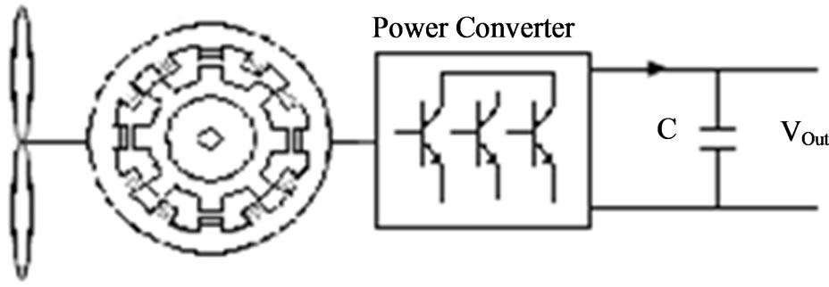
Figure 1. SRG wind turbine system [4].
chine, when a rotor pole is aligned with a stator pole, the phase related to that stator pole will turn on to resist moving rotor. This action causes that the energy is saved in magnetic field and electrical power is produced. Therefore it is essential for this machine to have a driving system that can identify the rotor position and can switch on or off the proper phase in accordance with rotor position. Figure 3 shows the relation between one-phase inductance profile of SR machine and rotor position angle θ. As understand from Figure 3, to use SR machine as a generator the phases should be turned on at the negative slope of the phase inductance profile i.e.
when 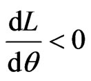 .
.
This point can be confirmed referring to SR machine’s torque formula in (1).
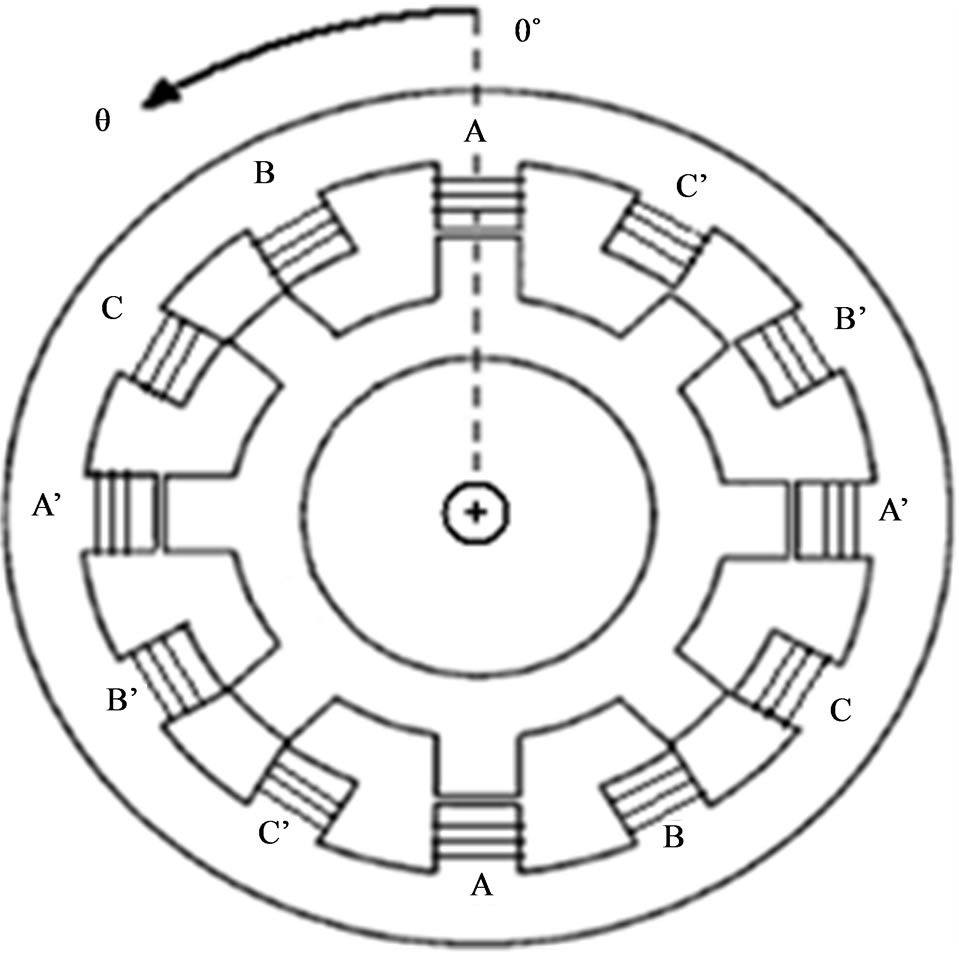
Figure 2. Configuration of a three phases 12/8 pole SR machine.
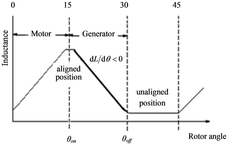
Figure 3. Idealized phase inductance versus rotor position curve.
 (1)
(1)
The equation indicates that in the region of 
the torque is negative, so using the machine in this region is compatible with generator operation. As previously mentioned, SR machine needs a driver that recognizes rotor position and then switches proper phase on or off corresponding to the rotor position. In this paper a three-phase asymmetric bridge converter shown in Figure 4 is used as the drive system for SR generator.
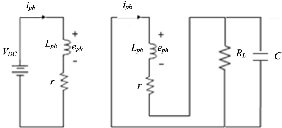
The inductances La, Lb and Lc illustrate the inductance of phase A, B and C, respectively and resistor r shows winding resistance of each phase. In Figure 4, the two transistors per phase turn on and off simultaneously. In a SR generator at each moment, there is only one phase that is on. Therefore at each moment there is only one phase that is connected to DC power supply. As explained in our previous work [4], Figure 5(a) shows an equivalent circuit of one phase of SR generator when the switches of this phase are turned on and then the DC power supply excites the windings of the phase. Equations (2)-(5) describe the dynamics of one phase of SR generator for Figure 5(a).
 (2)
(2)
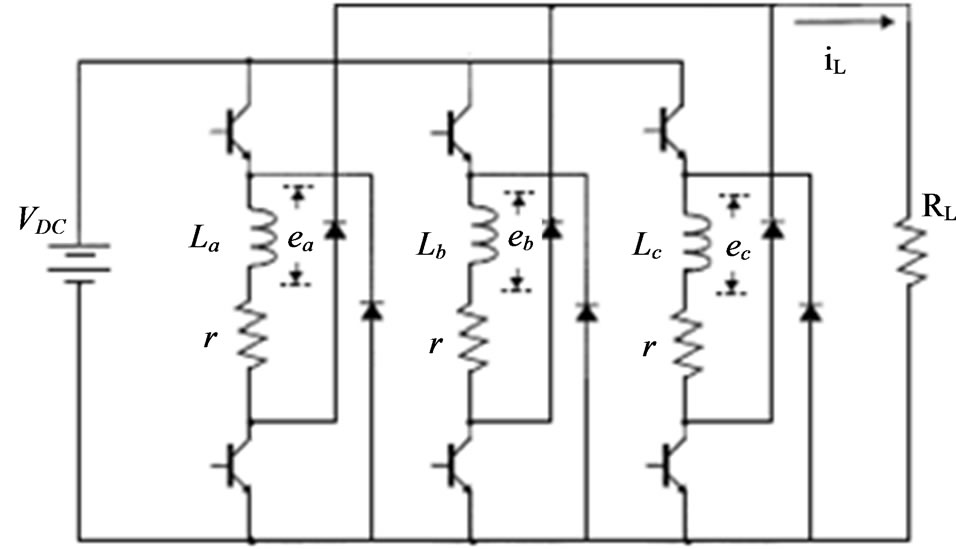
Figure 4. Basic schematic of three phase converter for switched reluctance generator.
 (a) (b)
Figure 5. Operation modes of the phases of SRG. (a) Exciting mode; (b) Generating mode.
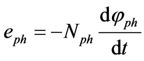
where eph is the voltage across the phase and iph is the current that flows through the phase.
 (3)
(3)
where φph is the phase flux and Nph is the number of windings of the phase. Because φph = Lph·iph,
 (4)
(4)
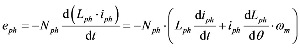
Substituting (4) in (2)
 (5)
(5)
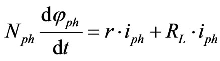
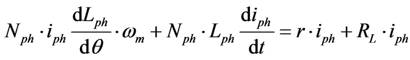
where 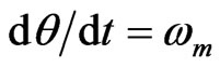 and ωm is the rotational speed of rotor. Equation (5) is the basic voltage of one phase if the phase is turning on. The first term on the right hand of (5) is the back EMF that the generated electrical power is proportional to this term. Figure 5(b) shows an equivalent circuit of the same phase of SRG when the switches are turned off. In this case the inductance current that can not be zero immediately flows through freewheeling diodes and supplies resistance load. Equations (6)-(8) describe the dynamics of the phase of SRG for Figure 5(b).
 (6)
(6)
Substituting eph from (3) into (6),
 (7)
(7)
Substituting φph from (4) into (7),
 (8)
(8)
3. Fuzzy Logic Control
During the past decade, fuzzy logic control has emerged as one of the most active and fruitful research areas in the application of fuzzy set theory, fuzzy logic and fuzzy reasoning. In contrast to conventional control techniques, fuzzy logic control is efficiently utilized in complex ill-defined processes that can be controlled by a skilled human operator without much knowledge of their underlying dynamics. The basic idea behind fuzzy logic control is to incorporate the “expert experience” of a human operator in the design of a controller in controlling a process whose input-output relationship is described by a collection of fuzzy control rules (e.g. IF-THEN rules) involving linguistic variables. Also fuzzy logic controller provides the best answers in system outputs with uncertainties. In this paper fuzzy approach is used to get a good performance of SRG output voltage.
For fixing the generator terminal voltage, it is necessary to find a suitable controller keeping voltage in dc mode. Fuzzy logic based on linguistic rules has been chosen in this paper. Two input and one output variables are selected for fuzzy logic controller. First Input variable is voltage error (ε) and the second input variable is voltage error difference in two consecutive intervals (Δε). The definition of ε and Δε can be expressed mathematically as (9) and (10). The output variable is the amount of variation in conducting angle (θd) that is needed to earn an output voltage with minimum of deviation. The ranges of the first input, the second input, and the output vary from –43 to 43, –3.5 to 3.5 and –3 to 3 respectively. The variation of Δε is practically low.
 (9)
(9)
 (10)
(10)
4. Fuzzy Set Membership and Control Rules
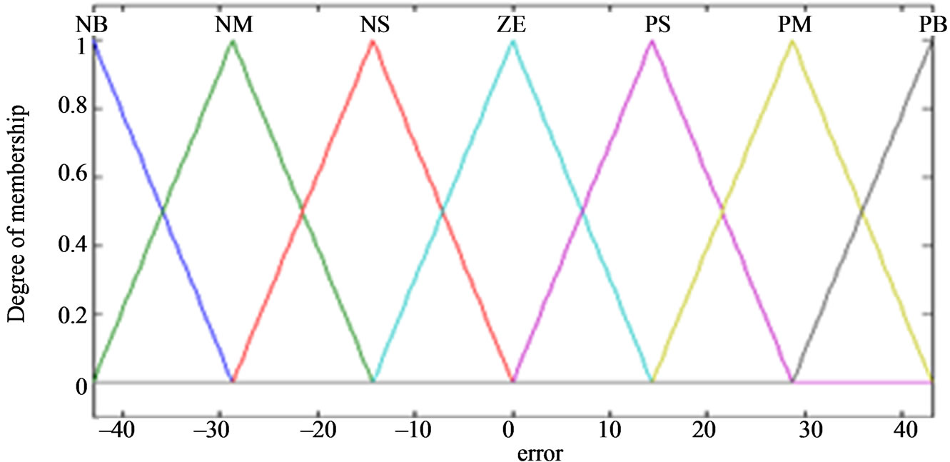
The fuzzy sets considered for the inputs and the output are similarly in seven ranks: {NB (Negative Big), NM (Negative Medium), NS (Negative Small), ZE (Zero), PS (Positive Small), PM (Positive Medium) and PB (Positive Big)}. Mentioned membership functions are shown in Figure 6. As it is known from SRG theory, in order to maintain Vc at the desire level (equal to Vref), if “Vc – Vref” is negative then θd has to be increased, and also if “Vc – Vref” is positive then θd has to be decreased adequately. The rules shown in Table 1 are considered to damp the overshoot of the output voltage. It is obvious that these few rules are utilized to omit the SRG terminal voltage overshoot. Figure 7 shows three dimensional relationships between two inputs and the output of the fuzzy sets used in this paper.
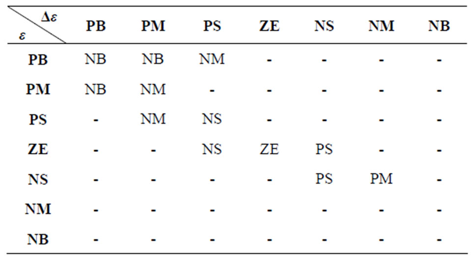
Table 1. Fuzzy logic rules considering two inputs and one output.
 (a)
(a)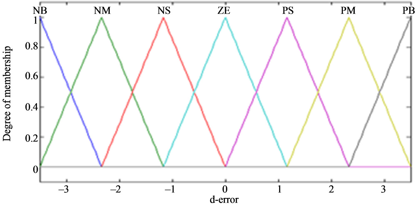 (b)
(b) (c)
(c)
Figure 6. (a) Membership function of ε; (b) Membership function of Δε; (c) Membership functions of θd.
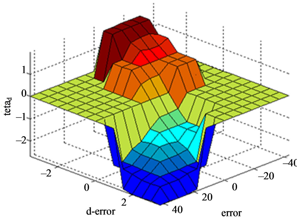
Figure 7. 3-D relationships between two inputs and the output of the fuzzy control rules.
5. Simulation Results
According to mentioned material on last section, this paper proposed a fuzzy logic based voltage controller for a 12/8 SRG driven by a wind turbine. The parameters of the simulated SRG were shown in Table 2. Output voltage waveform of applied SRG without any controller was shown in Figure 8. In this case, the capacitor paralleled with the external load is the only used means to smooth the output voltage. However the waveform has an undesirable overshoot about 19% of Vref. Two kinds of controllers are used to reduce the voltage overshoot and then smooth output voltage. First, a PI controller is applied to the SRG system. Figure 9 shows the effects of the PI controller on the output voltage. As shown in this figure, this controller could omit the overshoot completely. However, the required gain for PI controller is too high (k = 1000), and consequently so expensive. Furthermore, the higher gain in PI controller, the more instability in system. In addition, this controller results in
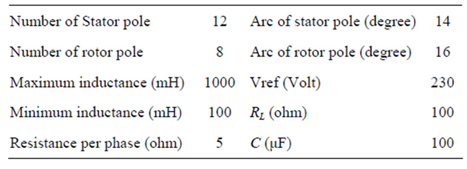
Table 2. SRG control system parameters.
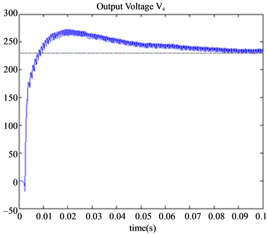
Figure 8. SRG output voltage waveform without any controller.
an increase in settle time of the SRG output voltage whereas deduction in settle time is desirable. Second, the fuzzy logic based controller is applied to the SRG system that its output voltage simulation is shown in Figure 10. The result shows this controller is so helpful to dampen the voltage overshoot quickly and it is more stable than PI controller. In this case, the voltage is fluctuating between 223 and 237 volt and the maximum of output
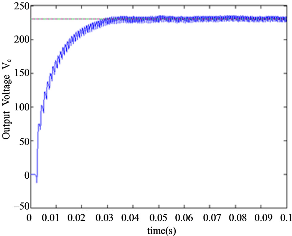
Figure 9. SRG output voltage waveform with PI controller.

Figure 10. SRG output voltage waveform with fuzzy logic controller.
voltage is 243 volt.
6. Conclusion
Due to the absence of windings or permanent magnets on the rotor, switched reluctance machines have a robust with simple structure. Therefore they afford to work at high speed applications and at rough conditions. However, due to numerous nonlinearities, The SRG output voltage innately contains significantly ripples. In this paper a 12/8 SRG is firstly considered and the mathematical model of its output voltage is extracted. Then, a Fuzzy logic based controller is presented to smooth the output voltage. The fuzzy controller receives the reference voltage and the output voltage of the SRG as its inputs, and returns the conducting angle as its output. The effect of mentioned controller on the output voltage is compared with that of a PI-controller. The result shows that in the presence of significant nonlinearity and uncertainty, fuzzy logic controller is more rapid and more stable than the PI controller. Therefore the results verify the effectiveness of the fuzzy logic based controller over the output voltage of a switched reluctance generator.
REFERENCES
- R. Pena, R. Cardenas, G. M. Asher and J. C. Clare, “Vector Controlled Induction Machines for Stand-Alone Wind Energy Applications,” Conference of Record of the IEEE Industry Applications Conference, Rome, 8-12 October 2000, Vol. 3, pp. 1409-1415.
- D. A. Torrey, “Switched Reluctance Generators and Their Control,” IEEE Transactions on Industrial Electronics, Vol. 49, No. 1, 2002, pp. 3-14. doi:10.1109/41.982243
- M. A. Mueller, “Design and Performance of a 20 kW, 100 rpm, Switched Reluctance Generator for a Direct Drive Wind Energy Converter,” IEEE International Conference on Electric Machines and Drives, San Antonio, 15 May 2005, pp. 56-63.
- H. Kazemi Kargar, M. Yazdi and A. Siadatan, “New Structure for High Speed and Variable Speed Wind Turbine Based Switched Reluctance Generator,” IEEE International Conference on Power and Energy, Kuala Lumpur, 29 November-1 December 2010, pp. 200-205. doi:10.1109/PECON.2010.5697594
- A. Fleury, D. A. de Andrade, F. dos Santos e Silva and J. L. Domingos, “Switched Reluctance Generator for Complementary Wind Power Generation in Grid Connection,” IEEE International Electric Machines & Drives Conference, Antalya, 3-5 May 2007, Vol. 1, pp. 465-470.
- A. Takahashi, H. Goto, K. Nakamura, T. Watanabe and O. Ichinokura, “Characteristics of 8/6 Switched Reluctance Generator Excited by Suppression Resistor Converter,” IEEE Transactions on Magnetics, Vol. 42, No. 10, 2006, pp. 3458-3460.
- R. Cardenas, R. Pena, M. Perez, J. Clare, G. Asher and P. Wheeler, “Control of a Switched Reluctance Generator for Variable-Speed Wind Energy Application,” IEEE Transactions on Energy Conversion, Vol. 20, No. 4, 2005, pp. 781-791. doi:10.1109/TEC.2005.853733
- D. B. Wicklund and D. S. Zinger, “Voltage Feedback Signal Conditioning in Switched Reluctance Generation Systems,” IEEE Applied Power Electronics Conference and Exposition, New Orleans, 6-10 February 2000, pp. 376-380.
- H. Chen and Z. Shao, “Turn-On Angle Control for Switched Reluctance Wind Power Generator System,” 30th Annual Conference of IEEE Industrial Electronics Society, Busan, 2-6 November 2004, pp. 2367-2370.