Open Journal of Civil Engineering
Vol. 3 No. 3 (2013) , Article ID: 36395 , 6 pages DOI:10.4236/ojce.2013.33023
A New Method for Predicting the UL of Circular CFST Columns
College of Civil Engineering, Fuzhou University, Fuzhou, China
Email: *xinmengyu@gmail.com, baochunchen@fzu.edu.cn
Copyright © 2013 Xinmeng Yu, Baochun Chen. This is an open access article distributed under the Creative Commons Attribution License, which permits unrestricted use, distribution, and reproduction in any medium, provided the original work is properly cited.
Received April 27, 2013; revised May 27, 2013; accepted June 5, 2013
Keywords: Concrete Filled Steel Tube Column; Ultimate Load Capacity; Simplified Method; Reduction Factor
ABSTRACT
Concrete filled steel tube structures have gained booming development in recent decades, especially in China. Simplified methods have been proposed in design codes, such as the Eurocode 4 (EC4) and the China engineering and construction specification (CECS). In EC4, the confinement effect is reasonably related to slenderness and load eccentricity. The CECS method is much straight forward in that the slenderness ratio and load eccentricity are treated as independent reduction factors. To make use of the advantages of both the CECS and the EC4 methods, the CECS method is modified to consider the confinement effect associated with slenderness and load eccentricity. It is shown that the proposed method can predict well the ultimate load capacity of circular section concrete filled steel tube columns.
1. Introduction
Concrete filled steel tube (CFST) columns have been widely used in high rise buildings and bridges. Previous researches have shown that the mutual strengthening mechanism of the steel tube and the concrete core helps to gain higher load capacity, especially in circular CFST columns. This mechanism has attracted significant research efforts on the development of simplified methods to predict the ultimate load capacity (UL) of CFST columns. The outcomes have been incorporated into design codes, such as EC4 [1], LRFD [2], AIJ [3], CECS [4], DL/T [5] and so on.
The philosophy behind these methods may be different; however, the accuracy of them is reasonable in that they are more or less based on statistical analysis on available test data. No doubt, this is a right way in scientific research and application.
However, since each method has its own material properties and methodology, the equivalency behind them seems vague. It is meaningful to develop a new method which makes the best of the pros but cons of the methods. This research aims to derive a new UL prediction method based on CECS and EC4 crosswise.
2. Simplified UL Prediction Methods in CECS and EC4
In CECS, the UL of a CFST column is calculated by
 (1)
(1)
where  is the cross section resistance derived from limit equilibrium state [6];
  and
and  are independent reduction factors considering stability and load eccentricity, respectively, obtained from regressive analysis on test data.
 (2)
(2)
 (3)
(3)
 (4)
(4)
Note that there is no eccentricity limit in Equation (4).
In EC4, the UL of a CFST column is calculated by
 (5)
(5)
where  is the cross section resistance considering the influence of confinement effect, which is related to load eccentricity and slenderness.
 (6)
(6)
where  and
and  are the steel strength reduction factor and concrete strength enhancement factor (due to confinement effect), respectively, when
  and
and ;
;  is the relative slenderness of the CFST column. Otherwise, the strengthening effect is neglected.
 (7)
(7)
 (8)
(8)
 is analogues to the column buckling resistance reduction factor derived theoretically from a steel column with initial out-of-straightness deflection at mid-height with a little modification [7].
 (7)
(7)
where ![]() is a parameter depending on internal reinforcing bars. When the axial reinforcing ratio is no greater than 3%,
is a parameter depending on internal reinforcing bars. When the axial reinforcing ratio is no greater than 3%,
 (8)
(8)
Apparently, the EC4 approach is different from CECS in that the load eccentricity is no longer an independent parameter, neither is the slenderness effect. Therefore, the philosophy behind CECS and EC4 is different. In addition, the stress-strain relationships of confined concrete are different.
In CECS, a nonlinear restrained concrete property is employed.
 (9)
(9)
In EC4, the restraining effect can be expressed in the following form as prescribed in EC2 [8].
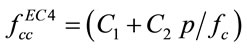 (10)
(10)
where C1 and C2 depends on the lateral confinement pressure, p. That is
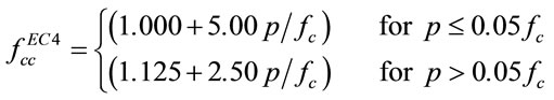 (11)
(11)
From the illustration above, it is clear that the CECS method is much simpler. However, the effects of load eccentricity and slenderness on the strength of concrete are not clear in CECS. This triggers the motive of this research to develop a method which absorbs the merits of these two methods: inheriting the simple framework of the CECS method, but explicitly enriching the reduction factors with the confinement characteristics prescribed in the EC4.
3. Development of a Simplified Method for UL Prediction of Circular CFST Columns
3.1. The Cross Section Resistance of CFST Columns
In limit equilibrium state, the steel tube reaches its ultimate strength, i.e., gets yielded. From Equation (10), it is known that the concrete strength is a function of lateral pressure governed by the state of the steel tube. The UL of the CFST column section is the maximum combination of the stresses in steel and concrete. It is assumed here that the stress distributions on the concrete section and the steel section are both uniform.
The stress distribution in a thin wall steel tube can be reasonably assumed to be planar. When the tube gets yielded, according to the Von Mises yield criterion, we have
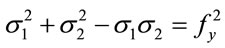 (12)
(12)
where  and
and are principal stresses in axial and lateral directions;
  is the yield strength of tube steel. Note
 , where
  is the axial compressive stress.
It can be derived that
 (13)
(13)
 (14)
(14)
Substituting Equations (13) and (14) into Equation (12) and rearranging, we have
 (15)
(15)
Therefore, at ultimate limit states, the load resistance of the cross section can be expressed as
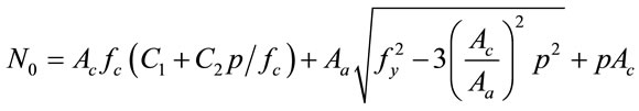 (16)
(16)
The maximum value of N0 requires
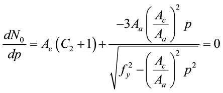 (17)
(17)
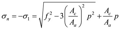
Therefore, at ultimate limit states, the lateral pressure on the concrete core is
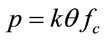 (18)
(18)
where  is the confinement effect factor,
 , and
, and
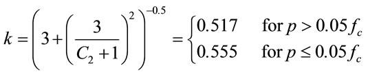 (19)
(19)
In engineering practice, such as in CFST bridges,  , hence
 (20)
(20)
It can be easily derived from Equations (16), (18) and (20) that
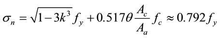 (21)
(21)
And
 (22)
(22)
When eccentric loading and stability are not considered, i.e.,  , Equation (5) can be simplified as
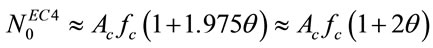 (23)
(23)
It can be seen from Equations (22) and (23) that the cross section resistance calculated using this proposed method is about  greater than that obtained from EC4 method. This difference can be regarded as a conservative simplification in EC4. The comparison of the cross section resistances calculated by this method and CECS and EC4 methods is shown in Figure 1. The difference among three methods is not significant. It should be pointed out that the CECS method is a conservative simplification from
 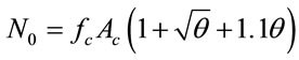 as illustrated in [6].

Figure 1. Comparison of the cross section resistances calculated with different methods.
3.2. The Influence of Slenderness
In EC4, the relative slenderness,  , is used to consider the influences of slenderness: 1) the confinement effect reduces with increase of
 ; 2) the stability decreases with increase of
 . In CECS, these two mechanisms are combined together into a factor,
  , which is obtained regressively from a large number of test data, adopting
  as a sole parameter, neglecting the configuration of
  and material properties; When
 , the UL of a CFST column is assumed to be governed by Euler buckling resistance.
As mentioned above, both methods are calibrated from test data. The different treatment on the slenderness influence between EC4 and CECS makes  in Equation (5) greater than
  in Equation (1). If the influence of
  on the confinement effect is considered, i.e.,
  , then an equivalent parameter can be derived, that is
 (24)
(24)
The comparison of the stability reduction factors of EC4 (neglecting the limit of ) and CECS is shown in Figure 2. It can be seen from this figure that: 1)
  values (the dash curves) are approximately the mirror of
  values (the solid curves) along the CECS curve; 2)
  has a significant influence on the reduction factor; 3) when
  reaches 20, the
  curves go together, which indicates
  is a divide for Euler buckling. Therefore, CECS and EC4 agree with each other again in this point, although the confinment effect is considered only when
 .
.
From Figure 2, it can be concluded that the influence of  is significant and therefore should be considered in the reduction factor. By observing the sinusoidal
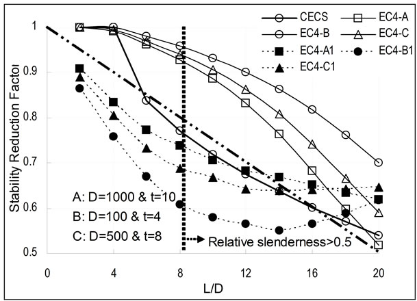
Figure 2. Comparison of stability reduction factors of ![]() (EC4-A, B & C),
(EC4-A, B & C), ![]() (EC4-A1, B1 & C1) and
(EC4-A1, B1 & C1) and  (unit of D and t: mm).
shape of the EC4 curves, a new method for predicting the stability reduction can be obtained, as shown in Equation (25).
 (25)
(25)
The parameter n in Equation (25) governs the shape of the curve. Through curve fitting, the curves agree well with both EC4 and CECS curves when , as shown in Figure 3. This factor, i.e., Equation (25), incorporates the advantage of
 , with extended slenderness boundary, and EC4, which includes the influence of
 .
.
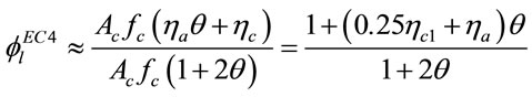
3.3. The Effect of Load Eccentricity
As the confinement strengthening effect reduces with eccentric loading, a reduction factor  is used to account for this change. This factor in CECS can be used in a wide range of eccentricity conditions, as shown in Equation (4), which stems from the M-N curve analysis followed by curve fitting [6]. However, in EC4, the load eccentricity induced influence is integrated into the calculation of cross section resistance when
 . Similar to
 , an equivalent factor,
  , can be obtained by letting
 .
.
 (26)
(26)
It is seen from Equation (26) that  is a function of both
  and
and![]() . However, in CECS, only the eccentricity is considered (see Equation (4)). The compareson of
. However, in CECS, only the eccentricity is considered (see Equation (4)). The compareson of  and
and  is shown in Figure 4. in which the
 ![]() is allowed to extend to 0.2. Although there is a huge difference between these two methods to deal with
is allowed to extend to 0.2. Although there is a huge difference between these two methods to deal with
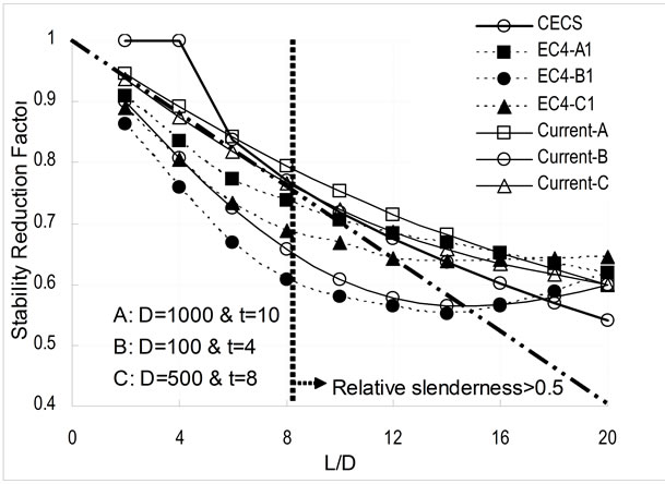
Figure 3. Comparison of stability reduction factors of  (current),
 ![]() and
and  (unit of D and t: mm).
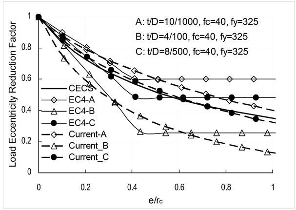
Figure 4. Comparison of the load eccentricity reduction factors of ,
,  and
and .
.
load eccentricity, the trend of reduction with eccentricity is similar. One compromise to this disagreement is to create an exponential function with both  and
and ![]() as its parameters, as given in Equation (27).
as its parameters, as given in Equation (27).
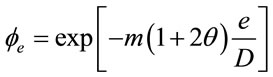 (27)
(27)
The  in Equation (27) is taken from Equation (23). The parameter m is used to calibrate curve fitting. It is found that when
 , the
, the  agrees well with both
  and
and , as shown in Figure 4.
4. The UL of CFST Columns Predicted by Current Method
From previous derivation, it is therefore proposed that the UL of a CFST column to be predicted by
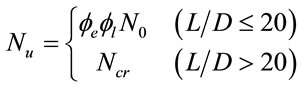 (28)
(28)
where ,
, ![]() and
and  can be calculated from Equations (22), (25) and (27), respectively. When
 , the UL is governed by the Euler buckling resistance.
4.1. The UL of Eccentrically Loaded CFST Columns
In order to understand the behaviour of eccentrically loaded CFST columns, Chen et al. [9] tested 18 specimens with various load eccentricity and  ratios. The specimen details, test results and UL predictions using different methods are listed in Table 1.
It is clear from Table 1 that when the load eccentricity is low, the EC4 prediction is fairly conservative. When the load eccentricity is high, the N-M curve has to be used. The UL predicted by current method is closed to but better than those predicted by CECS, which can be used even when the load eccentricity is high.
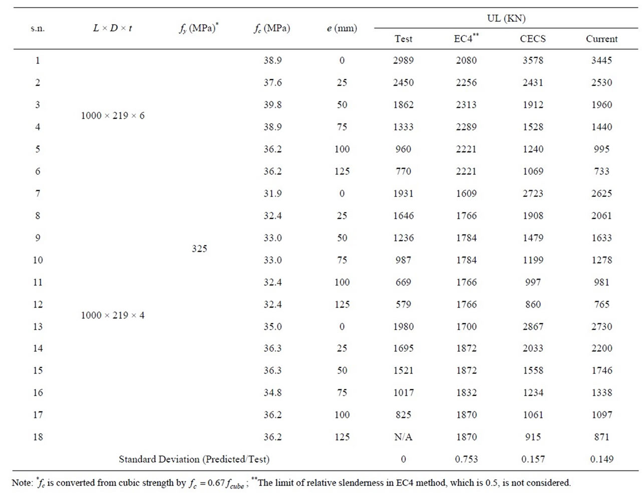
Table 1. Comparison of the predicted and measured ultimate load resistances of eccentrically loaded concrete filled steel tube columns.
4.2. UL of CFST Column with Various L/D
A number of CFST column tests with L/D vary from 3 to 50 were conducted during 1982 to 1983 by Cai et al. The specimen and test details can be found in [6]. Only the test results of specimens in Batch II are taken hereby. The UL of the specimens predicted by current method as well as those calculated using CECS and EC4 are compared in Figure 5.
Again, the EC4 prediction is conservative and the proposed method gives the best and smooth prediction results.
5. Conclusions
The UL of circular CFST columns can be predicted by various simplified methods with different consideration on confinement effect. These methods have their pros and cons. The EC4 method considers the influence of load eccentricity and slenderness on the confinement effect. The CECS method is simple and straight forward,
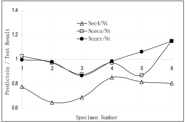
Figure 5. Comparison of the UL prediction of CFST columns by three different methods.
but cares less on the cross section parameters.
A simplified method is developed by inheriting the simple framework of the CECS method, but enriching the slenderness and load eccentricity reduction factors with cross section configuration influences in accordance with those implied by the EC4 method, so as to enable finer tuning capability than in CECS. Therefore, the proposed method makes the best of both EC4 method and CECS method.
The proposed method is derived from material properties in the limit equilibrium state, adopting the restrained concrete properties prescribed in EC2 and extending the boundary of load eccentricity and relative slenderness limit in EC4.
Validation against a series of tests shows that the proposed method can predict the UL of circular CFST columns with good accuracy.
REFERENCES
- Eurocode 4 (EC4), “Design of Composite Steel and Concrete Structures, Part 1.1: General Rules and Rules for Buildings,” Commission of European Communities, Brussels, 2004.
- American Institute of Steel Construction (AISC), “Manual for Structural Steel Buildings: Load and Resistance Factor Design (LRFD),” Chicago, 2005.
- AIJ, “Recommendations for Design and Construction of Concrete Filled Steel Tubular Structures,” Architectural Institute of Tokyo, Japan, 1997.
- China Association of Engineering and Construction Standardization-CECS 28:90, “Specification for Design and Construction of Concrete Filled Steel Tubular Structures,” China Planning Press, Beijing, 1991.
- The Electric Power Industry Standard of PRC: DL/T 5085-1999, “Code for Design of Steel-Concrete Composite Structure,” Issued by State Economic and Trade Commission of PRC, 1999.
- S. H. Cai, “Modern Steel Tube Confined Concrete Structures (Revised Edition),” China Communications Press, Beijing, 2007.
- J. Y. R. Liew and D. X. Xiong, “Effect of Preload on the Axial Capacity of Concrete-Filled Composite Columns,” Journal of Constructional Steel Research, Vol. 65, No. 3, 2009, pp. 709-722. doi:10.1016/j.jcsr.2008.03.023
- Eurocode 2 (EC2), “Design of Concrete Structures, Part 1-1: General Rules and Rules for Buildings,” Commission of European Communities, Brussels, 2004.
- B. C. Chen, Z. J. Ou, L. Y. Wang and L. H. Han, “Experimental Study on Carrying Capacity of Concrete Filled Steel Tubular Column under Eccentrically Load,” Journal of Fuzhou University-Natural Science Edition, Vol. 30, No. 6, 2002, pp. 838-844.
Nomenclatures
 : Steel area of the cross section of CFST column (mm2)
 : Concrete area of the cross section of CFST column (mm2)
D: Outer diameter of CFST column (mm)
e: Loading eccentricity (mm)
Ea, Ecm: Young’s Modulus of steel and secant modulus of concrete
 : Bending stiffness of CFST column,

L: Effective length of CFST column (mm)
 : Cross section resistance of CFST column calculated by method i
 : Ultimate load capacity of CFST column calculated by method i
 : Plastic resistance of the cross section of CFST column,
 : Euler buckling resistance of CFST column,
 ![]()
Ia, Ic: Second moment of inertias of steel tube and concrete core section P: Lateral confinement pressure on concrete core rc: Radius of concrete core
 ,
, : Current stability reduction factor and load eccentricity reduction factor
 ,
, : Stability reduction factor and load eccentricity reduction factor of method i
 : A factor considering the influence of internal axial reinforcing bars in EC4
 : Stability reduction factor in EC4
 : Relative slenderness,
![]()
 ,
, : Principal stresses in axial and lateral directions
 : Confinement effect factor,
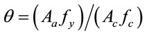
 ,
, : Strength adjustment factors for steel and concrete, respectively, in EC4
NOTES
*Corresponding author.