Open Journal of Biophysics
Vol.3 No.1A(2013), Article ID:28318,13 pages DOI:10.4236/ojbiphy.2013.31A013
Clinical Implementation of a 3D Dosimeter for Accurate IMRT and VMAT Patient Specific QA
Department of Medical Physics, Royal Adelaide Hospital, Adelaide, Australia
Email: thuc.pham@health.sa.gov.au
Received December 25, 2012; revised January 26, 2013; accepted February 5, 2013
Keywords: Delta4; IMRT; VMAT; Cross Calibration; Relative Array Calibration; Quality Assurance; Dose Linearity
ABSTRACT
The Delta4 3D dose verification device was commissioned in the current work for pre-treatment quality assurance (QA) of Intensity Modulated Radiotherapy (IMRT) and Volumetric Modulated Arc Therapy (VMAT) plans. The cross calibration and relative array calibration were performed to enable absolute dose comparison. The linearity of response with dose and temperature sensitivity tests were also conducted to investigate dosimetric properties of the Delta4 device. The need to modify the original CT image of the Delta4 phantom for accurate dose calculation and comparison is addressed in this work, applying a CT extension algorithm. A number of test plans varying from simple 4—field conformal to IMRT and VMAT plans were measured to evaluate the accuracy of this device. It was found that the Delta4 device measured dose accurately to within ±1%. In order to maintain this level of accuracy the machine output fluctuations need to be corrected prior to each measurement and the relative array calibration needs to be performed every six months.
1. Introduction
Increasing interest in the implementation of arc therapy, a radiotherapy technique in which the gantry of the linear accelerator is rotating while delivering the radiation dose to the patient, has triggered questions regarding the way quality assurance (QA) should be carried out for patient treatment plans. Arc therapy is another form of intensity modulated radiotherapy (IMRT) [1] in which not only the shape of the radiation field and the dose rate are varied over the entire treatment fraction but also the projection angle of the radiation field relative to the patient plane is also varying continuously. The traditional method using film and an ionisation chamber for quality assurance of arc and IMRT technique is time consuming and restricts the dose analysis to a two dimensional plane. Fast and accurate dose measurement in three dimensions is the most ideal. Delta4 [2] is a device that enables three dimensional dose maps to be measured inside a polymethylmethacrylate (PMMA) phantom replacing the patient anatomy. This is a relatively new device on the market with few studies published regarding its performance.
The dosimetric properties of the Delta4 device were investigated by Sadgopan et al. in 2009 [3] for IMRT pre-treatment QA. The authors tested the Delta4 device for reproducibility, stability, pulse-rate dependence, doserate dependence, angular dependence, linearity of dose response, and energy response. The interpolation algorithm of Delta4 software was also tested using various complex IMRT dose distributions. A total of 12 IMRT cases were taken into consideration in the evaluation of the Delta4 device. Using the gamma criteria of 3% dose difference (DD) and 3 mm distance to agreement (DTA) [4] and the dose threshold of 20%, the percentage of points which have gamma index ≤1 (pass rate) ranged from 98.7% to 62.9% with the head and neck case being the lowest. The reason for such a low pass rate was due to the normalisation point being incorrectly selected. This was rectified when the point in the high dose region was used as the normalisation point. It was also observed in this study that the reported pass rates were reduced when the angular and temperature dependence factors were ignored in the measurement. The difference between pass rate with and without the application of the angular and temperature dependence factors was not reported. The authors concluded that with the use of the proper normalisation point, the Delta4 device was sufficiently accurate for IMRT QA measurements.
Feygelman et al. [5] evaluated the performance of the Delta4 device for IMRT QA measurements using a helical tomotherapy delivery. The linearity, short-term reproducibility, dose rate dependence, relative array sensitivity and array cross-calibration were investigated. Film was used to verify the relative sensitivity correction factor applied in the Delta4 software. The quality assurance measurements were then performed for 9 clinical plans. An average pass rate of 97% for a 3% DD and 3 mm DTA gamma criteria was achieved for these plans. The authors found that it was necessary to use the megavoltage computing tomography (MVCT) feature of the tomotherapy machine for accurate positioning of the Delta4 device.
A comparison between the Delta4 device and traditional film and ionisation chamber IMRT QA results for 5 clinical tomotherapy IMRT plans was reported by Guert et al. in 2009 [6]. The authors wanted to determine whether it was suitable to replace the traditional dose verification method with the Delta4 device for IMRT quality assurance. It was found that the point dose measured by the Delta4 device agreed within 0.7% with the ionisation chamber measurement in the low dose gradient region. A minimum gamma pass rate of 97% was achieved for the comparison between Delta4 measured dose maps and the planned dose maps when using the 3% DD and 3 mm DTA gamma criteria. The study also found that the amount of time saved per plan when using Delta4 device was at least 1 hour. The authors then used Delta4 device for quality assurance of 264 IMRT plans and found that all plans had a pass rate over 90% for 3% DD and 3 mm DTA gamma criteria.
Bedford et al. 2009 [7] evaluated the performance of the Delta4 device for IMRT and Volumetric Arc Therapy (VMAT) (a trade mark term used by the linac manufacturer ELEKTA to refer to arc therapy) plan verification. Angular response, dose and dose rate dependence were studied. The accuracy of the Delta4 device for measuring absolute dose was checked using film and an ionisation chamber. The maximum difference between Delta4 and the ionisation chamber point dose measurements was 2.5%. The Delta4 measured dose distribution agreed with Pinnacle TPS better than film data did.
Quality assurance of RapidArc (a trade mark term used by the linac manufacturer Varian to refer to arc therapy) plans using Delta4 was also reported by Korreman et al. in 2009 [8]. 9 IMRT test cases were planned using Varian Eclipse 8.5 TPS and delivered by a Varian linear accelerator in this study to determine the accuracy of delivery of a RapidArc plan. The authors found that Delta4 results were reproducible and the device could achieve more than 95% gamma pass rate for the comparison of planned and measured data.
Feygelman et al. [9] used Delta4 to evaluate the accuracy of a beta version of Philips Pinnacle TPS for VMAT planning. A total of 50 test plans created by the AAPM [10] for multi-institutional comparison of IMRT dosimetry were used for this investigation. Gamma pass rates ranging from 94.5% - 99.9% were observed when using 4˚ gantry control point spacing for plan optimisation. While the 6˚ control point spacing reduced the planning time, it is not appropriate for high intensity modulated plans.
Fotina et al. 2011 [11] used Delta4 measured dose maps as a benchmark for comparing the accuracy of the Enhanced Collapsed Cone and new Monte Carlo algorithms in the Oncentra Master Plan and Monaco treatment planning system respectively. 8 IMRT and 2 Stereotactic Body Radiotherapy (SBRT) plans were involved in this study. Both planning systems were found to meet the clinical dosimetric standard as the mean dose prediction error in the PTV were below 3%. Comparison between the Delta4 measured dose map and planned dose map revealed that dosimetric accuracy in high dose gradient regions remains a challenge for both planning systems.
The use of the Delta4 device for IMRT and VMAT patient pre-treatment quality assurance has been validated in the current work. While there is a similarity between the tests completed in this work and in the published literature, an additional procedure implemented in this work (to allow for a more realistic comparison between the planned and measured dose maps) was not reported previously. This procedure involved modification of the manufacturer provided computed tomography (CT) images of the Delta4 phantom. These images are used in the TPS for dose calculation. This step will be described in this report in addition to the calibration and characterisation tests prior to the clinical implementation of the Delta4 device. In addition, to our knowledge there are only 6 devices in clinical use at present in Australia and New Zealand. With the increase in VMAT use, the need for 3D dosimetric verification devices will increase as well. The authors believe that the readers will benefit from the information provided in this work.
2. Method
Delta4 is capable of measuring absolute dose in the cylindrical PMMA phantom. The measurement is synchronised with the linear accelerator (linac) by detecting the trigger pulse signal from the linac. In order to ensure that the dose is measured accurately and to gain a full understanding of the features and limitations of Delta4, the following tests were performed:
1) Cross calibration with ionisation chamber;
2) Detector response calibration;
3) Linearity check;
4) Directional response correction;
5) Temperature response check;
6) Four fields plan verification;
7) IMRT and VMAT plan verification.
2.1. Cross Calibration
Cross calibration of the Delta4 detector was performed against the reference NE2571 Farmer ionisation chamber with a known dose calibration factor traceable to ARPANSA [12] The procedure recommended by the vendor [2] was reviewed and found to be in agreement with the general recommendations provided by the IAEA TRS398 [13] protocol for cross calibrating a dosimeter.
Figure 1 shows the cross calibration measurement setup as performed in this work for a 6 MV photon beam from the Synergy MLCi2 ELEKTA [14] linac. In the first measurement the Farmer chamber was placed inside the PMMA jig sandwiched between the PMMA build-up and the back-scatter material. The water equivalent thickness of this material had been determined using the density scaling technique. It was found that in this setup, the depth of the Farmer chamber in the jig was equivalent to 5 cm depth in water. The effective point of measurement was taken to be at the centre of the Farmer chamber. The reason for this is because the beam quality correction factor kQ,Qo [13] used for dose calculation based on TRS 398 protocol accounts for the displacement correction factor.
In the second measurement, the Delta4 detector planes were disassembled from the cylindrical phantom so that they could be placed in another solid phantom jig. This jig was also designed by the vendor to place the detector planes at a water equivalent depth of 5 cm. Both the reference Farmer chamber and the Delta4 detector planes were irradiated with the same number of monitor units (100 MU), dose rate (600 MU/min), 10 × 10 cm2 radiation field size, 95 cm source to surface distance (SSD) and 100 cm source to chamber distance (SCD).
The TRS 398 formalism was adopted for dose calculations. For the measurement performed with the NE2571 Farmer chamber at a depth of 5 cm water, the dose was calculated as follows:
 (1)
(1)
where kTP is the correction factor which accounts for changes in the collected charge due to the variation of temperature and pressure in the atmosphere; ks is the recombination factor and kp is the polarity correction factor.
 is the charge to absorbed dose in water calibra tion factor and M1 is the average charge collected in three measurements.
The absorbed dose in water as measured by the Farmer chamber was entered into the Delta4 program. The dose calibration factor CFD was then calculated based on the response (R) of the diode detectors as measured during the cross calibration as follows:
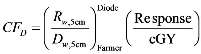 (2)
(2)
This factor has unit of diode response per cGy. The absorbed dose in water DDelta4 as measured by the Delta4 detector can therefore be derived from the measured response of the Delta4 diode detectors in any measurement condition as follows:
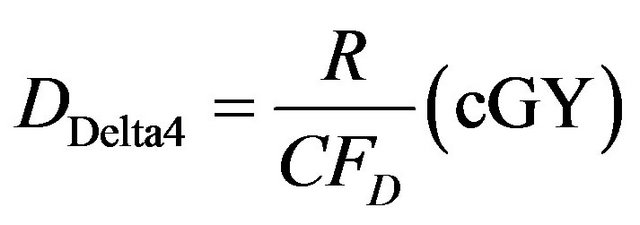 (3)
(3)
2.2. Relative Array Calibration
The 1069 diode detectors do not have the same response even for the same irradiation conditions. The non-uniformity in response of the Delta4 detectors can be corrected by the software using the data acquired from the discussed procedure below.
Figure 2 shows the setup for array calibration. This is

Figure 1. Cross calibration of the Delta4 detectors against the reference Farmer Chamber setup. It should be noted that the Delta4 detectors had been disassembled from the cylindrical phantom. The measurement was first conducted with the Main unit tightly positioned in the Delta4 detector plane jig. The main unit was then replaced with both the Upper Wing and Lower Wing units in one single measurement.

Figure 2. Setup for relative array calibration used for correcting the non-uniform response of the diode detectors.
the same setup as for the cross calibration except the field size was changed from 10 × 10 cm2 to 26 × 26 cm2 to cover all the detectors. The measurement was performed over 7 different positions A, B, C, D, E, F and G as shown in Figure 2. Extra PMMA layers were placed on the side when measurements in positions D, E, F and G were performed to allow for sufficient side scatter.
2.3. Linearity Check
The Delta4 detectors were checked for linearity in response as a function of the linac output (or Monitor Units). The measurement was setup in the exact same way as for the patient specific QA measurement used at our centre. The source to detector distance (SDD) is 100 cm and the centre of the Delta4 phantom was setup using the lateral lasers and the cross hair. The linearity check was performed using a range of MUs from 4 - 500. This range of MUs was chosen because it had been verified previously that the linear accelerator dose output is linear within this range. The linearity index for a particular monitor unit MU (IMU) was calculated using the following formula:
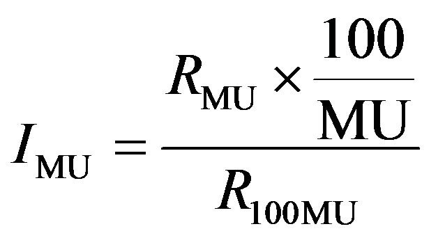 (4)
(4)
where RMU is the dose output measured with a particular monitor MU and R100 is the dose output measured with 100 MU.
The linearity index was calculated for each detector and MU of 4, 5, 10, 50, 100, 250 and 500. The percentage of detectors that has linearity index less than and equal to 1% for each MU was plot on the bar graph to assess the linearity response of the Delta4 detectors.
2.4. Directional Response Correction
The response of the detector planes in the Delta4 cylindrical phantom is different at different beam gantry angles. This is caused by the additional attenuation through the Printed Circuit Board (PCB) underneath the diode detectors. The PCB was observed in the CT image of the Delta4 phantom. The maximum difference in the detector response occurs between opposing beams that are normal to the detector plane. This maximum difference was measured using the same setup as in the relative array calibration (refer to Figure 2) measured in position A. The measurement was performed on both the Main and Wing units. Each unit was irradiated twice at a fixed gantry angle 0˚ but the detector plane flipped by 180˚. The correction factor is calculated automatically by the software. The user has an option to either apply or ignore the directional dependence of the Delta4 detector.
2.5. Temperature Response Check
It was found that the diode detector response varies with temperature [2] and this is the reason why the ambient temperature needs to be entered into the Delta4 software prior to every measurement. The magnitude of the change in detector’s response was investigated. This was carried out by changing the temperature in the software and recording the signal of a single detector. All other detectors in the array were assumed to respond to temperature in the same way.
2.6. Four-Field Plan Verification
Once the cross calibration and the dosimetric characteristic tests for the Delta4 had been performed, the accuracy of absorbed dose measurement with a clinical plan delivery was assessed. This was investigated using a 20 × 20 cm2 radiation field and irradiating the detector at gantry angles at 0, 90, 270 and 180 degrees with equal beam weighting. Two plans were generated with a prescription of 20 MU and 200 cGy to a point respectively. The 20 MU prescription was investigated because this is the minimum MU where the Delta4 detectors showed linearity in their response. The absorbed dose in the Delta4 phantom was calculated by the Pinnacle TPS [15]. Computed Tomography (CT) scans of the Delta4 phantom without the embedded diode detector was used for this purpose because the diode detector introduces high density artifacts. The contour was drawn over the CT image of the Delta4 phantom and the physical density of 1.19 g·cm−3 was assigned to this contour.
The absorbed dose in the Delta4 phantom from the 4- field plan was measured using the SAD setup. The centre of the phantom was aligned to the linac iso-centre using the lateral and sagittal lasers. The calibration field was measured prior to the 4-field plan to obtain the Daily Correction Factor (DCF). The DCF serves 2 purposes; it corrects for the variation of the linac output and reduces the uncertainty in the measured dose due to the uncertainty in estimating the physical density of the Delta4 phantom. The DCF was calculated by the software based on the planned and measured dose in the Delta4 phantom using the same setup and beam parameters. In this work the setup was as per the 4-field plan except 200 MU was used at a single gantry angle of 0˚.
2.7. IMRT and VMAT Plan Verifications
Since the primary use of Delta4 is to perform pre-treatment dose verification check for IMRT and VMAT plans, it is essential that in the commissioning process these types of plan are checked prior to releasing Delta4 for clinical use. For this purpose, two clinical head and neck IMRT plans and one non-clinical prostate VMAT plan were used (VMAT function in the planning system had not been commissioned for clinical used at the time). These plans were initially created on a real patient CT density map and then copied into the cylindrical Delta4 phantom CT density map. The head and neck case was chosen because it had a large number of control points, a large range of segment sizes and intensity modulation. This made it easier to investigate issues with small field dosimetry and high dose gradient regions. The VMAT plan on the other hand was chosen to investigate the feasibility of VMAT delivery on our new Elekta Synergy linac and also to see how well the plan and delivered doses agreed.
2.8. Modification of the CT Image of the Delta4 Phantom
The CT image size of the Delta4 phantom provided by the vendor was smaller than the patient CT image size (comparing Figures 3(a) and (d)). When importing the Delta4 phantom into pinnacle to create a QA plan, the same image size was maintained (Figure 3(c)). This became a problem when the region of interest (ROI) (Figure 3(d)) from the patient plan was imported into the Delta4 QA plan as shown in Figures 3(d) and (e). The patient contour originally drawn in a bigger CT image size, was now projected onto a smaller CT image size and thus some part of the ROI were projected onto an undefined space (dark brown region in Figures 3(b), (c), (e) and (f)) in the Delta4 QA plan (Figure 3(f)). When this happened, the Delta4 QA plan from Pinnacle could not be exported to the Delta4 computer, which was required to perform measurement.
The problem shown in Figure 3 was overcame by using an in-house Matlab [16] program to introduce an additional air region around the Delta4 phantom CT image to match the patient CT image size. This will ensure that none of the ROI drawn in the patient plan will be projecting in the undefined space in the Delta4 QA plan. More accurate dose volume histogram comparison can be achieved with this method comparing to shrinking the patient ROI to fit the original CT image.
3. Results and Discussions
3.1. Cross Calibration
The absorbed dose in the PMMA phantom as measured by the NE2571 farmer chamber in the cross calibration procedure was 0.947 Gy. This was 2.5% higher than the absorbed dose measured with the same setup in liquid water. This difference was expected because of the following error contributing factors estimated by the IAEA TRS 398 dosimetry protocol [13]: Differences in the mass energy absorption coefficient and scatter conditions between water and PMMA, uncertainties arising from the establishment of reference condition (±0.4%), variation of detector signal relative to linac output (±1%), the uncertainties due to the correction for kTP, ks, and kp (±1%) parameters and beam quality correction (±1.4%) as well as the standard deviation of the calibration procedure of the reference farmer chamber at the secondary standard laboratory (±0.6%). The total uncertainty was estimated to be ±2.1%.
As mentioned in the previous section a calibration field measurement is required prior to the pre-treatment QA measurement. By using the calibration field, the uncertainty due to both the fluctuation in the beam output and the use of an estimated density value of the Delta4 phantom can be minimised. The total uncertainty in measuring dose using the Delta4 device is then reduced to ±1.7%.

Figure 3. The problem with importing smaller CT image size than the real patient CT image is illustrated in this figure. The result is that the patient contour drawn in the real patient plan overlapped with the undefined space in the Delta4 QA plan as seen in (f).
3.2. Relative Array Calibration
The manufacturer acceptance criteria for the array calibration are that 90% of the detectors should have responses within ±0.5% of each other and none of the detectors should have a response different greater ±2% for the same dose. In this commissioning work, 91% of the Wing units detectors were within ±0.5% and 100% of the Main unit detectors were within ±0.5% Another acceptance criterion for this response test is that all detectors should have signal strength greater than 70% relative to the central detector. It was observed in this work that all of the detectors in the Main and Wings Units measured signal more than or equal to 85% and 87% relative to the signal strength of the central detector respectively.
3.3. Linearity Check
Figure 4 shows the linearity test results measured by the Wing and Main detectors using 4 MU and 5 MU. The blue and red areas represent the percentage number of detector that has linearity index greater than and less than or equal to 1% respectively. Our acceptance criteria was less than or equal to 1%. The national tolerance [17] value for linearity check for the local reference dosimeters is 0.5%. Since the detectors in Delta4 are diode detector 1% is considered acceptable [18].
It can be seen from Figure 4 that the detectors in the Wing Units are less linear than those in the Main Unit when 4 MU was used. The Wing Unit has a significant amount of detectors that failed to meet our criteria of 1%

Figure 4. Dose Response Linearity results for the Wing and Main units irradiated with 4 MU and 5 MU. The blue and red areas represent the percentage of detectors has linearity index greater 0.01 and less than or equal 0.01.
at 4 MU. Only 1.1% number of detectors has linearity index greater than 1% when 5 MU were used. The linearity indices for higher MU were also analysed, but are not shown in this report, showed that none of the detector in the Delta4 phantom has linearity index greater than 1. It was therefore decided that 5 MU is the minimum MU to be used for each segment in the clinical IMRT plan.
3.4. Directional Response Correction
It was reported in the Delta4 user manual that the directional response correction factor makes at most ±0.5% difference to the final dose measurement result. Since this is a minor correction, no further investigation was performed to verify the reported result in this work. However, to maximise the accuracy of the Delta4 detector, the directional response correction was measured and decided to apply in all future quality assurance measurements.
3.5. Temperature Response Check
It was found that the signal changed linearly with temperature. A temperature change of 2.5 degree Celsius changes the signal by 0.65% that is 0.26%/˚C. The decrease in temperature results in an increase in the signal.
3.6. Four-Field Plan Verification
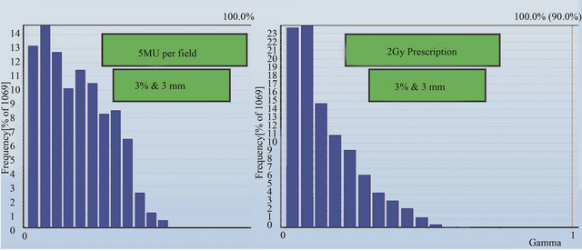
The DVH, gamma analysis and detector point dose were compared against the Pinnacle3 planned dose in Delat4 phantom. The DVH in Figure 5 shows the planned and measured doses in green and red lines respectively. Figure 5(a) shows the prescription of 5 MU per field and Figure 5(b) shows the prescription of 2 Gy. The slight disagreement in 5 MU prescription was caused by the difference in the planned and measured dose grid resolution. The 2 Gy prescription shows a dose difference of about 1% in the 95% volume. The result shows that for at least 95% of the planned volume, the planned and measured doses are within 1% of the prescription dose.
A gamma analysis was also performed for planned and measured doses in the detector plane of the Delta4 phantom. Figures 6(a) and (b) show the gamma results for 5 MU per field and 2 Gy prescriptions respectively. The criteria set for the gamma analysis are 3% and 3 mm for dose and distance-to-agreement conditions respectively with a dose threshold of 30% of the prescription dose. The results in Figure 6 shows that the planned and measured doses at every detector position in the Delta4 phantom pass the gamma analysis.
 (a) (b)
Figure 5. Dose Volume Histogram (DVH) for planned and measured dose in Delta4 cylindrical phantom. Red line is planned and green line is measured data.
 (a) (b)
Figure 6. Gamma analysis results for the planned and measured dose at all detector positions for (a) 5 MU per field and (b) 2 Gy prescription.
Point to point dose comparison was carried out for these 2 prescriptions. Various planned and measured profiles across the detector planes are shown in Figures 7-10. Figure 7 shows the comparison across the outer most edge detectors in the cross plane for a) 5 MU per field and b) 2 Gy prescription. The discrepancy shown here is caused by a number of factors: the lack of lateral scatter in the measurement, the scatter contribution from the metal bar handle attached to the Delta4 phantom, the effect of positioning error is larger for those detectors near the beam penumbra and the uncertainty in the calculated dose near the interface between PMMA phantom and air. This discrepancy seems to reduce for the 2 Gy prescription as seen in Figure 7(b)). Some of the central detectors were under responding for a reason that could not be explained.
Comparison between the planned and measured doses at other positions (Figures 8-10) in the Delta4 detector planes showed that agreement within 1% can be achieved at all positions indicated by the blue line in these figures. It was noticed for both the in-plane and the cross-plane direction that the discrepancy between the planned and measured doses increases for those detectors that are further away from the centre of the phantom.
3.7. IMRT and VMAT Verification Plans
Figures 11-13 show the gamma analysis and DVHs for the clinical head and neck and prostate cases planned in IMRT mode and prostate case planned in Smart Arc mode in Pinnacle TPS. The dose deviation, DD (left), distance-to-agreement DTA (middle), and gamma index (right) for these comparisons are displayed together for each patient plan. Delta4 software calculated these results based on the algorithm reported by Low et al. 1998 [4]. The gamma criteria were 3% DD and 3 mm DTA with a dose threshold of 30%. The plan was considered to pass for a gamma value above 90%, meaning that atleast 90% of the measured positions in the Delta4 phantom passed the gamma criteria. The dose threshold level was used to avoid comparison in the insignificant low dose regions. Based on the literature [7], results observed in this work and previous experience with IMRT quality assurance on a 2D matrix device [19], the 3% DD and 3 mm DTA and dose threshold of 30% were found to be appropriate gamma analysis parameters.
Figures 11 and 12 show that the dose deviation results for the head and neck plans were well under the 90% pass rate. This is because of a large number of high dose gradient regions in the Head and Neck plan which were created in response to multiple critical organ dose limits in the vicinity of the tumour. The high percentage in the DTA result implies that the setup error is small. The gamma analysis incorporates both the dose deviation and distance to agreement to account for the high dose gradient in the treatment plan. It can be seen that the gamma result for these head and neck plans passed the 90% level, in fact better 95% level were achieved. The VMAT prostate plan result (Figure 13) on the other hand passed dose deviation and gamma analysis. This result is expected because of the simplicity of the prostate plan. It should be noted that gamma indices in these plans were calculated relative to the prescription dose. This is called global [4] gamma analysis. The local gamma analysis method [4] is also available in the Delta4 software for assessing point to point agreement. Although the local gamma method gives more accurate gamma analysis, the global gamma method provides results relative the total plan dose which is clinically more relevant.
4. Conclusions
The ScandiDos Delta4 phantom for 3D dose verification has been commissioned and met the criteria to be used clinically. The cross calibration, relative measurement, linearity and directional response correction were performed. Based on these measurements, the uncertainty in the dose measurement using the Delta4 phantom was estimated to be ±1.7%. This uncertainty is result in part from the error in the cross-calibration process. The comparison between Pinnacle calculated and Delta4 phantom dose for a simple four orthogonal fields plan was carried out to assess the accuracy of the Delta4 phantom and also to establish a baseline. It was found that agreement of ±1% between the planned and measured doses was achieved for most detectors in the phantom except for the outer most row and column detectors. In addition, the Gamma analysis of these four fields plan results show that 100% of the data points had a gamma index less than 1 for the 3% and 3 mm dose and distance-to-agreement criteria.
Additional tests were performed to study the detector response with room temperature. Because of the significant change in the detector signal with temperature (0.26%/˚C), it is essential that the temperature is entered into the software before the measurement takes place. Based on experiences gained during the commissioning process, it is also recommended that in order to maintain the uncertainty in measuring the absolute dose, routine quality assurance needs to be performed for the Delta4 phantom. The cross calibration should be performed every year or after the beam output has been adjusted. The detector sensitivity is expected to change due to radiation damage. The manufacturer has specified a change of less than 1% over 1000 Gy. We expect to treat roughly about 10 patients per week. To keep the uncertainty due to radiation damage well under 1%, it was decided that the sensitivity correction and linearity should be performed every six months.


Figure 7. Point to point comparison between the planned and measured dose along the outer most edge detectors for 5 MU per field and 2 Gy prescription.


Figure 8. Point to point comparison between the planned and measured dose along different line in the cross plane using 5 MU per field prescription.
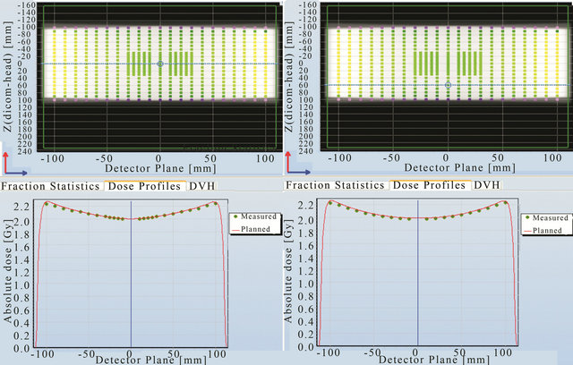
Figure 9. Point to point comparison between the planned and measured dose along different line in the cross plane using 2 Gy prescription.

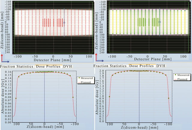
Figure 10. Point to point comparison between the planned and measured dose along the in-plane line in the detector plane using 5 MU per fields and 2 Gy prescription.
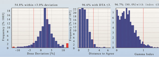
Figure 11. The dose deviation (left), distance to agreement (middle) and global gamma index (right) for the patient plan A.
Prior to releasing the Delta4 device for clinical use, two head and neck IMRT and one VMAT plan were trialled. All of these plans were passed well above the 95% level when using the gamma criteria of 3% and 3 mm and the dose threshold 30%. It was found that the use of dose deviation analysis alone was not sufficient to determine whether the plan passed or failed. The same gamma analysis criteria were decided to be used for as-

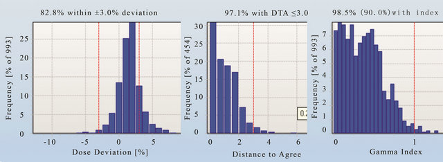
Figure 12. The dose deviation (left), distance to agreement (middle) and global gamma index (right) for the patient plan A.

Figure 13. The dose deviation (left), distance to agreement (middle) and global gamma index (right) for the patient plan C.
sessing future clinical plans.
5. Acknowledgements
I would also like to thank the medical physics team at the Nepean Cancer Care Centre for contributing ideas for this project in many of our physics meetings. I also like to thank Associated Professor Eva Bezak for her great effort in the editing process of this paper. Finally, I would to acknowledge Dr. Paul Reich for his idea in building the Matlab code that was used in this work and Dr. Scott Penfold and Joshua Moorrees for doing the proof reading.
REFERENCES
- J. V. Dyk, “The Modern Technology of Radiation Oncology: A Compendium for Medical Physicists and Radiation Oncologist,” Medical Physics Publishing, Vol. 2, 2005.
- ScandiDos, “User Technical Help Manual,” ScandiDos, Uppsala, 2010
- R. Sadagopan, J. A. Bencomo, R. L. Martin, G. Nilsson, T. Matzen and P. A. Balter, “Characterization and Clinical Evaluation of a Novel IMRT Quality Assurance System,” Journal of Applied Clinical Medical Physics, Vol. 10, No. 2, 2009, p. 2928. doi:10.1120/jacmp.v10i2.2928
- D. A. Low, W. B. Harms, S. Mutic and J. A. Purdy, “A Technique for the Quantative Evaluation of Dose Distributions,” Medical Physics, Vol 25, No. 5, 1998, pp. 656- 661. doi:10.1118/1.598248
- V. Feygelman, D. Opp, K. Javedan, A. J. Saini and G. Zhang, “Evaluation of a 3D Diode Array Dosimeter for Helical Tomotherapy Delivery QA,” Medical Dosimetry, Vol. 35, No. 4, 2010, pp. 324-329. doi:10.1016/j.meddos.2009.10.007
- M. S. Geurts, J. M. Gonzalez and P. Serrano-Ojeda, “Longitudinal Study Using a Diode Phantom for Helical Tomotherapy IMRT QA,” Medical Physics, Vol. 36, No. 11, 2009, pp. 4977-4983.
- J. L. Bedford, Y. K. Lee, P. Wai, C. P. South and A. P. Warrington, “Evaluation of the Delta4 Phantom for IMRT and VMAT Verification,” Physics in Medicine and Biology, Vol. 54, No. 9, 2009, pp. 167-176. doi:10.1088/0031-9155/54/9/N04
- S. Korreman, J. Medin and F. Kjær-Kristoffersen, “Dosimetric Verification of RapidArc Treatment Delivery,” Acta Oncologica, Vol. 48, No. 2, 2009, pp.185-191. doi:10.1080/02841860802287116
- V. Feygelman, G. Zhang and C. Stevens, “Initial Dosimetric Evaluation of SmartArc—A Novel VMAT Treatment Planning Module Implemented in a Multi-Vendor Delivery Chain,” Journal of Applied Clinical Medical Physics, Vol. 11, No. 1, 2009, p. 3169.
- G. A. Ezzell, J. W. Burmeister, N. Dogan, T. J. LoSasso, J. G. Mechalakos, D. Mihailidis, A. Molineu, J. R. Palta, C. R. Ramsey, B. J. Salter, J. Shi, P. Xia, N. J. Yue and Y. Xiao, “IMRT Commissioning: Multiple Institution Planning and Dosimetry Comparisons,” American Association of Medical Physics, Vol. 36, No. 11, 2009, pp. 5359- 5373.
- I. Fotina, G. Kragl, B. Kroupa, R. Trausmuth and D. Georg, “Clinical Comparison of Dose Calculation Using the Enhanced Collapsed Cone Algorithm vs. a New Monte Carlo Algorithm,” Strahlentherapie und Onkologie, Vol. 187, No. 7, 2011, pp. 433-441. doi:10.1007/s00066-011-2215-9
- Secondary Dosimetry Standard Laboratory, “Departmental Calibration Report on a Therapy Ionization,” Australian Radiation Protection and Nuclear Safety Agency, Miranda, 2010.
- IAEA, “Technical Reports Series 398, Absorbed Dose Determination in External Beam Radiotherapy, an International Code of Practice for Dosimetry Based on Standards of Absorbed Dose to Water,” International Atomic Energy Agency, Vienna, 2000
- ELEKTA, “Precise Digital Accelerator Synergy MLCi2,” ELEKTA Limited, Sydney, 2010.
- Philips Medical Systems, “Pinnacle3 Radiation Therapy Planning System,” Version 9, 2010.
- Mathworks Inc., “Matlab Version 2010a,” 2010.
- M. Millar, J. Cramb, et al., “Supplement ACPSEM Position Paper, Recommendation for the Safe Use of External Beams and Sealed Brachytherapy Sources in Radiation Oncology,” Australasian Physical and Engineering Sciences in Medicine, Vol. 20, No. 3, 1997, pp. 1-35.
- J. G. Li, G. Yan and C. Liu, “Comparison of Two Commercial Detector Arrays for IMRT Quality Assurance,” Journal of Applied Clinical Medical Physics, Vol. 10, No. 2, 2009, p. 2942. doi:10.1120/jacmp.v10i2.2942
- IBA Dosimetry, “OmniPro IMRT 2D Array,” IBA, Germany, 2001.