Journal of Power and Energy Engineering
Vol.04 No.04(2016), Article ID:66209,12 pages
10.4236/jpee.2016.44009
The Design of PSM-Based ECRH Power Supply Control System
Jian Zhang, Xu Hao, Wei Wei, Yiyun Huang
Institute of Plasma Physics Chinese Academy of Sciences, Hefei, China

Copyright © 2016 by authors and Scientific Research Publishing Inc.
This work is licensed under the Creative Commons Attribution International License (CC BY).
http://creativecommons.org/licenses/by/4.0/


Received 3 March 2016; accepted 16 April 2016; published 29 April 2016
ABSTRACT
Electron cyclotron resonance heating (ECRH) system is one of the most important Tokamak auxiliary heating methods. However, there are growing demands for ECRH system as the physical experiments progress which meanwhile adds the difficulty of designing and building the control system of its power source. In this paper, the method of designing a control system based on Single Chip Microcomputer (SCM) and Field Programmable Gate Array (FPGA) is introduced according to its main requirements. The experimental results show that the control system in this paper achieves the conversion of different working modes, gets exact timing, and realizes the failure protection in 10us thus can be used in the ECRH system.
Keywords:
ECRH, PSM High Voltage Power Supply, Control System, Field Programmable Gate Array (FPGA), Single Chip Microcomputer (SCM)

1. Introduction
The auxiliary heating systems are the most important and the most complex devices of Tokamak, which as a result are concerned by the related experts for years [1] . Since the first Tokamak experimental facility was built in 1954, the auxiliary heating system experienced from the short pulse period to long pulse period, and finally to steady state period, meanwhile, different designs of designing the auxiliary heating HVDC (High Voltage Direct Current) power supply were generated. Generally, there are 3 technical routes, the first is based on tetrode, the second is based on thyristor and the last one is based on PSM (Pulse Step Modulation) switching power supply technology [2] . The circuit configuration of PSM HVDC power supply for ECRH system is shown in Figure 1 [3] .
The power source system is composed of the power distribution cabinet, the soft start switch cabinet, the multiwinding transformer, the PSM modules, the detection devices, the protection and control units etc. Multi identical

Figure 1. Circuit configuration of −60 kV/50A PSM HVDC power supply.
83 PSM modules and 1 BUCK module make up a PSM power supply system. The stabilized high-voltage DC output is obtained by connecting all the power modules in series. Different kinds of output voltage waveform can be gotten by controlling the IGBT of each power module. The output voltage of the step module is 810VDC and the output voltage of the BUCK module is Ds × 810V (Ds is the duty cycle of BUCK, 0 ≤ Ds ≤ 1). Therefore, the maximum output voltage of the ECRH PSM power supply is 68.04 kV which exceeds the requirement 60 kV. Compared with the other auxiliary heating power sources, the control system of PSM HVDC power source is even more complicated for the following 4 reasons [4] :
1) The number of controlled member is increased. In the PSM power supply, besides the power distribution cabinet and the soft start switch cabinet, the controlled objects also include the 84 PSM modules which increase the difficulty of designing the control system.
2) The control course is more complex. One single working process of the PSM power source consists of 7 phases:
Phase 1: close the power distribution cabinet;
Phase 2: close the soft start cabinet;
Phase 3: short out the soft start resistance;
Phase 4: turn on the desired PSM modules;
Phase 5: turn off the PSM modules when the working time is up;
Phase 6: open the soft start switch;
Phase 7: open the power distribution cabinet.
All the logical and sequential controls are realized by the control system:
3) The PSM power source has higher standards of control speed and accuracy.
a) The PSM modules can be turned on or turned off in sequence at a time interval of a minimum and accurate 1us;
b) The power source should be shut off in 10 us when any failure happens. Highly demanded power source adds the difficulty to design and build its control system.
4) The PSM power source has different running modes to satisfy the experimental demands of ECRH system which adds the difficulty of designing the control system.
2. Analysis of the Requirements of PSM Power Supply Control System
The main tasks of the PSM control system include turning on or turning off the switch cabinets and PSM modules, measuring the output voltage and current, setting the operating parameters, monitoring the working condition and protecting the key devices etc. [5] . Specifically, the requirements of the PSM Power source used for ECRH system can be divided into the following 4 aspects:
2.1. Controlling the Switching Cabinet and PSM Module
By controlling the switching cabinets (the power distribution cabinet and the soft start switch cabinet) and PSM modules, we can control the working condition of the PSM power supply which allows us to turn on and turn off the whole system in accordance with the desired 7 steps.
What’s more, a big challenge of the ECRH power source is making sure the overshoot of the output voltage under 2% meanwhile its rising and falling time are no more than 100 us. According to the control strategy, when the PSM modules are turned on one by one, the output voltage overshoot will decrease significantly, and to make sure the output voltage can be established in 100 us under any condition, the control system should have the ability to turn on and turn off the PSM modules in sequence at a time interval of a minimum and accurate 1 us.
2.2. Setting the Working Mode of the PSM Power Source
Theoretically, we can get any kind of the output voltage which is just the sum of the output voltages of the working PSM modules. As for the ECRH system, there are mainly 2 working modes, pulse mode and modulation mode, which are shown in Figure 2. The mission of the control system is allowing the operator set the 2 work modes easily and conveniently.
2.3. Monitoring the Working Condition of the Power Supply
One of the main tasks of the control system is monitoring and showing the condition of the key parts of the power supply to make sure the whole ECRH system runs smoothly and safely. Mainly, there are 4 kinds of monitoring objects:
1) The conditions of the power distribution cabinet and the soft start switch cabinet;
2) The running status of the PSM modules;
3) The output voltage and output current which should be measured and shown in real time;
4) The fault conditions of the ECRH system including the over-current fault, the over-voltage fault, crowbar failure and the electron cyclotron failure.
2.4. Protecting the Electron Cyclotron as Well as the Power Source Itself
The electron cyclotron, which serve as the load of the PSM HVPS, are the key parts of the ECRH system. If anyone of them is damaged, a great economic loss will be produced and the whole experimental progress will be delayed. Thus, another important mission of the control system is protecting the load of the power supply. In other words, the control system could realize different kinds of protection at a really high speed (20 us according to the requirement). To make sure the safety of the electron cyclotrons and the operators, the control system has

Figure 2. Two operating modes of the ECRH HVPS.
multi-protection functions such as over-current protection, over-voltage protection, crowbar latch-up protection and so on.
3. The Compositions of the Control System of PSM Power Source Used For ECRH System
According to the basic requirements of PSM power source, we design the control system which is shown in Figure 3 [6] [7] .
The human-machine interaction interface is compiled by the DELPHI language based on windows XP, through which the operator can set the operation mode and parameters using the computers inside or outside the control room. And the data are set to the core calculation part of the control system: the logic controller based on SCM and the pulse controller based on FPGA though the RS232 serial communication line. The logic controller is used for processing the information of the power source and the load, and the pulse controller is mainly used for turning on and turning off the PSM modules in sequence at a time interval of a minimum and accurate 1 us to make sure the overshoot of the output voltage under 2% meanwhile its rising and falling time are no more than 100 us.

Figure 3. Structure of the PSM power source control system.
Generally, there are 3 advantages to divide the core calculation part into 2 parts:
・ By separating the logic control part (mainly used for memorizing the information of the power source conditions and logical interlock control) from the pulse control part (mainly used for turning on and turning off the PSM modules), the system function design is simplified. From the hardware perspective, each part has one single function, which helps to maintain the core calculation part. From the software perspective, each part of the software has a clear logical structure which helps to improve and upgrade the software in the future [8] .
・ Each of the 2 parts can protect the power source and the load in an emergency. Thus, the two chips-structure contributes to improve the reliability of the control system when encountering failures.
・ The logic controller based on SCM implements the combinational logic control and the pulse controller implements the sequential logic control [9] . By dividing the logic control into 2 parts, we can take advantages of SCM and FPGA. The stability of SCM is increased [10] ; meanwhile, the timing precision of FPGA is improved significantly thus the minimum and accurate 1us time interval for turning on and turning off the PSM modules is accomplished.
3.1. Human Machine Interaction (HMI) Interface
The human-machine interaction interface is compiled by the DELPHI language based on windows XP, its main capabilities include:
・ The display of the power source working condition. The interface can display the conditions of the key parts of the power supply which include: 1: The conditions of the power distribution cabinet and the soft start switch cabinet; 2: The running status of the PSM modules; 3: The fault conditions of the ECRH system.
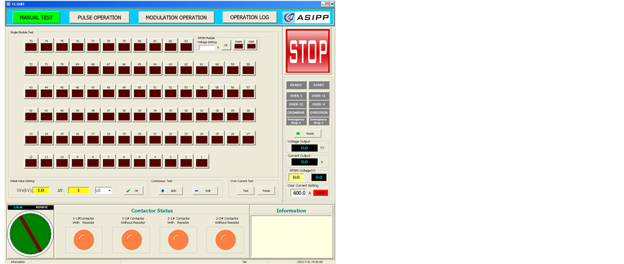
・ Choosing the work mode and setting the operation parameters. The software interfaces of different operation modes are shown in Figure 4, there are 3 modes can be chosen, the manual test mode which is used for debugging the power supply system, the pulse mode and modulation mode are used for the specific experiments.
・ Failure warning. The interface can display different kinds of failure signals and allows the operator to reset the whole power supply system.
・ Emergency stop. The operator can shut down the power supply by clicking the “STOP” button in an emergency to protect the power source and the electron cyclotrons.
3.2. The Logic Controller
The logic controller is used for processing the information of the power source and the load. Its main functions are controlling the switching cabinet, storing the fault signals and shut off the power source in case of emergency. Its program flow chart is shown in Figure 5.
3.3. The Pulse Controller
In order to realize the precise timing control of the PSM modules, we use FPGA as the core controller to make up pulse generator which controls the switch-on and switch-off of PSM module [11] . The minimum timing interval is 1 uS, and the interval setting value can change from 1 uS to 1 S. We will adopt EP1C6Q240C8N of company ALTERA with 100 MHz crystal oscillator, so the maximum delay time of digital synchronous output is 10 nS, and it can meet the requirement of 1us minimum timing.
The basic structure of FPGA controller is shown as Figure 6. It mainly contains 100DI/100DO/4AI/4AO.
Digital input is used to receive status signals and fault signals. Digital output is used to control switch-on and switch-off of PSM modules according to the predetermined parameters inputted through the HMI interface. It can also turn off all the PSM modules quickly when the any failure occurs. Analog input can collect output voltage and output current. The chip ADS7865 with 10 bit is adopted to realize analog-digital converter.
3.4. The Interface Conversion Circuit
In order to realize the isolation of high voltage and to improve anti-EMI capability of the control system, the fiber optic is adopted. So designing an interface chassis for the electrical and optical signals converting is necessary, and the impedance match between the interface board and the FPGA board must be considered.
 (a)
(a) (b)
(b)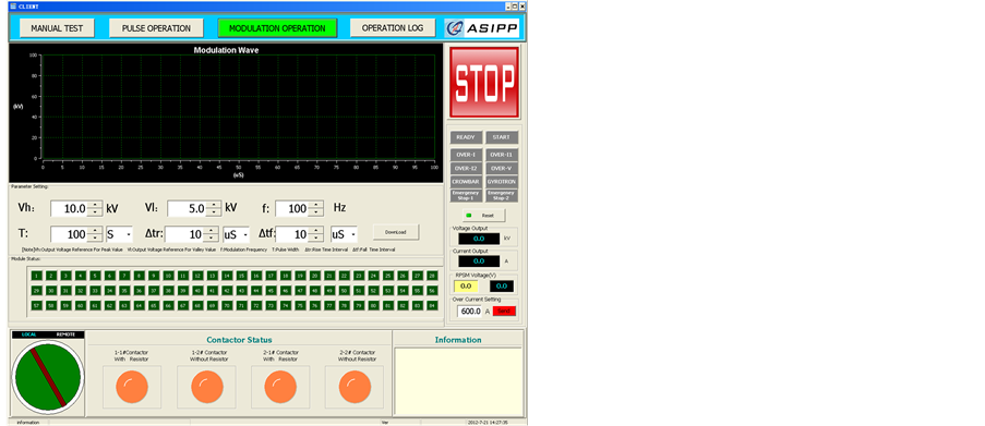 (c)
(c)
Figure 4. Software interfaces of different operation modes. (a) Manual test; (b) Pulse operation; (c) Modulation operation.
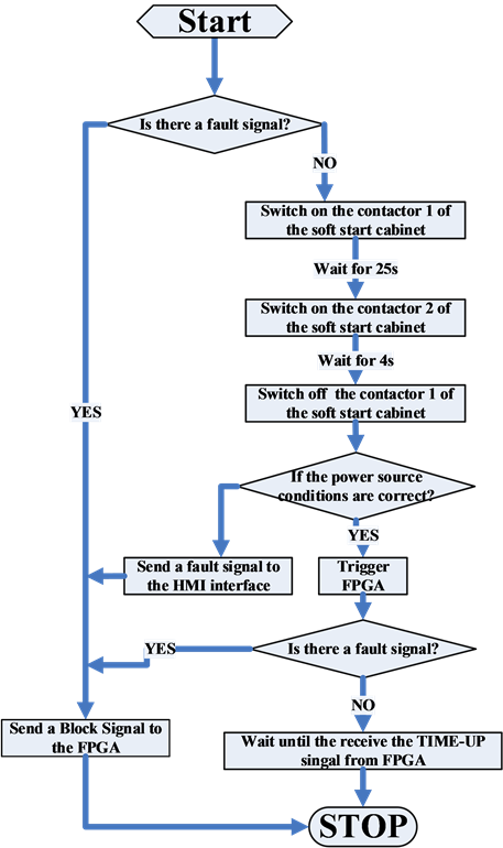
Figure 5. Program flow chart of logic controller.
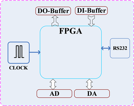
Figure 6. Diagram of FPGA control board.
The digital input signals are 0VDC and 5VDC for the FPGA. Digital input port of FPGA is defined as high impedance, so the input current is very low and less than 10 mA.
The digital output signals are also 0VDC and 5VDC for the FPGA, and every channel can supply a max output current of 10 mA for the interface board electrical input.
The analog input signals are 0VDC to 10VDC for the FPGA, and for the impedance match an emitter follower is designed to connect the interface board analog output and FPGA analog input. It will not have special output current requirements of the interface board.
The analog output signals are also from 0VDC to 10VDC for the FPGA, and for the impedance match an emitter follower is designed to connect the interface board analog input and FPGA analog output. It will not have special output current requirements of the FPGA analog output.
The analog input and output signals will utilize the voltage-frequency converters, which will firstly transform voltage electrical signal to frequency electrical signal and then be transmitted by fiber optic through an electric-optic converter, and at the receiver the frequency-voltage converter will be adopted to transform the optic signal into voltage electrical signal.
3.5. Voltage & Current Detector
To make sure the PSM power source runs safely and smoothly, the multi-protection is applied which mainly includes 1 over-voltage protection, 2 over-current protections, 1 crowbar latch-up protection and 1 gyrotron fault protection. The signals of crowbar latch-up protection and gyrotron fault protection are from the external devices, and the over-voltage and over-current signals are sent by the voltage & current detector which is shown in Figure 7.
The detector can detect the values of output current and output voltage which are shown on the front panel. It can also compare the measured values with the corresponding thresholds. When any measured value exceeds the threshold, it will send a fault signal to the core calculation part to shut down the power source. The process is shown in Figure 8.

Figure 7. Voltage & current detector.

Figure 8. Protection process of voltage & current detector.
4. The Experimental Results and Discussions
The control system in this paper is tested on the −60 KV/50A PSM power source whose main performance parameters are shown in Table 1.
4.1. Manual Mode Test
Firstly, set the output voltage to 15 kV, when turn on the PSM power supply, the output voltage rise to the set value rapidly, then the operate turn on/off the PSM modules optionally, the output voltage and output current waveforms are shown in Figure 9.
4.2. Pulse Mode Test
・ Turn on the PSM modules in sequence at a different time intervals.
・ Set the output voltage 35 KV and the FPGA calculates that 43 modules should be turned on. From Figure 10, we can see that when set the time intervals ∆tr to 50 us, the rising time of output voltage is 2150 us, when set the time intervals ∆tr to 1us, the rising time of output voltage is 43 us.
・ Change the working time of the PSM power source.
Set different parameters of working time, the curves of output voltage and output current changes (as shown in Figure 11).
4.3. Modulation Mode Test
Set the duty ratio 50%, the output voltage 35 KV. By changing the parameter of frequency, we can get different curves of output current and output voltage. The experimental results are shown in Figure 12.
4.4. Protection Test
As shown in Figure 13, the control system can shut off the PSM power source on a simulated short circuit fault.

Table 1. Main performance parameters of the −60 KV/50A PSM power source.

Figure 9. The experimental result of manual mode.
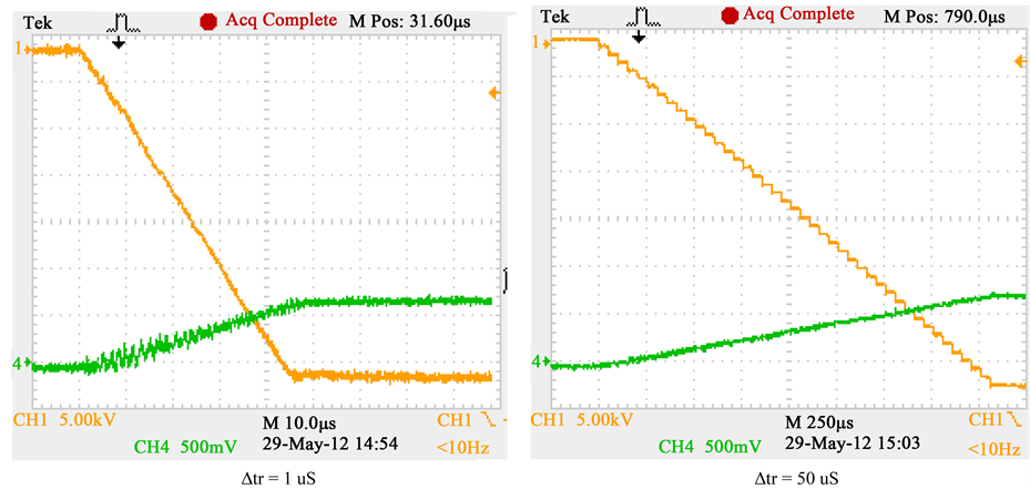
Figure 10. The output current and output voltage of different start-up time intervals.

Figure 11. The output voltage and output current of different working time.
4.5. Results Discussion
・ As shown in Figure 9, each PSM module can be controlled separately, the manual mode is very helpful for the operator to test and debug the PSM power source.
・ From Figure 10, when set the time intervals ∆tr to 1us, the rising time of output voltage is 43 us when 43 PSM modules need to be turned on. Thus the control system’s time precision of interval satisfies the 1 us requirement.
・ As is evident from Figure 10 and Figure 11, under pulse mode, the operator can set different time interval and working time of PSM power supply, therefore, the control system can implement the pulse mode. Also from Figure 12, the duty ratio, the frequency and the output voltage can be set, so it can be proved that the control system can implement the Modulation mode.
・ As can be seen from Figure 13, the output current rises to maximum value in 2 us and then drop to 0 slowly which means that the PSM power supply is turned off in 2 us when short circuit fault occurs. The parameter satisfies the requirement that the control system can shut off the power source in 10 us in an emergence.

Figure 12. The output voltage and output current of different frequency.

Figure 13. The output voltage and output current of different frequency.
5. Conclusions
Highly demanded power source adds the difficulty to design and build its control system. In this paper, the method of designing the control system of PSM power supply is introduced based on its practical requirements. A new structure divides the core calculation unit into 2 single parts: the logic controller and the pulse controller are proposed to realize the high demand of turning on or turning off the PSM modules in sequence at a time interval of a minimum and accurate 1us, which is a main innovation point of this paper. Then each part of the control system is introduced specifically. At last, the experimental results are presented which indicate the control system, meet all its requirements and can be applied to ECRH system.
Component heads identify the different components of your paper and are not topically subordinate to each other. Examples include Acknowledgements and References and, for these, the correct style to use is “Heading 5”. Use “figure caption” for your Figure captions, and “table head” for your table title. Run-in heads, such as “Abstract”, will require you to apply a style (in this case, non-italic) in addition to the style provided by the drop down menu to differentiate the head from the text.
Text heads organize the topics on a relational, hierarchical basis. For example, the paper title is the primary text head because all subsequent material relates and elaborates on this one topic. If there are two or moresub-topics, the next level head should be used and, conversely, if there are notat least two sub-topics, then no subheads should be introduced. Styles named “Heading 1”, “Heading 2”, “Heading 3”, and “Heading 4” are prescribed.
Cite this paper
Jian Zhang,Xu Hao,Wei Wei,Yiyun Huang, (2016) The Design of PSM-Based ECRH Power Supply Control System. Journal of Power and Energy Engineering,04,91-102. doi: 10.4236/jpee.2016.44009
References
- 1. Choi, D.I., Lee, G.S., Kim, J., et al. (1997) The KSTAR Tokamak. 17th IEEE/NPSS Symposium, San Diego, 6-10 October 1997, 215-220.
- 2. Xu, W. and Xuan, W. (2014) The High Voltage Power Supply Based on Pulse Step Modulation for Auxiliary Heating System on Fusion Device. IEEE International Conference on High-Power Particle Beams (BEAMS), Washington DC, 25-29 May 2014, 1-1.
- 3. Zhang, M. and Xuan, W.M. (2014) A Pulse Step Modulator High-Voltage Power Supply for Auxiliary Heating System on the HL-2A Tokamak. IEEE Transactions on Plasma Science, 42, 1425-1429.
- 4. Alves, D., Coelho, R., Neto, A.C., Smith, P., Valcarcel, D.F., Card, P., Felton, R., Lomas, P.J., McCullen, P. and JET EFDA Contributors (2015) A Flexible System for the Control of External Magnetic Perturbations in the JET Tokamak. IEEE Transactions on Plasma Science, 43, 650-664.
- 5. Yao, L.Y., Wang, Y.Q., Mao, X.H., Wang, Y.L. and Li, Q. (2012) A Fully Digital Controller of High-Voltage Power Supply for ECRH System on HL-2A. IEEE Transactions on Plasma Science, 40, 793-797.
- 6. Yang, Z.J., Zhuang, G., Hu, X.W., Zhang, M. and Qiu, S.S. (2009) The J-TEXT Tokamak Control System. Proceedings of International Conference on Electronic Computer Technology, Piscataway, 20-22 February 2009, 654-658.
- 7. Luo, J.R., Wang, H.Z., Ji, Z.S., Zhu, L., Wang, F. and Shu, Y.T. (2002) The Distributed Control and Data System in HT-7 Tokamak. IEEE Transactions on Nuclear Science, 49, 496-500.
- 8. Cool, R., Chaudron, G.-A., Demers, Y., Guay, J.-M., Larose, D., Magne, R., Trudel, C., Decoste, R., Desroches, D., Dube, A., Robert, A. and Vachon, L. (1997) Control and Protection System for the 110 GHz ECRH System on the TdeV Tokamak. Proceedings of 17th IEEE/NPSS Symposium, San Diego, 6-10 October 1997, 527-530.
- 9. Cragon, H.G. (1980) The Elements of Single-Chip Microcomputer Architecture. Computer, 13, 27-41.
- 10. Tang, P.C., Lu, S.S. and Wu, Y.C. (1982) Design and Implementation of a Fully Digital DC Servo System Based on a Single-Chip Microcomputer. IEEE Transactions on Industrial Electronics, IE-29, 295-298.
- 11. Rodrigues, A.P., Pereira, L., Madeira, T.I., Amorim, P., Varandas, C.A.F. and Duval, B. (2006) Real-Time Multi-DSP Based VME System for Feedback Control on the TCV Tokamak. IEEE Transactions on Nuclear Science, 53, 845-848.