Journal of Surface Engineered Materials and Advanced Technology
Vol.1 No.3(2011), Article ID:7991,8 pages DOI:10.4236/jsemat.2011.13021
Surface and Bulk Defects in Cr-Mn Iron Alloy Cast in Metal and Sand Moulds: Characterization by Positron Annihilation Techniques
![]()
1Materials Technology Division, Central Power Research Institute, Bangalore, India; 2Department of Studies in Physics, University of Mysore, Mysore, India; 3Radiochemistry Division, Bhabha Atomic Research Centre, Mumbai, India; 4Department of Materials Engineering, Indian Institute of Science, Bangalore, India.
Email: *crang1@rediffmail.com
Received August 17th, 2011; revised September 2nd, 2011; accepted September 28th, 2011.
Keywords: Cr-Mn Cast Iron, Heat Treatment, Positron Lifetime Spectroscopy, Slow Positron Beam Analysis
ABSTRACT
High chromium (Cr: 16% - 19%) iron alloy with 5% and 10% manganese (Mn) fabricated in metal and sand moulds by induction melting technique were investigated for defects microstructure both in the as-cast and heat treated conditions. Non-destructive techniques namely Positron Lifetime Spectroscopy and slow positron Doppler Broadening studies were employed to characterize the defects in the bulk as well as surface of the alloy and their influence of metallurgical parameters. The Positron Lifetime Spectroscopy data reveals that the defect concentration is higher for sand mould alloy samples compared to metal mould ones. The reasons for fewer defects in metal mould are attributed to faster heat transfer in the metal mould. Further, heat treatment yielded spherodization of carbides in the matrix resulting in reduced defects concentration. The S-parameter profiles from Doppler Broadening studies suggest defect concentration at the surface is less in 5% Manganese and near absence of any modification of defect structure following heat treatment in 10% Manganese sample closer to surface.
1. Introduction
Metal wastage occurs in ferrous materials on account of wear and erosion in certain critical parts of thermal power generators like coal and ash handling equipments, pressure parts etc., This is usually ascribed to high percentage of alpha quartz present in the coal [1,2] and is responsible for wear damage. Therefore, it is always desired to enhance the lifespan of such parts to withstand wear & erosion [3]. Several attempts have been made in the past two or three decades to minimize wear and erosion. From these studies it is understood that the material found to be a promising wear resistant is high chromium (Cr) iron [4] since it contains hard carbides (M7C3) in a martensitic matrix, but fails to withstand sudden load/ shock. To improve the impact resistance, manganese (Mn) is added since Mn is an austenite stabilizing agent. Earlier works [5,6] show that Mn content up to 4.4% in chromium irons has yielded higher toughness compared to Mn free irons. Unfortunately there is no literature on the use of Mn beyond 4.4% in such alloy system. Hence the present work focuses on the use of Mn at 5% & 10% in Cr (16% - 19%) rich iron, cast in metal and sand moulds to study the defect structure in the as-cast and heat treated conditions. The slow positron beam analysis (DBAR) and conventional positron lifetime analysis (PLS) have been used for the first time to study the defect morphology in terms of defect concentration both at the surface and bulk to understand the influence of manganese addition under change of mould and heat treatment of the samples which has a direct bearing on erosion of particles from the surface and its connection to bulk material. There are only few studies using other techniques reported on this particular iron system [3-6] which is one of the most sought after materials in thermal power generators and the like.
Positron annihilation spectroscopic studies evolving experiments, namely, slow positron beam based Doppler broadening of annihilation radiation (DBAR) measurements and conventional positron lifetime measurements (PLS) are outlined in the following; Slow positron beam used for the present study consists of a Ultra high vacuum compatible sealed 22Na radioisotope as the positron source. Positrons emitted from the source were thermalized by W single crystal floated at 200 V (moderator), which has negative work function for the positrons. The thermalized positrons diffuse to the surface of moderator, which are extracted by an einzel lens to the solenoid. Positrons travel in spiral motion under the magnetic field in the solenoid, which act as a velocity filter to enhance the monochromatic nature of the positron beam. Positrons in the form of beam fall on the sample in the target chamber, where a magnetic field is maintained by two Helmholtz coils. The sample holder can be floated from 0 V to 50 kV which can accelerate positrons to the required energy. Doppler broadening spectroscopy measurement as a function of implantation depth of positron beam has been evolved as a good technique for depth profile of defects at the surface of system, because the fraction of implanted positrons annihilating in two gamma photons depends upon the size and distribution of defects and electron density at the site of positron [4]. In the conventional positron lifetime technique, positrons from a 22Na source are injected into the system under investigation and they thermalize very rapidly. Subsequently, they annihilate with free electrons of the medium labeled as free annihilation, or if get trapped in a defect of the system and then annihilates, is usually called trapped state annihilation [7,8]. Since positrons localize in defects and annihilate [7,8], their lifetime and intensity provide information on the nature of defects and their concentration in the bulk and as such it has been established as a novel tool for studying the microstructural behavior of metals, alloys and a wide variety of materials for more than four decades [8].
The bulk positron lifetime spectroscopy technique has been used to establish a good correlation between fatigue life ratios and PLS parameters [4] in stainless steels to predict early fatigue damage detection. The work related to correlation of erosion behavior with surface defect characteristics in Cr-Mn alloy systems does not seem to exist in literature. Hence, the usefulness of slow positron beam studies combined with PLS has been used to understand the correlation of surface defects with the microstructure in 5% and 10% Cr-Mn iron produced in sand and metal moulds in this work.
2. Experimental
The metal & sand molded test samples of size 75 × 25 × 6 mm3 were given austenitization soak at 960˚C for 2 hours followed by oil quenching and then finally tempering at 200˚C for 30 min with air cooling to room temperature. The as-cast and heat treated samples were subjected to defect characterization using slow positron beam analysis (DBAR) spectroscopy and conventional positron lifetime spectroscopy (PLS). The details in respect of the melting and casting procedures of Cr-Mn alloy system under investigation are covered in detail in our earlier published work [6].
2.1. Slow Positron Doppler Broadening Annihilation Radiation Measurement (DBAR)
DBAR was carried out in Cr-Fe alloy prepared as described in metal and sand moulds and in as cast and heat treated conditions using the slow positron beam facility at Radiochemistry Division, Bhabha Atomic Research Centre, India. The present beam has three components interconnected under high vacuum viz. (i) slow positron production (Source and moderator), (ii) focusing and transport (Einzel lens and magnetic transport) and (iii) acceleration of positrons at the target. Positrons emitted from a sealed 22Na source are moderated by 1 μ thick tungsten single crystal. The thermalized positrons come to the surface as tungsten has negative work function for positrons. The positrons extracted from the moderator are focused by the Einzel lens and are guided towards the sample through a magnetically guided assembly (90 degree bent solenoid and two Helmholtz coils, respecttively). The positron energy is varied by floating the sample at different voltages. The energy range of the positron beam is 200 eV - 50 keV. Doppler broadened annihilation radiation measurements were carried out using an HPGe detector having resolution of 1.7 keV at 1332 keV photo peak of 60Co. A spectrum with 106 counts was acquired at each energy. The shape parameter, namely, S-parameter defined as the ratio of the number of counts falling in a fixed energy window (± 1 keV) centered at 511 keV to the total number of counts under the Gaussian peak, was evaluated. The S-parameter at the surface and in bulk was determined using computer program VEPFIT [5]. The variation in the S-parameter as a function of depth gives the defect depth profile in the sample. Further details of this experiment and analysis can be found from Ref [9,10].
2.2. Positron Lifetime Spectroscopy (PLS)
Positron annihilation lifetime spectra were recorded at room temperatures in the Cr-Mn iron system using a fastfast coincidence system with BaF2 scintillators coupled with photo multiplier tubes and quartz window as detectors in about 1 to 2 hours. Three Gaussian time resolution functions were used in the lifetime analysis for fast and good convergence keeping the net resolution function around 220 × 10–12 s i.e. (220 ps). The details of the experimental procedure and analysis can be found in our earlier work [11]. All spectra were analyzed into two lifetime components with the help of the computer program PATFIT-88 [12] with proper source and background corrections. The analysis gives two lifetimes τ1 and τ2 with respective intensities I1 and I2. In the present analysis, τ1 is fixed at 107 ps which correspond to lifetime of positrons in Fe and in the present systems Fe is the matrix. The fixed analysis will not suppress any information since the free annihilation lifetime does not provide any material information. The trapping rate (k) which is a measure of the defect concentration in the system is estimated by adopting the two state trapping model [7,8]. The parameters of the trapping model are the positron lifetimes in the free and trapped states with intensities I1 and I2. The rate at which transitions from the delocalized states to the localized ones happen is the trapping rate. This transition rate (positron trapping rate) k is proportional to the concentration of the defects. The positron annihilation lifetime in bulk (τb) and in defect (τd) can be determined from [7,8]
 (1)
(1)
and λd = 1/τd = τ2−1, where λb and λd are the decay rate of positron from bulk and defect respectively. The positron mean lifetime, τm can be calculated using the formula [7,8]
 (2)
(2)
The τd is always larger than τb for open-volume defects, such as vacancies, dislocations due to the decreased electron density in the defect site compared to the bulk material and hence traps positrons.
Then the trapping rate k is calculated from the equation below
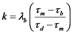 (3)
(3)
Also, k = µCd, where Cd is the defect concentration and the proportionality constant μ is the specific trapping coefficient and a value of 1.1 × 10¹⁵/sec is used in the calculation of Cd with appropriate weight fraction taken into account for the alloy system of the present study.
3. Results and Discussion
The positron annihilation lifetime and intensity are sensitive to microstructural changes due to lattice defects, such as vacancies and dislocations caused either by deformation or processing or addition of substitutional elements. They are considered to be effective non destructive evaluation parameters of the damage or microstructural changes brought about to the system under study. If lattice defects exist in materials, these defects represent regions of low electron density and become negatively charged. This in turn causes positively charged positrons to be attracted to the lattice defects or in other words, positrons get trapped in to such defects and then annihilates from these sites. When positrons annihilate from these defects, the lifetime will be larger than the bulk lifetime. Therefore, as the number of defects increases, the number of positrons trapped in such defects also increases and the intensity of trapped lifetime also increases [7,8,13].
Positron lifetime data from PLS for both as-cast (AC) and heat treated (HT) conditions are shown in Tables 1 and 2. The evaluated S-parameter, an index of defect concentration, and the diffusion length of positrons in respective samples are given in Table 3. The sample designation followed in the Tables is as follows: first numeral (% Mn) followed by a letter (mould type) and lastly a number (section size). Hence, for example, 5% Mn bearing 24 mm sized metal mould sample is designated as 5M24.
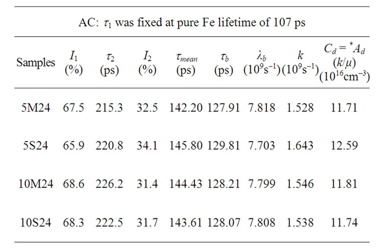
Table 1. Positron Lifetime results for Cr-Mn iron as-cast (AC) samples.

Table 2. Positron Lifetime results for Cr-Mn iron heat treated (HT) samples.

Table 3. VEPFIT slow positron beam DBAR data of Cr-Mn iron samples.
3.1. Influence of Mould type of As-Cast (AC) Samples on PLS Parameters
Considering the positron lifetime data, the mean range of positrons in the Cr-Mn iron systems for 540 keV has been found to be 32.93 µm. With this energy the positrons are expected to probe only the bulk of the system. It is known that the defect profile at the surface is not necessarily the same as that of the bulk; however, the defect profile of the bulk influences the surface properties. This issue has been reported from the surface studies carried out in various metals and semiconductors using slow positron beams [14]. In the present study, we have used both PLS and slow positron beam studies to characterize separately the defects at the bulk and the surface respectively. The lifetime in the present samples in the absence of defects should be in the range 99 - 107 ps. Further, the theoretical estimate of the expected defect lifetime for these systems assuming mono-vacancy type defects should be about 186 ps. But the second lifetime measured for the present alloy systems is in the range 197 - 220 ps which is higher and indicates that there are defects other than mono vacancy present in the sample which might have evolved in the Cr-Mn-Fe system during the solidification process in both metal and sand moulds. Although, the mean range of positrons in all these systems is the same, their defect lifetime show variation with respect to the mould variety used as explained below. For the metal and sand mould employed, the heat transfer process appears to be different in each case; a transformation in the microstructure takes place as a result of varied cooling rates prevailed in the moulds. Further, it is observed that a consistent reduction in mean lifetime for samples after heat treatment (Tables 1 and 2) indicates that some of the defects are indeed annealed out. As the fraction of positrons probing the single interface is negligible due to the mean positron diffusion length of few hundred nanometers, very little trapping is expected from the interface. These facts indicate that most of the positrons are getting annihilated in the bulk state as seen from I1 and I2 values given in Tables 1 and 2.
The lower positron lifetime and less number of defects exhibited by 5M24 (Figures 1 and 3) indicates the fact that metal mould produces less number of defects compared to 5S24. Similarly, there is a marginal variation in lifetime and defects concentration Cd in 10M24 compared to 10S24 (Figures 2 and 4). In an earlier published work of the author on the same system [15,16], it was reported that the erosion volume loss is lower at all impact angles and hardness is higher for the 5% Mn and 10% Mn bearing metal mould samples compared to the sand mould ones. More clearly, for metal mould samples, because of shorter positron lifetime and less defect concentration, higher hardness and low erosion loss were observed compared to sand mould samples.
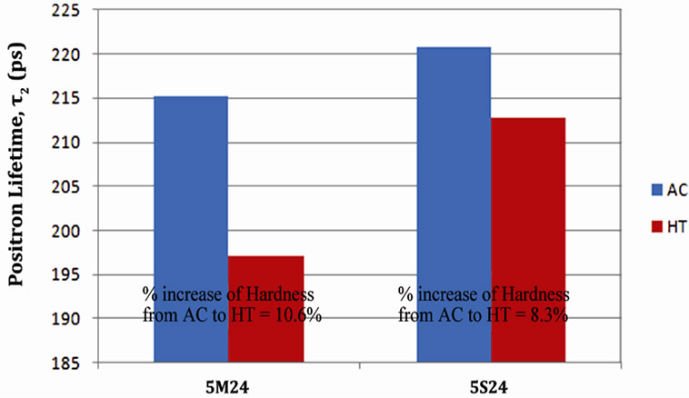
Figure 1. Plot of positron lifetime t2 for 5M24 and 5S24 samples.

Figure 2. Plot of positron lifetime t2 for 10M24 and 10S24 samples.
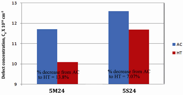
Figure 3. Plot of defect concentration Cd for 5M24 and 5S24 samples.

Figure 4. Plot of defect concentration Cd for 10M24 and 10S24 samples.
This shows that there is a definite correlation between defect structure from PLS, hardness and erosion results observed for these samples. These data trends have now been explained based on the heat transfer characteristics obtained during the solidification process on account of mould variety adopted. The heat transfer coefficients may be calculated using the well known equation [17] given below.
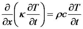 (4)
(4)
where k is the thermal conductivity, ρ is density and c is specific heat.
When the effect of solidification rate on the erosion and PLS parameters is to be looked into, Equation (5) given below is used to calculate the heat transfer rate during melting and casting taking in to account the thermal conductivity of the mould type used. This equation is obtained by integrating the Equation (4) with appropriate boundary conditions [17].
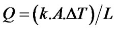 (5)
(5)
Here Q is Heat transfer rate, A is the cross sectional area, L is the overall thickness of the casting, and DT is temperature difference during solidification.
It is noted that the solidification rate prevailed in the metal mould is higher than in sand mould in view of higher thermal conductivity (k) and lower specific heat (c) prevailed in the metal (k = 52 W/m∙k) mould compared to sand (k = 0.325 W/m∙k) mould which has lower k and higher c. Further, the heat transfer rate is more in the metal mould compared to sand mould counterpart as it is directly proportional to “k” the thermal conductivity. Hence, the heat transfer coefficient will also be higher in the metal mould than in sand mould. No attempt has been made in this work to measure the temperatures at the mould wall as well on the casting periphery. These factors give credence to the present data trends thus emphasizing the fact that the metal mould samples have smaller sized carbides and less defect concentrations compared to the sand mould counterparts.
3.2. Effect of Mould Variety on PLS Parameters in the Heat Treated (HT) Condition
From the PLS data, it is seen that the defect size and its concentration (Cd) are higher for as-cast samples irrespective of Mn content compared to the corresponding heat treated samples. Following heat treatment in 5M24 sample, the defect concentration Cd decreases by 13.8% while it is 7.07% decrease in 5S24 sample (Figure 3). In case of 10M24, upon heat treatment, the defect concentration Cd decreases by 3.73% while 10S24 sample showed a decrease by 5.96% (Figure 4). These observations are attributed to annealing out of some defects and also resulting in smaller size defects. Therefore, the changes in defect concentration correlate well with the improved erosion behavior and hardness characteristics of Cr-Mn iron systems reported earlier on the high chromium irons [18] that the erosion process is dominated by the matrix removal with carbide particles not getting damaged. Interestingly, from the earlier work of the authors [15,16], it was observed that, following heat treatment, the erosion data showed higher volume loss at all impact angles and lower hardness for 5S24 compared to 5M24 samples and the same was the trend observed in the case of 10M24 and 10S24 samples. Therefore, we can see that increased defect concentration resulted in lower hardness and higher erosion loss in the as cast samples and heat treated samples of 5S24 and 10S24 which can be attributed to longer time available for the diffusion of molten material and the evolution of bigger size carbides in the sand mould samples and vice versa is true for metal mould samples. In other words, the globular type of carbides were formed in faster cooling conditions prevailing in metal mould casting. This further verifies the correlation of the positron data with the erosion and hardness results observed by the authors.
3.3. Surface Defect Characterization Using the Slow Positron Beam Analysis (DBAR)
The basis of DBAR spectroscopy is due to the relative velocities of positron and electron pair just prior to annihilation; the energy deviation from 511 keV is dominated by the moment of the electrons. Since the electron momentum distribution at a defect site is the characteristic of that defect, the DBAR energy lines-shape is in fact a “fingerprint” of the defect structure in material. Thus, by monitoring changes in the DBAR line-shape parameter, it is possible to track changes in the defect types and/or defect concentrations [19]. If the energy of the incident positron can be varied, the depth profile of the defects can be understood from DBAR. The variation in positron annihilation line-shape parameter S as a function of incident positron energy and the mean implantation depth of the positron beam is shown in Figure 5. The mean implantation depth áZñ of mono-energetic positron beam having incident energy E in a material with density r (gm/cc) is determined using the following equation [20]
 (6)
(6)
where, áZñ is expressed in nm and E in KeV.
The positrons implanted in the sample have three paths to annihilate: 1) annihilation in the vacancy-free bulk; Sbulk is a characteristic parameter for the material; 2) trapping by vacancy-type defects and annihilation there, leading to a value Svac higher than Sbulk and 3) diffusion to the sample surface, giving a value Ssurf lower than Sbulk.
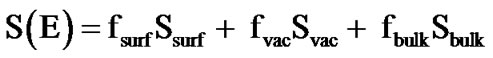 (7)
(7)
where fsurf, fvac and fbulk are the fraction of positrons annihilating at the surface, in the vacancy-type defects, and in the bulk.
S-parameter characterizes the positrons that annihilate with low momentum electrons, mostly valence electrons and it is sensitive to open volume defects. Therefore, an increase in S-parameter can be taken as an indication of increased vacancy defects [21-23]. For low energy positrons, the changes in the S parameter as a function of positron energy provides the defects at the surface and we towards the bulk as the positron energy are increased. The S-parameter profile of 5% Mn concentration is seen to be different from other two 10% Mn [as-cast (AC) and heat treated (HT)] samples (Figure 5). The surface, as
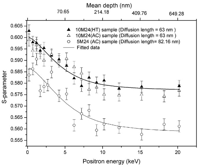
Figure 5. The variation in S-parameter as a function of incident positron energy and the mean implantation depth of the positron beam.
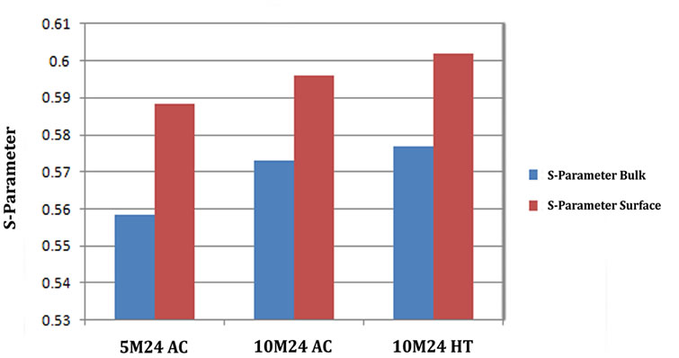
Figure 6. Plot of S-Parameter for 5M24AC, 10M24 AC and 10M24 HT samples.

Figure 7. Plot of Diffusion length for 5M24 AC, 10M24 AC and 10M24 HT samples.
well as the bulk values of the S-parameter (Sbulk and Ssurf) in 5% Mn sample is seen to be lower than the other two 10% Mn samples (Figure 6). It indicates that the defect concentration increases with the increase in Mn percentage both at the surface as well as in bulk. The diffusion length in 5% Mn sample is also higher compared to 10% Mn samples (Figure 7), suggesting a low concentration of defects in 5% Mn sample. However, the profiles of S-parameter among the two 10% Mn (AC and HT) samples are almost identical indicating near absence of any modification of defect structure near the surface following heat treatment in 10% Mn sample.
4. Conclusions
It is inferred from the above study that:
1) Defect size and their concentration are found to be less in 5M24 metal mould sample compared to sand moulded one and this further improves with heat treatment according to PLS data. 10% Mn will not change the defects concentration very much.
2) Heat treatment brings out improved microstructural transformation with some defects getting annealed out and hence defect concentration (Cd) has come down.
3) The slow positron beam analysis (DBAR) data reveals that surface, as well as the bulk values of the S-parameter in 5M24 sample is seen to be lower than the two 10M24 samples suggesting less concentration of defects at the surface. Further it is observed that the defect concentration increases slightly with the increase in Mn from 5% to 10% at the surface.
4) The PLS and DBAR techniques can be effectively used to study the defect structure in the bulk and surface of an alloy material which is very important information while designing materials with little erosion volume loss in their final industrial application.
5. Acknowledgements
The authors thank the management of Central Power Research Institute for having accorded permission to publish this paper. The authors wish to acknowledge with thanks Mr. R. K. Kumar & Mr. J. Shankar of MTD, CPRI for their support in conducting the experiments and preparation of the manuscript. One of the authors (Ki-shore) would like to thank CSIR for the award of fellowship under Emeritus Scientist Scheme.
REFERENCES
- P. R. Krishnamoorrthy, S. Seetharamu and P. Sampathkumaran, “Erosion Wear in Thermal Power Plants,” 55th R and D Session of CBI & P, India, July 1999, p. 1.
- J. T. H. Pearce, “Structure and Wear Performance of Abrasion Resistant Chromium White Cast Irons,” AFS Transactions, Vol. 126, 1984, pp. 599-622.
- A. Basak, J. Pening and J. Dellewyns, “Effect of Manganese on Wear Resistant and Impact Strength of 12% Chromium White Cast Iron,” AFS International Cast Metal Journal, 1981, p. 12.
- Y. Kawaguchi and Y. Shirai, “Fatigue Evaluation of Type 316 Stainless Steel Using Positron Annihilation Line Shape Analysis and
 Coincidence Positron Lifetime Measurement,” Journal of Nuclear Science and Technology, Vol. 39, No. 10, 2002, pp. 1033-1040. doi:10.3327/jnst.39.1033
 - A. Van Veen, H. Schut, M. Clement, J. M. M. de Nijs, A. Kruseman and M. R. IJpma, “VEPFIT Applied to Depth Profiling Problems,” Applied Surface Science, Vol. 85, No. 2, 1995, pp. 216-224. doi:10.1016/0169-4332(94)00334-3
- P. Sampathkumaran, S. Seetharamu and Kishore, “Erosion and Abrasion Characteristics of High Manganese Chromium Irons,” Wear, Vol. 259, No. 11-6, 2005, pp. 70-77. doi:10.1016/j.wear.2005.03.001
- P. Hautojarvi, “Positrons in Solids,” Springer-Verlag, Berlin, 1979.
- W. Brandt and A. Dupasquier, “Positron Solid State Physics,” North-Holland, Amsterdam, 1983.
- P. K. Pujari, D. Sen, G. Amarendra, S. Abhaya, A. K. Pandey, D. Dutta and S. Mazumder, “Study of Pore Structure in Grafted Polymer Membranes Using Slow Positron Beam and Small-Angle X-ray Scattering Techniques,” Nuclear Instruments Methods Physics Research B, Vol. 254, No. 2, 2007, pp. 278-282. doi:10.1016/j.nimb.2006.11.052
- M. Tashiro, Y. Honda, T. Yamaguchi, P. K. Pujari, N. Kimura, T. Kozawa, G. Isoyama and S. Tagawa, “Development of a short-Pulsed Slow Positron Beam for Application to Polymer Films,” Radiation Physics Chemistry, Vol. 60, No. 4-5, 2001, pp. 529-533. doi:10.1016/S0969-806X(00)00403-5
- H. B. Ravikumar, C. Ranganathaiah, G. N. Kumaraswamy and Siddaramaiah, “Influence of Free Volume on the Mechanical Properties of Epoxy/Poly (Methylmeth-Acrylate) Blends,” Journal of Material Science, Vol. 40, No. 24, 2005, pp. 6523-6527. doi:10.1007/s10853-005-1707-3
- P. Kirkegaard, N. J. Pederson and M. Eldrup, “PATFIT- 88: Riso National Laboratory Report PM-2724,” Riso National Laboratory, Riso, 1989.
- M. J. Puska, and R. M. Nieminen, “Theory of Positrons in Solids and on Solid Surfaces,” Reviews of modern Physics, Vol. 66, No. 3, 1994, pp.841-897. doi:10.1103/RevModPhys.66.841
- S. Shikata, S. Fujii, L. Wei and S. Tanigawa, “Effect of Annealing Method on Vacancy Type Defects in Si Implanted GaAs Studies by a Slow Positron Beam,” Journal of Applied Physics, Vol. 31, 1992, pp. 732-736. doi:10.1143/JJAP.31.732
- P. Sampathkumaran, C. Ranganathaiah, S. Seetharamu and Kishore, “Effect of Increased Manganese Addition and Mould Type on the Slurry Erosion Characteristics of Cr-Mn Iron Systems,” Bulletin Materials Science, Vol. 31, No. 7, 2008, pp. 1001-1006. doi:10.1007/s12034-008-0157-3
- S. Seetharamu, P. Sampathkumaran and R. K. Kumar, “Erosion Resistant of Permanent Moulded High Chromium Iron,” Wear, Vol. 267, No. 1, 1995, pp. 159-167. doi:10.1016/0043-1648(95)07173-3
- S. N. Kulkarni and K. Radhakrishna, “Evaluation of MetalMould Interfacial Heat Transfer during the Solidification of Aluminium –4.5% Copper Alloy Castings Cast in CO2- Sand Moulds,” Materials Science, Vol. 23, No. 3, 2005, pp. 821-838.
- E. Raask, “Erosion Wear in Coal Utilization,” Hemisphere Publishing Corporation, New York, 1988.
- R. Vaidyanathan, J. P. Schaffer and B. Thanaboonsombut, “A Doppler Positron Annihilation Spectroscopy Study of Magnetically Induced Recovery in Nickel,” Atlanta, Easton, 1993.
- P. J. Schultz and K. G. Lynn, “Interaction of Positron beams with Surfaces, Thin Films, and Interfaces,” Reviews of Modern Physics, Vol. 60, No. 3, 1989, pp. 701-779. doi:10.1103/RevModPhys.60.701
- M. Zhang, R. Scholz, H. Weng and C. Lin, “Defects and Voids in He
 Implanted Si Studied by Slow Positron Annihilation and Transmission Electron Microscopy,” Applied Physics A, Vol. 66, No. 5, 1998, pp. 521-525. doi:10.1007/s003390050707
 - C. He, T. Suzuki, E. Hamada, H. Kobayashi, K. Kondo, V. P. Shantarovich and Y. Ito, “Characterization of Polymer Films Using a Slow Positron Beam,” Materials Research Innovation, Vol. 7, No. 1, 2003, pp. 37-41.
- Y. C. Jean, R. Zhang, H. Cao, J.-P. Yuan and C.-M. Huang, “Glass Transition of Polystyrene near the Surface Studied by Slow-Positron-Annihilation-Spectro-Scopy,” Physical Reviews B, Vol. 56, No. 14, 1997, pp. 8459-8462. doi:10.1103/PhysRevB.56.R8459