Modern Mechanical Engineering, 2011, 1, 56-68
doi:10.4236/mme.2011.12008 Published Online November 2011 (http://www.SciRP.org/journal/mme)
Copyright © 2011 SciRes. MME
Analysis of Stresses and Deflection of Sun Gear by
Theoretical and ANSYS Method
Yogesh C. Hamand, Vilas Kalamkar
Mechanical Department, Sardar Patel College of Engineering, Mumbai, India
E-mail: yogeshhamand@rediffmail.com, vilaskalamkar@gmail.com
Received September 30, 2011; revised October 25, 2011; accepted November 5, 2011
Abstract
Gearing is one of the most critical components in mechanical power transmission systems. This article ex-
amines the various stresses and deflection developed in sun gear tooth of planetary gearbox which is used in
Grabbing Crane. Article includes checking sun gear wear stresses and bending stresses using IS 4460 equa-
tions. Also calculate various forces acting on gear tooth. In this study, perform the calculation for sun gear
tooth to calculate bending, shear, wear & deflection using theoretical method. 3D model is created of circular
root fillet & trochoidal root fillet of gear tooth for simulation using ProE Wildfire 3. In Pro-E, the geometry
is saved as a file and then it is transferred from Pro-E to ANSYS 10 in IGES format. The results of the 3 D
analyses from ANSYS are compared with the theoretical values. Comparison of ANSYS results in circular
root fillet & trochoidal root fillet also carry out.
Keywords: Bending Stress, Circular Root Fillet, Deflection, Grabbing Crane, Planetary Gearbox, Shear
Stress, Sun Gear, Trochoidal Root Fillet, Wear
1. Introduction
In spite of the number of investigations devoted to gear
research and analysis there still remains to be developed, a
general numerical approach capable of predicting the effects
of variations in gear geometry, shear, wear and bending
stresses. The objective of this work is to use ANSYS to de-
velop theoretical models of the behavior of planetary gears
in mesh, to help to predict the effect of gear tooth stresses
and deflection. The main focus of the current research as
developed here is to develop and to determine appropriate
models of contact elements, to calculate various stresses and
using ANSYS and compare the results with theoretical.
The project work mainly deals with
1) Checking of wear stresses & bending stresses using
IS 4460 equations for sun gear.
2) Force calculations for planetary gear
3) Calculate the values for sun gear tooth for bending,
shear, wear & deflection using theoretical method.
4) Generation of gear tooth profile in Pro-E3.
5) Create 3D model of circular root fillet & trochoidal
root fillet of gear tooth for simulation using Pro-E3.
6) Importing Pro-E model in ANSYS in IGES format.
7) Comparison of the results of the 3D analyses from
ANSYS with the theoretical values.
8) Comparison of ANSYS results in circular root fillet
& trochoidal root fillet.
Shanmugasundaram Sankar, Maasanamuthu Sundar
Raj & Muthusamy Nataraj [1] have introduced Correc-
tive measures are taken to avoid tooth damage by intro-
ducing profile modification in root fillet. Tesfahunegn and
Rosa [2] investigated the influence of the shape of profile
modifications on transmission error, root stress and con-
tact pressure through non linear finite element approach.
Chun-Fang Tsai ,Tsang-Lang Liang & Shyue-Cheng Yang
[3] prepared a complete mathematical model of the pla-
netary gear mechanism with double circular-arc teeth is
developed. Ravichandra Patchigolla and Yesh P. Singh [4]
developed a program using ANSYS Parametric De- sign
Language (APDL) to generate 1, 3 or 5 tooth segment
finite element models of a large spur gear. Faydor L. Lit-
vin, Alfonso Fuentes, Daniele Vecchiato, and Ignacio
Gonzalez-Perez [5] proposed a new types of planetary
and planetary face-gear drives & the new designs are
based on regulating backlash between the gears and mo-
difying the tooth surfaces to improve the design.
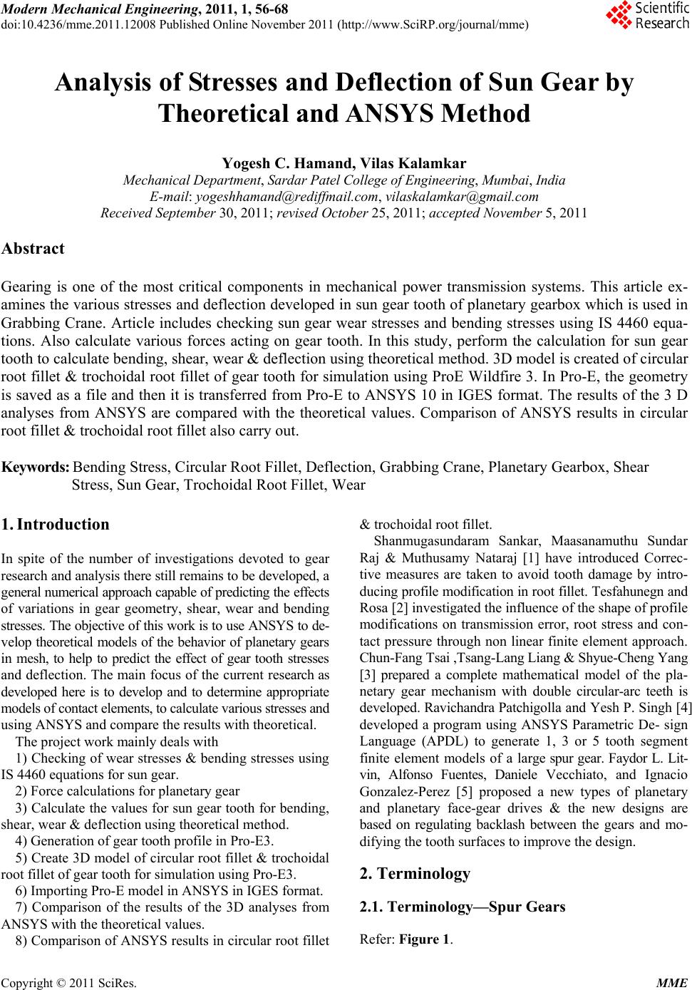
2. Terminology
2.1. Terminology—Spur Gears
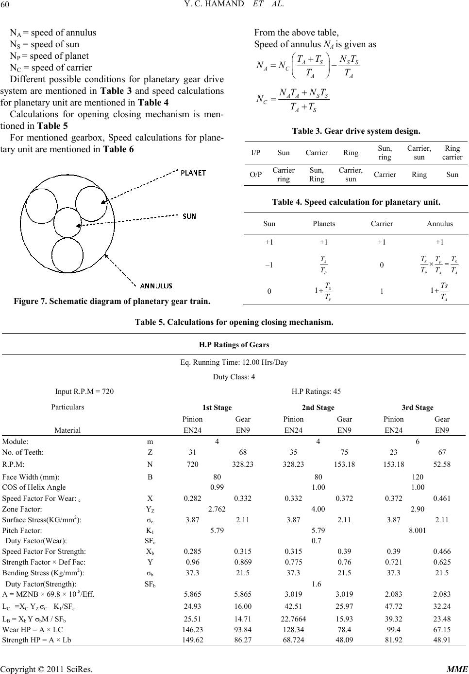
Refer: Figure 1.
57
Y. C. HAMAND ET AL.
Diametral pitch (dp): The number of teeth per one inch
of pitch circle diameter.
Module (m): The length, in mm, of the pitch circle dia-
meter per tooth.
Circular pitch (p): The distance between adjacent teeth
measured along the pitch circle diameter
Addendum (ha): The height of the tooth above the
pitch circle diameter.
Centre distance (a): The distance between the axis of
two gears in mesh.
Circular tooth thickness (Ctt): The width of a tooth
measured along the are at the pitch circle diameter.
Dedendum (hf): The depth of the tooth below the pitch
circle diameter.
Outside diameter (Do): The outside diameter of the gear.
Base Circle diameter (Db): The diameter on which the
involute teeth profile is based.
Pitch circle dia (D): The diameter of the pitch circle.
Pitch point: The point at which the pitch circle diame-
ters of two gears in mesh coincide.
Pitch to back: The distance on a rack between the pitch
Figure 1. Terminology—spur gears.
circle diameter line & the rear face of the rack.
Pressure angle: The angle between the tooth profile at
the pitch circle diameter & a radial line passing through
the same point.
Whole depth: The total depth of the space between ad-
jacent teeth.
2.2. Terminology—Planetary Gear Train
Refer Figures 2 and 3.
Sun: The central gear
Planet Gear: Peripheral gears, of the same size, meshed
with the sun gear and Annulus
Planet carrier: Holds one or more peripheral planet gears,
of the same size, meshed with the sun gear
Ring Gear/Annulus: An outer ring with inward-facing
teeth that mesh with the planet gear or gears
No. of teeth on Gear (Z)
No. of teeth on Sun Gear (S)
No. of teeth on Planet Gear (P)
No. of teeth on Pinion Gear 1 (P1)
Figure 2. Planetary gear train.
Figure 3. Schematic diagram of planetary gear train.
Copyright © 2011 SciRes. MME
Y. C. HAMAND ET AL.
58
No. of teeth on Pinion Gear 2 (P2)
No. of teeth on Ring Gear External (RE)
No. of teeth on Ring Gear Internal (RI)
Total Gear Reduction Ratio (TR)
How Planetary Gear Train works? For different con-
ditions of Motor I & II in Figure 3, Gear ratios are shown
in Table 1.
3. Grabbing Crane Specification
For Photograph Refer: Figure 4
Capacity: 10 Ton wire rope (weight of material han-
dled + grab)
Duty: Class 4/12 Hr
Location: Outdoor
Table 1. Gear ratio.
Motor’s On & Off
Condition
Motor “I” On &
Motor “II” Off
Motor “I” Off &
Motor “II” On
Motor “I” On &
Motor “II” On
(Opposite
Direction)
1st Stage RE/P1 ----
2nd Stage (RI + S)/RI (RI + S)/S
3rd Stage G/P2 G/P2
Total Reduction
TR1 = (RE/P1) ×
((RI+S)/RI) ×
(G/P2)
TR2= ((RI +
S)/S) × (G/P2)
TR
TR1 TR2
TR1 TR2
Figure 4. Grabbing crane.
Total weight of trolley: 13 T
Total weight of crane: 71 T
Ambient temperature: 50˚C
Lubrication: Group
Operations from: Closed cabin
Grab bucket capacity: 3.5 m3
Material handled: Blast furnace slag
Bulk density: 1.1 - 1.2 T/m3
Weight of material handled: 4 T
Dead weight of grab bucket: 5.5 T
Different Parts in figure 5 mentioned in Table2
4. Construction of Gearbox
There are two basic operations involved in this gearbox,
which are
1) Holding
2) Opening-closing.
4.1. Holding
It is a 3-stage mechanism out of which, first two stages
are helical & third stage which is output of this mecha-
nism is a spur gear pair.
We have used spur gear in output stage because,
1) Due to large P.C.D. of exterior teeth of annulus, it is
very difficult to machine helical gearing on it, hence spur
teeth are machined.
2) The output shaft of the holding drum is heavily
loaded. As per the requirement of high hoist speed, the
rotational speeds of the shafts are very high, which leads
to selection of large capacity of bearings.
If helical gearing is used in the output of this gearbox,
additional thrust factors are generated which further in-
crease the bearing size. Hence, spur is preferred in the
output stage of the gearboxes of such applications.
4.2. Opening-Closing
It is also a 3-stage mechanism in which, first stage is spur
& rest two are helical. Helical gears are used to achieve
desired reduction & maximum efficiency. Output of this
mechanism is given to SUN of “Planetary Gear System”
4.3. Planetary System
Planetary system consists of one SUN gear, three PLAN-
ETS & an ANNULUS. When holding motor is put on,
SUN is kept fixed & when opening-closing motor is in
operation; annulus is kept fixed.
5. Working of Gear Box
The grab bucket is closed as follows (Figure 6(b)). The
Copyright © 2011 SciRes. MME
59
Y. C. HAMAND ET AL.
Figure 5. Planetary gears system used in grab crane’s hoist.
a
1
a
2
S
2
S
1
S
2
S
2
S
1
S
1
S
1
S
2
S
2
(a) (b) (c) (d)
Figure 6. Principal of operation of a double rope grab bucket.
Table 2. Part list (Refer Figure 5).
Part
No. Description Material
1 Input Helical Pinion Z = 31 m = 4 (RH) EN24
2 Helical Gear Z = 68m = 4 (LH) EN9
3 Spur Pinion Z = 35 m = 4 EN24
4 Spur Gear Z = 75 m = 4 EN9
5 2nd Spur Pinion Z = 23 m = 6 EN24
6 Spur Gear Z = 67 m = 6 EN9
7 Sun Pinion (Spur) Z = 18 m = 6 17CrNiMo6
8 Planet (Spur) Z=26 m = 6 17CrNiMo6
9 Annulus Internal Z = 72 m = 6, External Z = 76 m = 9 EN9
10 Opening Closing Drum Shaft EN19
11 Holding Drum Shaft EN19
12 Spur Gear Z = 104 m = 9 EN9
13 Spur Pinion Z = 24 m = 9 EN24
14 Helical Gear Z = 79 m = 7 (RH) EN9
15 Helical Pinion Z = 20 m = 7 (LH) EN24
16 Helical Gear Z = 80 m = 5 (LH) EN9
17 Input Helical Pinion Z = 19 m = 5 (RH) EN24
closing drum a1 rotates to lifting, i.e., counterclockwise
while the hoisting drum a2 is immobile.
The closing rope s1 is tightened, the movable cross-
member goes upwards & the scoops cut into material as
they are gradually brought together until their edges are
tightly compressed.
In raising (Figure 6(c)), both drums rotate clockwise.
To dump the grab bucket(Figure 6(d)), the hoisting
drum is braked & closing drum revolves for descent
(clockwise); this causes the bucket scoops to open under
the action of their own weight & that of the material &
the contents are dumped.
This cycle continues through the duty hours.
5.1. Normal Rating
The normal ratings of the gears is the allowable conti-
nuous load for 12 hours running time per day.
5.2. Duty Factor: (as per IS 4137)
1) For Class III Crane: Duty factor for wear = 0.6 Duty
factor for strength = 1.4
2) For Class IV Crane: Duty factor for wear = 0.7 Duty
factor for strength = 1.6
6. Checking Sun Gear Wear Stresses &
Bending Stresses Using IS 4460 Equations
Capacity = 10 tones. Speed = 20 m/min. From IS stan-
dards,
Capacity Speed
KW ratings6.12 efficiency
But Efficiency = (0.95)n × (0.99)m where n = number
of stages in gearbox = 9. m = number of rotating sheaves
between the rope drum & equalizer = 5
Efficiency = (0.95)9 × (0.99)5 = 0.5994
10 20
KW rating54.524
6.12 0.5994

Considering 60% of ratings, KW rating = 0.6 × 54.524
= 32.71
Further HP required = 32.71/0.735= 44.47 Assuming
HP rating = 45
6.1. Calculations for Planetary System Speeds
Refer: Figure 7
Let,
TS = number of teeth on sun
TP = number of teeth on planet
TA = internal number of teeth on annulus
Copyright © 2011 SciRes. MME
Y. C. HAMAND ET AL.
Copyright © 2011 SciRes. MME
60
NA = speed of annulus From the above table,
Speed of annulus NA is given as NS = speed of sun
NP = speed of planet AS SS
C
AA
A
TT N
T
NT
NT



NC = speed of carrier
Different possible conditions for planetary gear drive
system are mentioned in Table 3 and speed calculations
for planetary unit are mentioned in Table 4 A
C
AS
AS
NT NT
NTT
S
Calculations for opening closing mechanism is men-
tioned in Table 5
Table 3. Gear drive system design.
For mentioned gearbox, Speed calculations for plane-
tary unit are mentioned in Table 6 I/PSun CarrierRing Sun,
ring
Carrier,
sun
Ring
carrier
O/P Carrier
ring
Sun,
Ring
Carrier,
sun Carrier Ring Sun
Table 4. Speed calculation for planetary unit.
Sun Planets Carrier Annulus
+1 +1 +1 +1
–1 S
P
T
T 0 SS
P
P
AA
TT
T
TT T

0 1S
P
T
T
1 1
A
Ts
T
Figure 7. Schematic diagram of planetary gear train.
Table 5. Calculations for opening closing mechanism.
H.P Ratings of Gears
Eq. Running Time: 12.00 Hrs/Day
Duty Class: 4
Input R.P.M = 720 H.P Ratings: 45
Particulars 1st Stage 2nd Stage 3rd Stage
Pinion Gear Pinion Gear Pinion Gear
Material EN24 EN9 EN24 EN9 EN24 EN9
Module: m 4 4 6
No. of Teeth: Z 31 68 35 75 23 67
R.P.M: N 720 328.23 328.23 153.18 153.18 52.58
Face Width (mm): B 80 80 120
COS of Helix Angle 0.99 1.00 1.00
Speed Factor For Wear: c X 0.282 0.332 0.332 0.372 0.372 0.461
Zone Factor: YZ 2.762 4.00 2.90
Surface Stress(KG/mm2): σc 3.87 2.11 3.87 2.11 3.87 2.11
Pitch Factor: K1 5.79 5.79 8.001
Duty Factor(Wear): SFc 0.7
Speed Factor For Strength: Xb 0.285 0.315 0.315 0.39 0.39 0.466
Strength Factor × Def Fac: Y 0.96 0.869 0.775 0.76 0.721 0.625
Bending Stress (Kg/mm2): σb 37.3 21.5 37.3 21.5 37.3 21.5
Duty Factor(Strength): SFb 1.6
A = MZNB × 69.8 × 10⁻⁸/Eff. 5.865 5.865 3.019 3.019 2.083 2.083
LC =XC YZ σC K
1/SFc 24.93 16.00 42.51 25.97 47.72 32.24
LB = Xb Y σbM / SFb 25.51 14.71 22.7664 15.93 39.32 23.48
Wear HP = A × LC 146.23 93.84 128.34 78.4 99.4 67.15
Strength HP = A × Lb 149.62 86.27 68.724 48.09 81.92 48.91
61
Y. C. HAMAND ET AL.
Table 6. Speed calculation for planetary unit.
Sun Planets CarrierAnnulus
Carrier Fixed, Sun Rotated By -Ns NS S
S
P
T
NT
0 S
S
A
T
NT
Sun Fixed, Carrier Rotated By -Nc 0 1S
C
P
T
NT




NC 1S
C
A
T
NT




Total Motion NS
P
SS
C
PP
TT NT
NTT



S
NC AS SS
C
AA
TT NT
NTT



When annulus is fixed, NA = 0
52.79 10.52 r
8m
18
p
1
72
SS
As
C
NNT
TT
Planet speed is given as,
P
P
SS
C
PP
TT N
T
NT
NT



S
P
261852.58 18
10.52 26 26
N




18.68 rpm
P
N
Calculations of HP for planetary system is mentioned
in Table7
From the above table, speed of annulus NA is given as
AS SS
C
AA
A
TT N
T
NT
NT



A
C
AS
AS
NT NT
NTT
S
when annulus is fixed, NA = 0
52.79 10.52 r
8m
18
p
1
72
SS
As
C
NNT
TT
Planet speed is given as,
SS
C
PP
P
TTN
T
NT
NT



S
261852.5818
2
166
52
0. 2
P
N



18.68 rpm
P
N
But for planetary system
normal
Strength of sun3HP314.3242.06HP 
normal
Strength of sun in wearHP310.5233.5HP
Table 7. Calculation of HP for planetary system.
H.P Ratings of Gears
Eq. Running Time : 12.00 Hrs/Day
Duty Class : 4
Input R.P.M = 720
Particulars Pinion Gear
Material EN24 EN24
Module: m 6 6
No. of Teeth: Z 18 26
R.P.M: N 52.58 18.68
Face Width (mm): B 120 120
COS of Helix Angle 1.00 1.00
Speed Factor For Wear: Xc 0.47 0.57
Zone Factor: YZ 1.65 1.65
Surface Stress(KG/mm2): σc 2.11 2.11
Pitch Factor: K1 8.008 8.008
Duty Factor(Wear): SFc 0.7 0.7
Speed Factor For Strength: Xb 0.45 0.52
Strength Factor × Def Fac Y 0.64 0.615
Bending Stress (Kg/mm2): σb 23.6 23.6
Duty Factor(Strength): SFb 1.6 1.6
A = MZNB × 69.8 × 10⁻⁸/Eff. 0.562 0.287
LC =XC YZ σC K1/SFc 18.719 22.702
LB = Xb Y σbM/ SFb 25.488 28.3023
Wear HP = A × LC 10.52 6.515
Strength HP = A × Lb 14.32 8.122
Pinion Gear
Wear HP 3.52 6.515
Strength HP 42.06 8.122
Hence HP rating for planetary system will be mini-
mum of the above 4 HP values
(HP) Planetary = 3.52
Copyright © 2011 SciRes. MME
Y. C. HAMAND ET AL.
62
6.2. Digging Force Calculations
Normal reaction
= Capacity
= Volume of bucket × density of material
= 3.5 × 1.1 × 1000
= 3850 Kg
= 3.85 T
Assuming coefficient of frictions, µ = 0.1
Friction force = µN = 0.1 × 3.85= 0.385 T
Torque = Force × Perpendicular distance
= 0.385 × 1.8
= 0.693 Tm=693 kg-m
Time required to grab 1 Ton of slag
= Displacement/Velocity
= 1.8/20 = 0.09 min˚
Speed = 0.5/0.09 = 5.56 rpm
From standard formulae,
736 HP
Trpm
736 HP
693 5.56
HP = HP induced = 5.23
Since, HP induced > HP Planetary
Design unsafe
Modified calculations for HP ratings for planetary gear
system is mentioned in Table 8.
But for planetary system
Strength of sun = 3 × HP normal
= 3 × 17.06
= 51.18 HP
Strength of sun in wear = HP nor mal/3
= 35.748/3
= 11.916 HP
Pinion Gear
Wear HP 11.916 24.3
Strength HP 51.18 11.37
Hence HP rating for planetary system will be minimum
of the above 4 HP values
(HP) Planetary = 11.37
6.3. Digging Force Calculations
Normal reaction
= Capacity
= Volume of bucket × density of material
= 3.5 × 1.1 × 1000
= 3850 Kg
= 3.85 T
Assuming coefficient of frictions, µ = 0.1
Table 8. Modified calculations. using pinion [3% nickel
steel with BHN 620 (case)] & gear [5% nickel steel with
BHN 600(case)].
H.P Ratings of Gears
Eq. Running Time : 12.00 Hrs/Day
Duty Class : 4
Input R.P.M = 720
Particulars 1st Stage
Pinion Gear
Material 3% Nickel
Steel
5% Nickel
Steel
Module m 6 6
No. of Teeth: Z 18 26
R.P.M: N 52.58 18.68
Face Width (mm): B 120 120
COS of Helix Angle 1.00 1.00
Speed Factor For Wear: Xc 0.47 0.57
Zone Factor: YZ 1.65 1.65
Surface Stress(KG/mm2): σc 7.17 7.87
Pitch Factor: K1 8.008 8.008
Duty Factor(Wear): SFc 0.7 0.7
Speed Factor For Strength: Xb 0.45 0.52
Strength Factor × Def Fac Y 0.64 0.615
Bending Stress (Kg/mm2): σb 28.12 33.07
Duty Factor(Strength): SFb 1.6 1.6
A = MZNB × 69.8 × 10⁻⁸/Eff. 0.562 0.287
LC = XC YZ σC K1/SFc 63.61 84.67
LB = Xb Y σbM / SFb 30.36 39.65
Wear HP = A × LC 35.748 24.3
Strength HP = A × Lb 17.06 11.37
Friction force = µN = 0.1 × 3.85= 0.385 T
Torque = Force × Perpendicular distance
= 0.385 × 1.8
= 0.693 Tm=693kg-m
Time required to grab 1 Ton of slag
= Displacement / Velocity
= 1.8/20 = 0.09 min
Speed = 0.5/0.09 = 5.56 rpm
From standard formulae,
736
rpm
H
P
T
736
693 5.56
H
P
HP = HP induced = 5.23
Since, HP induced < HP Planetary
Design safe
Table 9 contains force calculations for mentioned grab-
bing crane hoist gear box.
Copyright © 2011 SciRes. MME
Y. C. HAMAND ET AL.
Copyright © 2011 SciRes. MME
63
Table 9. Gear forces calculation.
Particulars Module No of
Teeth Power (P) N Torque /MomentPC
DR Ft COSα SINα Fn Fr
Unit mm No.HP Factor KW RPMN-mm mmmmN COS 20 SIN 20 N N
Formulae (P×60×1000×1000)
/(2×(22/7) ×N) PCD/2Ft = T/R Ft/COSαFn ×
SINα
Pinion 31 45 0.746 33.57720445056.8182 124627178.33580.93969 0.34202 7639.0252612.701
1st Stage
Gear
4
68 45 0.746 33.57328.23976269.412 2721367178.45160.93969 0.34202 7639.1492612.743
Pinion 35 45 0.746 33.57328.23976269.412 1407013946.7060.93969 0.34202 14841.775076.186
2nd Stage
Gear
4
75 45 0.746 33.57153.182091923.94 30015013946.160.93969 0.34202 14841.195075.987
Pinion 23 45 0.746 33.57153.182091923.94 1386930317.7380.93969 0.34202 32263.4611034.75
3rd Stage
Gear
6
67 45 0.746 33.5752.58 6094349.735 40220130320.1480.93969 0.34202 32266.0311035.63
Sun 6 18 45 0.746 33.5752.586094349.735 10854112858.330.93969 0.34202 120101.341077.07
Planetary
(3nos) 6 26 45 0.746 33.5718.6817154224.26 15678219925.950.93969 0.34202 234040.380046.5
4th Stage
(Planetary)
Planetary
(1 No) 6 26 73308.651 78013.4426682.17
7. Theoretical Stress & Deflection Calculation 2
b532.94 Nmm
7.1. Bending Stress 7.2. Shear Stress
σb = Bending Stress σs = Shear Stress
The classic method of estimating the bending stresses
in a gear tooth is the Lewis equation. It models a gear
tooth taking the full load at its tip as a simple cantilever
beam. Refer: Figure 8
s
Loa d
Are
a
PFt
A
A

s
b
Tooth
Widt h
Ft
Lewis Bending Stress From,
b
d Wt PWt
F
YmFY


sπm2
Ft
b

where:
Since tangential load
Wt is the tangential load
Ft = Wt=112858.33 act on 3 no. teeth,
Pd is the diametral pitch
hence tangential load
F is the face width
Ft = Wt act on single teeth
Y is the Lewis form factor
= 112858.33 /3 = 37619.443 N
m is the module
Since tangential load

sπm2
Ft
b

Ft = Wt=112858.33 act on 3 no. teeth,
hence tangential load
Ft = Wt act on single teeth = 112858.33 /3 =
37619.443 N

s
37619.443
120 π62

Wt = 37619.443 N
F is the face width = 120 mm
Y is the Lewis form factor for 18 No. Teeth = 0.308
m is module = 6 mm
σb Bending Stress,
b
Wt
mFY
b
37619.443
6 1200.308

 Figure 8. Tooth forces in spur gear.
Y. C. HAMAND ET AL.
64
2
s33.2495077 Nmm
7.3. Wear Stress
σc = Wear Stress

c
11
0.74 t
iiEM
aib
a = Centre to centre distance = 132 mm
i = Gear Ratio = 2.81
E = Modulus of Elasticity = 2 × 10⁵ N /mm2

5
c
2.81 12.81 1
0.742 106094349.735
1322.81 120t


2
c2509.154561Nmm
7.4. Deflection
Deflection = A/B
Where,
A = Wt × L3
Wt = Tangential load
Wt = 37619.443 N
L = H = Tooth Height
= 2.25 × Module
= 2.25 × 6
= 13.5 mm
Therefore,
A =37619.443 × 13.53
A = 92557936.61
&, B= 3 × E × I
E = Modulus of Elasticity
E = 2 × 10⁵ N /mm2
I = Moment of Inertia
I = (a × b3)/12
A = Face Width
a = 120 mm
b = Tooth Width
b = (π/4) × Module
b= (π/4) × 6
b = 4.714 mm
Hence,
I = 120 × 4.7143
I = 4190.90379 mm4
Therefore,
B = 3 × 2 × 105 × 4190.90379
B = 2514542274
Therefore,
Deflection = 92557936.61/2514542274
Deflection = 0.0368090 6 mm
8. Geometrical Modeling
Consider the involute spur Gear, gear tooth of circular
fillet illustrated in Figure 9 where point O is the center
of the gear, axis Oy is the axis of symmetry of the tooth
& point B is the point where the involute profile starts
(form the form circle rs). A is the point of tangency of
the circular fillet with the root circle rf. Point D lying on
(e2) OA represents the center of the circular fillet. Line
(e3) is tangent to the root circle at A & intersects with
line (e1) at C. The fillet is tangent to the line (e1) at point
E. Since it is always rs > rf , the proposed circular fillet
can be implemented without exceptions on all spur gears
irrelevant of number of teeth or other manufacturing pa-
rameters. A comparison of the geometrical shape of a
tooth of circular fillet with that of standard (trochoidal)
fillet is presented in Figures 10 and 11.
9. Element Analysis
A finite element model with a single tooth is considered
for analysis. Gear material strength is a major considera-
tion for the operational loading & environment. In modern
practice, the heat treated alloy steels are used to over-
come the wear resistance. ANSYS version 10.0 software
is used for analysis. In this work, heat treated alloy is
taken for analysis. The gear tooth is meshed in 3-dimen-
sional (3-D) solid 16 nodes 92 elements with fine mesh.
SOLID92 has a quadratic displacement behavior & is well
suited to model irregular meshes.
For sun gear used in grab crane’s hoist Figure 12 and
13 indicates the PRO-E (3-D View) of Trochodial and
Circular Fillet Tooth respectively. Also Figures 14 and
15 indicates the Meshing of Trochodial and& Circular
Fillet Tooth respectively in ANSYS.
The material properties chosen for analysis are as follow
Figure 9. Geometry of the circular fillet.
Copyright © 2011 SciRes. MME
65
Y. C. HAMAND ET AL.
Figure 10. Superposition of circular fillet on a standard tooth.
Figure 11. Geometrical modeling: trochoidal & circular
fillet spur gear.
Figure 13. Circular fillet tooth sun gear in PRO-E (3D
view).
Figure 14. Meshing of trochodial tooth fillet sun gear i
ANSYS (3D view).
n
Figure 15. Meshing of circular fillet tooth sun gear in AN
SYS (3D view).
-
Figure 12. Trochodial fillet tooth sun gear in PRO-E (3D
view).
Copyright © 2011 SciRes. MME
Y. C. HAMAND ET AL.
66
[3% nickel steel with BHN
62
105 N /mm2
Y
16-23 for ANSYS. Analysis for bending,
Material properties.
Gear material (Sun Gear):
0 (case)]
Density: 7800 kg/m3
Young’s modulus: 2 ×
Poisons ratio: 0.3
ield strength: 28.12 kg/mm2
10. Results
R
sh
efer Figures
ear, wear stress & deflection of sun gear used in grab
crane’s hoist. All results summarized in Table 10.
Figure 16. Bending stress trochoidal fillet result: maximum
induced σ = 656.149 N/mm2.
b
Figure 18. Shear stress-trochoidal fillet result: maximum
induced σ = 48.51 N/mm2.
s
Figure 19. Sher stress circular fillet result: maximum in-
duced σ = 54.71 N/mm2.
s
Figure 17. Bending stress circular fillet radius: maximum
induced σb = 677.776 N/mm2.
Figure 20. Wear stress trochoidal fillet result:- maximum
wear σc = 1998 N/mm2.
Copyright © 2011 SciRes. MME
67
Y. C. HAMAND ET AL.
Figure 21. Wear stress circular fillet result: maximum wear
σ = 1848 N/mm2.
c
Figure 22. Deflection trochoidal fillet result: deflection
0.033851 mm.
=
Table 10. Bending, shear & wear stresses & deflection result.
BY ANSYS
Analysis Theoretical
Value For Troch
Fillet Radius
Circular
Bending Stress
(N/mm2)
oidal For
Fillet Radius
532.94 656.149 677.776
Shear Stress (N/
mm2) 33.24 48.51 54.71
Wear Stress (N/
mm2) 25 6
0. 0.
09.154 1998 1848
Deflection (mm)0.0368090033851037043
11. Conclusions
various stresses & deflection are
. Raj and M. Nataraj, “Profile Modification
for Increasing the Tooth Strength in Spur Gear Using
ication on the Transmission
ry Gear Mechanism with Double
NSYS results for A
nearer to theoretical values for sun gear of planetary gear
system of grabbing crane. There is appreciable reduction
in bending & shear stress value for trochoidal root fillet
design in comparison to that of stresses values in circular
root fillet design. Also there is increase in wear stress
value for trochoidal root fillet design in comparison to
that of stresses values in circular root fillet design. The
investigation result infers that the deflection in trochoidal
root fillet is also less comparing to the circular root fillet
gear tooth. However, from the foregoing analysis it is
also found that the circular fillet design is more optimum
for lesser number of teeth in pinion & trochoidal fillet
design is more suitable for higher number of teeth in gear
(more than 17 teeth) & whatever may be the pinion speed.
In addition to that the ANSYS results indicates that the
gears with trochoidal root fillet design will result in bet-
ter strength, reduced bending stress & also improve the
fatigue life of gear material. Further work shall be done
to calculate actual theoretical value of trochoidal & cir-
cular root fillet gear tooth & then carried out comparison
with ANSYS results.
12. References
1] S. Sankar, M. S[
CAD,” Journal of Mechanical Engineering Science, Vol.
2, No. 9, 2010, pp. 740-749.
[2] Y. A. Tesfahunegn and F. Rosa, “The Effects of the
Shape of Tooth Profile Modif
Error Bending and Contact Stress of Spur Gears,” Jour-
nal of Mechanical Engineering Science, Vol. 224, No. 8,
2010, pp. 1749-1758.
[3] C.-F. Tsai, T.-L. Liang and S.-C. Yang, “Mathematical
Model of the Planeta
Circular-Arc Teeth,” Transactions of the CSME Ide la
SCGM, Vol. 32, No. 2, 2008, pp. 267-282
Figure 23. Deflection circular fillet result: deflection =
0.037043 mm.
Copyright © 2011 SciRes. MME
Y. C. HAMAND ET AL.
Copyright © 2011 SciRes. MME
68
without Web “New Design and Improvement of Planetary Gear
[4] R. Patchigolla and Y. P. Singh, “Finite Element Analysis
of Large Spur Gear Tooth and Rim with and
Effects-Part I and II,” The 2006 ASEE Gulf-Southwest
Annual Conference, Southern University and A & M Col-
lege.
[5] F. L. Litvin, A. Fuentes, D. Vecchiato and I. Gonzalez-
Perez,
Trains,” NASA/CR, 2004, pp. 1-30.