Energy and Power Engineering
Vol.10 No.04(2018), Article ID:83605,10 pages
10.4236/epe.2018.104B004
Condensation Heat Transfer with Non-Condensable Gas on a Vertical Tube
Shengjun Zhang1*, Xu Cheng2, Feng Shen1
1State Power Investment Central Research Institute, Beijing Future Science Park, Beijing, China
2Karlsruhe Institute of Technology, Karlsruhe, Germany


Received: March 26, 2018; Accepted: April 8, 2018; Published: April 11, 2018
ABSTRACT
A novel passive containment cooling system (PCCS) is proposed to be installed in the advanced nuclear reactor to cope with LOCA and MSLB accident. The internal heat exchanger is located inside the containment and the condensation heat transfer characteristic outside the tube determines the performance of the system. An improved model based on heat and mass transfer is presented to predict the heat and mass transfer accompanying with condensation. Different with Dehibi’s model, the liquid film conduction is considered and the interface temperature is solved by iteration. The results show the effect of different parameter on heat transfer coefficient. And the correlation can well predict the experiment data.
Keywords:
PCCS, Heat and Mass Transfer, Condensation

1. Introduction
A novel passive containment cooling system (PCCS) is investigated to extend the passive cooling capacity called Time-Unlimited passive containment cooling system (TUPAC). In this system, the internal heat exchangers are adopted inside the containment. During a LOCA or a MSLB, non-condensable gases (hydrogen, air, etc.) mixed with the steam will be injected into the containment, which severely decrease the performance and efficiency of the steam condensation heat transfer. So, it is important to investigate the steam condensation with non-condensable gas on the vertical tube.
Nusselt [1] proposed the correlation of film condensation on a flat plate. Uchida’s correlation [2] was widely used in containment validation code due to the conservatively predicted data and simple expression. The experiment was conducted in a large chamber. The test section was a vertical plate condenser. The proposed correlation was valid only for test conditions. Dehbi’s [3] work shows the effect of wall subcooling, total pressure, noncondensable gases mass fraction on the steam condensation heat transfer progress. The experiment is conducted inside a closed and insulated cylindrical vessel. Steam was generated by electrical heaters in the lower part of a water pool. The test section was a 3.5 m long vertical tube. Because the copper sheet was pasted on the thermocouple, the measured results were more conservative. Su [4] showed the similar results with Dehbi’s study with relatively low wall subcooling. And the experimental heat transfer coefficient obtained by Su was much higher than Dehbi. The test section was a vertical stainless steel tube, with 2 m in length and 32mm in diameter. Liu’s [5] experiments were carried under natural circulation with lower wall subcooling. The experimental was performed in a carbon steel pressure vessel. The test section is a vertical copper with 2m in length and 32mm in diameter, which is in contact with the steam-NC atmosphere with a height of. The two-phase cooling system could achieve a constant wall temperature. But the impacts of the wall subcooling on heat transfer coefficient were different with other studies.
The investigation on the steam condensation of a flat plate or a horizontal tube was conducted by many researchers. And they proposed correlations based on the empirical fits of the data. The correlation would be invalid out of the experimental ranges of conditions. And the correlations fitted to plate may not suitable for tubes. Although Dehbi [6] proposed a mechanism formulation, the film conduction resistance is ignored in the model which is very important in high steam fraction conditions.
In this paper, experiments were conducted about wall subcooling, total gases pressure and air mass friction over a incline tube under “time free system” condition to investigate the influences of various parameters (subcooling/total gases pressure/air mass friction) on the steam condensation heat transfer process.
In this investigation, a correlation based on heat and mass transfer analogy is presented. The film thickness (δf) and the hf are considered following Kim’s method [7]. And an iterate calculation method is developed to calculate the film conduction resistance, which is used to improve the Dehbi’s model. Experiment data is analyzed to evaluate the effect of parameters on heat transfer coefficient.
2. Condensing Models and Assumptions
The non-condensable gas will diffuse to the condensation interface and accumulated on the interface of the gas-liquid, which result in a noncondensable gas boundary [8] [9] [10]. So, the steam condensed on the gas-liquid surface and penetrated the noncondensable gas boundary. The mass transfer resistance exists in this process, which hinders steam condensation. The partial pressure of air is larger than the gases bulk due to the accumulated air near the liquid film surface. Thereby, a driving force is generated to conduct air diffusing from the interface to the gases bulk. On the contrary, the partial pressure of steam on the liquid film surface is lower than that in the gases bulk, which will drive the steam molecules diffuse to the liquid film surface. The total pressure is constant by a dynamic equilibrium process with the diffusion of steam and air. The diffusion layer and process of steam condensation containing air outside the tube is shown in Figure 1.
Colburn [11] described a model of the laminar film condensation outside the vertical cylinder. The heat transfer process can be divided into two parts, the sensible convection heat and the condensation latent heat. Their heat transfer rates can be measured by sensible heat transfer coefficient (HTC) and latent heat transfer coefficient, respectively. Three heat transfer modes are involved during the process: vapor condensation at the vapor-liquid interface (hcd), convection heat transfer to the interface (hcv), and heat conduction through the liquid film (hf).
According to Dehib’s model, the total heat transfer coefficient is defined as
(1)
where includes the latent heat and the sensible heat, Tb is the bulk temperature, and Tw is the wall temperature. The total HTC can also be written as
(2)
According to the energy balance equation:
(3)
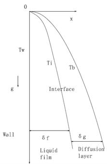
Figure 1. Diffusion boundary layer.
The condensation rate can be expressed by the mass transfer process, e.g. rate of diffusion of vapor towards the cold tube. Hence, the mass flux of the steam and non-condensable gas in the boundary layer can be expressed as follows:
(4)
(5)
where D represents the mass diffusion coefficient, w the mass fraction, v the mixture velocity, and n the normal direction to the wall (liquid film). The total mass flux at the liquid-vapor interface can be written as:
(6)
The vapor condensing mass flux at the wall is:
(7)
The vapor condensing mass flux can also be expressed as:
(8)
By introducing the number,
(9)
The mass flux of vapor condensing can be further expressed as:
(10)
The interface parameter is used in Equation (10) instead of wall parameter. By using the heat and mass transfer analogy (HMTA) and assuming the gas mixture flow is turbulent and naturally driven, one can express the Sherwood number according to a form analogous to the McAdams correlation for free convective flows:
(11)
The Sc number and Gr number can be expressed as follow,
(12)
(13)
As the sensible convection heat transfer is ignored, the condensation heat can be written as:
(14)
Then, we can obtain the total HTC as:
(15)
The enhancement in the mass transfer rate, which is due to the suction effect at the gas-liquid interface, can be determined by a free parameter f. And the parameter f depends solely on the Bird factor Θ. The f value will be estimated from the experimental data.
Finally, the total HTC can be expressed as:
(16)
The conduction through the liquid condensate (hf) is calculated by Kim’s model.
A physical model of the film condensation outside a vertical tube is described.
The thickness of the liquid film is:
(17)
where the is the thickness of film condensed on the cold plate.
Then, the local condensation HTC can be expressed as:
(18)
And the average condensation HTC of the tube is:
(19)
where the is the average condensation HTC on the vertical plate, which is deduced by Nusselt.
Then, the theoretical expressions are provided for the average heat transfer coefficient of vertical cylinder [7]. The heat transfer coefficient on a vertical tube is related to that on a flat plate. And a simple explicit expression is provided for the heat transfer coefficient on a vertical tube, which is depend on the radius of a vertical tube and the thickness of the condensate film.
Generally, the liquid film thickness is smaller than 1 mm. So, the tube radius is much larger than that of film thickness. According to the Equation (19), the effect of the tube radius on the variation of the condensation heat transfer coefficient can be ignored, as long as the radius of condenser tubes is much larger than the liquid film thickness.
3. Condensation Heat Transfer Calculation Procedure
In order to predict the heat transfer coefficient, the following parameters are needed: the containment pressure, containment temperature, the wall temperature. Different from the Dehbi’s model, the interface temperature should be calculated in the process.
1) Guess an interface temperature Ti.
2) Obtain the corresponding interface noncondensable mass fraction Wi using the Gibbs-Dalton ideal gas mixture relation and the assumption that steam is at saturation conditions.
3) Calculate the vapor condensation HTC at the interface (hcd) by (16).
4) Calculate the liquid condensate conduction resistance at the interface (hf) by (19).
5) Compute the heat flux across the condensate film by (3).
6) Judge the energy balance of the heat flux.
7) If the Ti iteration has not converged then go back to step 1.
8) Stop the calculation if the heat flux is balance between both sides of interface.
4. Results and Discussion
4.1. The Effect of Film Conduction
As less total HTC data are obtained by the present experiment, Dehbi’s data are used. The model described above was used for parametric studies to determine the impact of conduction through the liquid condensate.
The effect of film conductive thermal resistance is revealed in Figure 2. It is
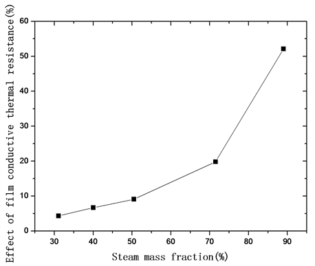
Figure 2. Effect of film conductive thermal resistance.
shown that the impact of conduction through the liquid condensate is small when the steam mass fraction is less than 70%. With the increasing of the steam mass fraction, the film conduction is more and more important. If it is not considered, the HTC deviation will be larger than 20%, which is not acceptable. So, the conduction through the liquid condensate (hf) is highly recommended to be included in the model especially when the Ws larger than 70%.
4.2. The Temperature Difference of Wall and Interface Temperature
The wall subcooling temperature is defined as the difference of wall and bulk temperature. And the interface subcooling temperature is defined as the difference of wall and interface temperature. As shown in Figure 3, the interface temperature decreases with the increasing of wall subcooling temperature. And the interface subcooling temperature increases with the increasing of wall subcooling temperature. When the wall subcooling temperature is 10˚C,the interface subcooling temperature is only 0.83˚C. When the wall subcooling temperature increase up to 53.5˚C,the interface subcooling temperature is 4.73˚C. The reason is that the increased wall subcooling temperature enhances the heat transfer rate. Then the thickness of the condensation film is increased, which results in the increase of interface subcooling temperature.
4.3. The Effect of Non-Condensable Gas Mass Fraction and Subcooling on HTC
The effect of non-condensable gas mass fraction and subcooling on HTC is shown in Figure 4. With the increasing of the wall subcooling, the thickness of
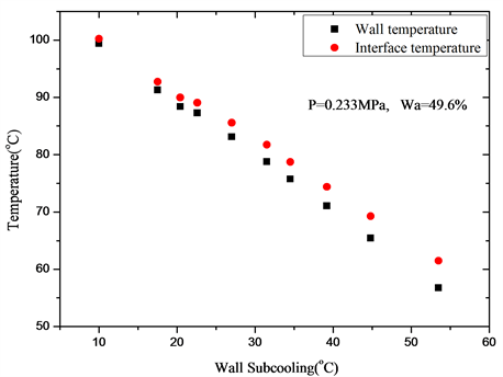
Figure 3. Effect of wall subcooling on interface temperature.
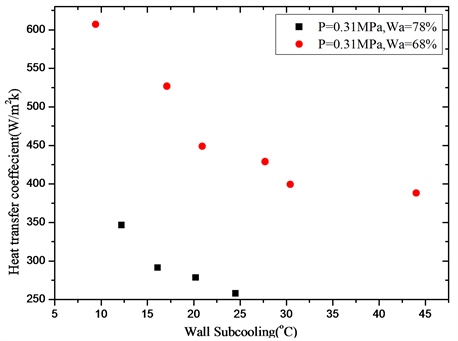
Figure 4. Effect of non-condensable gas mass fraction and subcooling on HTC.
the condensation film is increased, which increase the film conductivity resistance. Then the HTC decreases with the increase of wall subcooling. When the wall subcooling temperature increase from 12˚C to 24.5˚C,the HTC increases by 34%. And with the increasing of non-condensable gas mass fraction, the diffusion layer is accumulated near the tube. The mass transfer process is further inhibited, which results in the decrease of HTC. When the non-condensable gas mass fraction increase from 68% to 78% in 16˚C subcooling,the HTC decrease by 81%.
4.4. The Correlation of the Experiment Data
(20)
The unknown parameter in Equation (14), which is assumed to include the suction effect, is correlated with the data obtained by recent experiment. And the expression is provided in Equation (20). As is shown in Figure 5, more than 90% of the data are inside the band, and the standard deviation is about 19%.
5. Conclusions
A correlation based upon heat and mass transfer analogy method was improved by this investigation. The interface temperature is introduced and determined by iteration. The experiment is conducted and the data are used to fit for the enhanced factor. The influence of the steam mass fraction, total pressure and wall subcooling, on heat transfer coefficient are analyzed. The main conclusions are as follow:
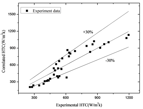
Figure 5. Effect of non-condensable gas mass fraction and subcooling on HTC.
1) The diffusion layer is modelled to simulate the heat transfer process of steam condensation with non-condensable gas on the vertical tube. Different with Dehibi’s model, the liquid film conduction resistance is introduced. And the interface temperature is solved by iterative. The heat balance across boundary layers between the liquid film and the vapor-gas mixture calculations can be reached by this process. Then the heat transfer correlation is improved.
2) The effect of different parameter on HTC is analyzed. With the increase of wall subcooling and mass fraction of non-condensable gas, the HTC decreases.
3) We now conduct the experiment study on the heat transfer in presence of non-condensable gas with a vertical tube of 2 m in length and 0.38m in diameter. In the experiment, the variation of condensation heat transfer coefficients with pressure, mass fraction of air, wall subcooling are investigated. The enhanced factor φ due to suction effect is correlated.
Acknowledgements
National Science and Technology Major Project of the Ministry of Science and Technology of China (No. 2015ZX06004004).
Cite this paper
Zhang, S.J., Cheng, X. and Shen, F. (2018) Condensation Heat Transfer with Non-Condensable Gas on a Vertical Tube. Energy and Power Engineering, 10, 25-34. https://doi.org/10.4236/epe.2018.104B004
References
- 1. Nusselt, W. (1916) De oberflachenkondensation des waserdampfes. Z. VDI, Frankfurt, 60, 541-546, 569-575.
- 2. Uchida, H., Oyama, A. and Togo, Y. (1965) Evaluation of Post-Incident Cooling Systems of Light-Water Power Reactors. Proceedings of International Conference on Peaceful Uses of Atomic Energy, 13, 93-102.
- 3. Dehbi, A.A. (1991) The Effects of Noncondensable Gases on Steamcondensation under Turbulent Natural Convection Conditions. Ph.D. Thesis, Department of Nuclear Engineering, MIT.
- 4. Liu, H., Todreas, N.E. and Driscoll, M.J. (2000) An Experimental Investigation of a Passive Cooling Unit for Nuclear Plant Containment. Nucl. Eng. Des., 199, 243-255. https://doi.org/10.1016/S0029-5493(00)00229-6
- 5. Su, J.Q., Sun, Z.N., Fan, G.M. and Ding, M. (2013) Experimental Study of the Effect of Non-Condensable Gases on Steam Condensation over a Vertical Tube External Surface. Nucl. Eng. Des., 5, 201-208. https://doi.org/10.1016/j.nucengdes.2013.05.002
- 6. Dehbi, A. (2015) A Generalized Correlation for Steam Condensation Rates in the Presence of Air under Turbulent Free Convection. Proceedings of ICAPP, France. https://doi.org/10.1016/j.ijheatmasstransfer.2015.02.034
- 7. Kim, S., Lee, Y.G. and Jerng, D.W. (2015) Laminar Film Condensation of Saturated Vapor on an Isothermal Vertical Cylinder. International Journal of Heat and Mass Transfer, 83, 545-551. https://doi.org/10.1016/j.ijheatmasstransfer.2014.12.009
- 8. Huhtiniemi, I.K. and Corradini, M.L. (1993) Condensation in the Presence of Noncondensable Gases. Nuclear Engineering and Design, 141, 429-446. https://doi.org/10.1016/0029-5493(93)90130-2
- 9. Herranz, L.E.., Anderson, M.H. and Corradini, M.L. (1998) A Diffusion Layer Model for Steam Condensation within the AP600 Containment. Nuclear Engineering and Design, 183, 133-150. https://doi.org/10.1016/S0029-5493(98)00164-2
- 10. Su, J.Q., Sun, Z.N. and Zhang, D.Y. (2014) Numerical Analysis of Steam Condensation over a Vertical Surface in Presence of Air. Annals of Nuclear Energy, 72, 268-276. https://doi.org/10.1016/j.anucene.2014.05.019
- 11. Colburn, A.P. (1934) Design of Cooler Condensers for Mixtures of Vapors with Noncondensing Uses. Industrial Engineering Chemical, 26, 1178-1182. https://doi.org/10.1021/ie50299a011