Open Access Library Journal
Vol.05 No.02(2018), Article ID:82345,14 pages
10.4236/oalib.1104267
Design of Drive System for Sensorless Brushless DC Motor Based on Model Reference Adaptive Control and Its Application in Horizontal Well Tractor
Zhou He, Yongjun Chen*, Bo Ruan, Shuhan Yu, Junwen Zhou
College of Electronics and Information, Yangtze University, Jingzhou, China

Copyright © 2018 by authors and Open Access Library Inc.
This work is licensed under the Creative Commons Attribution International License (CC BY 4.0).
http://creativecommons.org/licenses/by/4.0/


Received: December 18, 2017; Accepted: February 6, 2018; Published: February 9, 2018
ABSTRACT
The actual working environment temperature of the horizontal well tractor is too high, which leads to position sensor of general brushless DC motor (BLDCM) cannot work normally. Therefore, the position sensorless drive system is designed to overcome the problems caused by the position sensor in the actual working conditions. The principle of sensorless BLDCM work is introduced in detail, And drive system of Sensorless BLDCM was established by using simulation software. The use of three stage start make motor smoothly start, the motor speed detection based on model reference adaptive control (MRAC), ensures accurate commutation. Finally, the hardware and software design of the BLDCM system based on digital signal controller (DSC) is introduced and tested. The experimental results show that the drive system can start the BLDCM smoothly in the high temperature environment, and can quickly track the given speed, which meet the actual work demand of the horizontal well tractor.
Subject Areas:
Electric Engineering
Keywords:
Horizontal Well Tractor, Brushless DC Motor (BLDCM), Position Sensorless, Model Reference Adaptive Control (MRAC)

1. Introduction
As horizontal well technology is increasingly used in oil and gas development, horizontal well tractors have been proposed as a new type of downhole motion device. It can meet the delivery of logging tools and auxiliary work such as perforation and fishing to solve the problem that the instrument is difficult to be transported to a predetermined position in the downhole and horizontal wells by gravity.
Brushless DC Motor (BLDCM) is a new mechatronic product with many advantages such as stable structure, high power density, high efficiency, easy maintenance, long life and easy driving. It has been widely used in the fields of aerospace, automotive, robotics, household appliances and medical devices. Therefore, BLDCM has been chosen as drive motor of horizontal well tractor. The overall structure of the horizontal well tractor is shown in Figure 1.
However, due to the too high actual working environment temperature of the horizontal well tractor, the position sensor of general BLDCM cannot work normally [1] [2] [3] [4] . As a result, the general BLDCM will generate wrong commutation signals in this working environment, which may cause the motor lost step or even block turn. Therefore, the BLDCM used as drive motor of horizontal well tractor needs to adopt a positionless driving manner to overcome the problem caused by the position sensor in the actual working condition.
Based on the analysis principle of sensorless BLDCM work, the simulation of drive system for sensorless BLDCM was established by using PSIM simulation software [5] [6] . The use of three stage start make motor smoothly start, the motor speed detection based on model reference adaptive control (MRAC) [7] , ensures accurate commutation. Finally, the drive system for sensorless BLDCM was established based on digital signal controller (DSC) and tested. The experimental results show that the drive system can make BLDCM run stably in the high temperature environment and meet the actual working conditions of the horizontal well tractor.

Figure 1. The overall structure of the horizontal well tractor.
2. The Principle of Sensorless BLDCM Work
2.1. The Mathematical Model of BLDCM
BLDCM selected by horizontal well tractor is star connection and the central node is not led out, its equivalent circuit shown in Figure 2.
According to Kirchhoff’s voltage law, the equation of phase voltage can be obtained as follows:
(1)
in type: ―Voltage of each phase to the ground;
―Phase current;
―Back EMF, are back EMF coefficient and rotor mechanical speed;
―Phase resistance;
―Equivalent inductance of stator winding, are self inductance of stator winding and mutual inductance between stator winding;
―Central node voltage of motor armature winding.
2.2. Principle of Back EMF Zero Crossing Detection
The back EMF of BLDCM is a trapezoidal wave, the current is a square wave, and the phase current of each phase winding must be consistent with the back EMF in order for the BLDCM to output the maximum torque. Therefore, Commutation is required for every 60°electric angle in one electric period. Relation of back EMF and current in BLDCM as shown in Figure 3. It can be seen from Figure 3 that back EMF zero crossing point leading the current commutation signal 30˚ in each phase winding, So, The commutation time can be got according to the back-EMF zero crossing point. The motor back EMF can not be measured directly, so, It is necessary to calculate the equivalent voltage by phase voltage.
Set x phase is the non-conducting phase, the phase current is 0, according to Equation (1) can be got:
(2)
It can be seen from Equation (2) that the commutation signal can be obtained
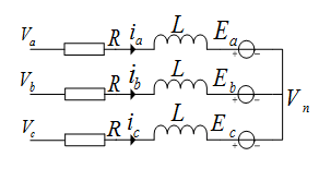
Figure 2. Equivalent circuit of a star connection BLDCM.

Figure 3. Relation diagram of back EMF and current.
indirectly by comparing the relationship between the phase voltage and the central node voltage.
Since the center node of the motor selected by the drive system is not led out, it is necessary to fabricate the motor central node voltage.
As a BLDCM, there are only two phases which have current at the same time, Due to conducting two-phase current equal to the opposite direction, the other a phase current is 0, from Equation (1) can be got:
(3)
It can be seen from Figure 2 that the sum of the three phase back EMF is zero when the back-EMF zero crossing, so, the central node voltage at this time can be got as:
(4)
3. Simulation and Analysis of Sensorless BLDCM Drive System Based on PSIM
According to the above analysis, Block diagram of drive system for sensorless BLDCM shown in Figure 4, the drive system uses speed, current double closed- loop control.
PSIM is a computer simulation software specially designed for power electronics and motor control. It provides a powerful simulation environment for the research of power electronics analysis and digital control motor drive, and uses
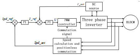
Figure 4.Sensorless BLDCM drive system block diagram.
PSIM to establish drive system of sensorless BLDCM according to Figure 3. The parameters of the motor are as follows: The stator resistance is 11.9 Ω, the stator inductance is 2.07 mH, the stator mutual inductance is 0.69 mH, the number of motor pole pairs is 2, the back EMF coefficient is 16.15 V・krpm−1, the moment of inertia is 0.007 g・m2, the friction coefficient is 1.167 g・m2・s−1, the inverter input voltage is 300 V, the given speed is 6000 rpm.
3.1. Three Stage Start of Sensorless BLDCM
Since the back EMF increases with the increase of speed, the back EMF zero- crossing detection is not suitable for motor starting. The drive system adopts three stage start algorithm when the motor is starting, namely, the rotor pre-positioning, external synchronous acceleration, self-synchronization. Figure 5 and Figure 6 are diagrams of rotor position using a three stage start algorithm.
From Figure 5 and Figure 6 shows, the use of three stage start algorithm can be achieved smooth start of the motor. Figure 7 is the motor speed response curve.
It can be seen from Figure 7, the use of three stage start algorithm to start, the speed can be in a relatively short period of time to track the given speed to achieve the desired start effect. Figure 8 is the a phase voltage, PWM and current after switch to self-synchronizing.
Visible, the simulation results consistent with the previous theoretical analysis, the back-EMF zero-crossing lead the phase commutation signal 30˚ electrical angle.
3.2. BLDCM Speed Detection Based on Model Reference Adaptive Control
Based on the above analysis, Commutation of sensorless BLDCM based on the back-EMF zero-crossing detection needs to delay 30˚ electric angle time according to speed, therefore, the accuracy of speed detection is crucial for commutation of sensorless BLDCM. The traditional speed detection is calculated by the time difference between two commutation signals. The obtained speed is the average speed between two commutation signals, which is not accurate enough, so commutation can not be performed at the optimum commutation time, So it is

Figure 5. Diagrams of rotor position with an initial electric angle of 0 degrees.

Figure 6. Diagrams of rotor position with an initial electric angle of 200 degrees.

Figure 7. Motor speed response curve.

Figure 8. The a phase voltage, PWM and current after switch to self-synchronizing.
necessary to find a more accurate method of speed detection.
For BLDCM, when the current from phase a to phase b is considered. There are following equations:
(5)
According to the formula (1) the line voltage between phase a and phase b can be obtained:
(6)
In stable condition, . Then, (6) can be rewritten as:
(7)
According to Equation (7), the motor speed can be calculated according to the line voltage and phase current, but the motor windings resistance could change with the change of temperature. Therefore, BLDCM speed detection based on model reference adaptive control (MRAC) is proposed. As shown in Figure 9.
As can be seen from Figure 9, the main module of speed detection is a model reference adaptive regulator, is speed estimated by line voltage and phase current, is speed calculated by the commutation signal, The input of regulator is the deviation of the two speed, the output of the regulator is a correction variable quantity to estimate the speed.
When the motor stator winding resistance increases from 11.9 Ω to 15.9 Ω, the actual motor speed, the speed calculated based on the fixed resistor value, the
Figure 9. BLDCM speed detection based on model reference adaptive.

Figure 10. Comparison of several speed detection methods.
speed detected based on the commutation signal and the estimated speed based on the MRAC are shown in Figure 10.
It can be seen from Figure 10 that after the change of the resistance of the stator winding of the motor, the estimated speed based on the MRAC is the closest to the actual speed.
4. Actual Test and Result Analysis of Drive System for Sensorless BLDCM
4.1. DSC Based Drive System of Sensorless BLDCM
Drive system of sensorless BLDCM includes two parts: software and hardware, the software part includes the main program and several subroutines and interrupt service functions, the main function is to achieve BLDCM without position start, commutation, PWM duty cycle setting and communicate with the upper computer. The hardware part includes the controller, drive circuit, three phase inverter, voltage and current sampling circuit. and the overall structure of the drive system is shown in Figure 11.
As the actual working environment temperature of the horizontal well tractor is too high, there are high requirements on the controller. Therefore, the controller of the drive system adopts the dsPIC series chip of the MICROCHIP company.
Figure 11. The overall structure of the drive system for sensorless BLDCM.
The control chip is a kind of motor-specific control chip with digital signal processor (DSP) computing function. It can withstand underground high temperature environment and meet the actual working conditions of horizontal well tractors. As the IGBTs that form the three phase inverter need certain voltage and power to trigger, Therefore, a driving circuit composed of the driver chip IR2233 and its corresponding peripheral circuits is added between the controller and the three phase inverter. The specific design of the driving circuit and the inverter circuit is shown in Figure 12.
As the drive system uses PWM technology, which results in a large number of chopping components in the detected voltage and current, which will interfere with the sampling, therefore, It is necessary to add a filter capacitor in the sampling circuit.
As can be seen from Figure 11, the drive system uses double closed-loop speed and current control, the controller receives commands through the communication with the upper computer to obtain the desired speed of the motor, after the motor is started and switched to self-synchronous by the three stage start algorithm, Estimate the actual motor speed based on MRAC, DC bus current obtained through the current sampling circuit, and then through the speed regulator and current regulator to obtain the corresponding PWM duty cycle, so that the motor speed reaches the desired speed.
After switch to self-synchronizing, through the ADC interrupt service function to complete the acquisition of phase voltage, and then according to equation (4) fictitious motor central node voltage and compared with each phase voltage, and then by the PWM interrupt service function using majority functions to detect the back-EMF zero point, if true then calculate the 30˚ electrical angle of time according to speed and start the timer for commutation of sensorless BLDCM. As the sampling circuit introduces a filter capacitor nonlinear element, Resulting in a phase shift between the detected zero crossing point of the back EMF and the actual zero crossing point. Therefore, the delay phase needs to be compensated according to speed.
Figure 12. Design of specific driving circuit and inverter circuit.
4.2. Experimental Results and Analysis
The structure of the body, rotor and stator of the motor used in the drive system are shown in Figure 13 and Figure 14.
In order to facilitate the test of the drive system, we designed a monitoring and control software for upper computer based on the serial port, which can monitor the motor speed and PWM duty cycle. Figure 15 shows the Phase voltage waveform diagram before and after filtering. Figure 16 the modulation signal of the upper bridge and phase voltage waveform. Figure 17 and Figure 18 are motor speed and PWM duty cycle obtained by the software at a temperature of 150˚C. Figure 19 is the modulation signal of the upper bridge and phase voltage waveform when the motor speed is 6000 rpm.

Figure 13. Structure diagram of motor body.

Figure 14. Structure diagram of rotor and stator.

Figure 15. Phase voltage waveform diagram before and after filtering.

Figure 16. The modulation signal of the upper bridge and the phase voltage waveform diagram.

Figure 17. Motor speed.

Figure 18. Pwm duty cycle.

Figure 19. The modulation signal and phase voltage waveform of the upper bridge when the speed is 6000 rpm.
From the experimental results, it can be seen that the drive system for sensorless BLDCM based on DSC can realize the smooth start of BLDCM in high temperature environment and can track the given speed rapidly.
5. Conclusion
In this paper, based on the analysis of BLDCM for horizontal well tractor, a drive system of sensorless BLDCM for horizontal well tractor is designed, which uses three stage start algorithms and speed detections based on model adaptive control. The simulation and experimental results show that the drive system can make the BLDCM start and run smoothly in the high temperature environment and can track the given speed quickly to meet the actual working requirements of the horizontal well tractor.
Cite this paper
He, Z., Chen, Y.J., Ruan, B., Yu, S.H. and Zhou, J.W. (2018) Design of Drive System for Sensorless Brushless DC Motor Based on Model Re- ference Adaptive Control and Its Appli- cation in Horizontal Well Tractor. Open Access Library Journal, 5: e4267. https://doi.org/10.4236/oalib.1104267
References
- 1. Yu, S.H. and Chen, Y.J. (2017) A New Strategy for BLDC Sensorless Control System and Its Application in Horizontal Well Tractor. Open Access Library Journal, 4, e3844.
https://doi.org/10.4236/oalib.1103844 - 2. Chen, S.H., Liu, G., Zheng, S.Q., et al. (2017) Sensorless Control of BLDCM Drive for a High-Speed Maglev Blower Using Low-Pass Filter. IEEE Transactions on Power Electronics, 32, 8845-8856.
https://doi.org/10.1109/TPEL.2016.2645782 - 3. Lai, Y.-S. and Lin, Y.-K. (2011) A Unified Approach to Zero-Crossing Point Detection of Back EMF for Brushless DC Motor Drives without Current and Hall Sensors. IEEE Transactions on Power Electronics, 26, 1704-1713.
- 4. Wang, H.-P. and Liu, Y.-T. (2006) Integrated Design of Speed-Sensorless and Adaptive Speed Controller for a Brushless DC Motor. IEEE Transactions on Power Electronics, 21, 518-523.
https://doi.org/10.1109/TPEL.2005.869772 - 5. Xia, C.L. and Li, X.M. (2015) Z-Source Inverter-Based Approach to the Zero-Crossing Point Detection of Back EMF for Sensorless Brushless DC Motor. IEEE Transactions on Power Electronics, 30, 1488-1498.
- 6. Wang, H.-B. and Liu, H.-P. (2009) A Novel Sensorless Control Method for Brushless DC Motor. IET Electric Power Applications, 3, 240-246.
- 7. Liu, Y., Zhao, J., Xia, M., et al. (2014) Model Reference Adaptive Control-Based Speed Control of Brushless DC Motors with Low-Resolution Hall-Effect Sensors. IEEE Transactions on Power Electronics, 29, 1514-1522.