Int. J. Communications, Network and System Sciences, 2011, 4, 667-673
doi:10.4236/ijcns.2011.410082 Published Online October 2011 (http://www.SciRP.org/journal/ijcns)
Copyright © 2011 SciRes. IJCNS
Route Optimization for Network Mobility Based
Aeronautical Network Using Correspondent Router
Ruoshan Kong, Jing Feng, Huaibei Zhou
International School of Software, Wuhan University, Wuhan, China
E-mail: krs1024@public.wh.hb.cn
Received May 21, 2011; revised August 10, 2011; accepted September 26, 2011
Abstract
The future aeronautical network will be based on IPv6 and the services over the aeronautical network will be
classified into 3 domains: Air Traffic Services (ATS), Airline Operational Services (AOS) and Passenger
Information and Entertainment Services (PIES), among which the ATS and AOS domains are important for
aircraft safety and airline business operation. Some schemes have been proposed to provide IP mobility sup-
port for aeronautical network, and Network Mobility (NEMO) scheme is the most promising one. However,
using NEMO technology will lead to sub-optimal routing, so route optimization technology is highly desired
for NEMO. A route optimization scheme is proposed for the ATS and AOS domains, which introduces the
Correspondent Routers to realize the optimal routing and employs an improved procedure to reduce the
handoff delay. The route optimization for the PIES domain is also discussed to provide better performance
for some special scenarios.
Keywords: Aeronautical Network, Network Mobility, Route Optimization, Correspondent Router
1. Introduction
While the Internet has been widely used in more and more
areas, civil aviation industry is still using traditional ana-
logue technologies for communications, which will become
a bottleneck for the future development of the industry.
IPv6 will be an inevitable choice for the next generation of
aeronautical network and has been discussed by the Interna-
tional Civil Aviation Organi- zation (ICAO) [1].
An important feature of the Aeronautical network is
that the data flows to/from the aircraft are classified into
3 domains [2] (see Figure 1):
Air Traffic Services Domain (ATS): this domain in-
cludes the data flows that are critical to the safety of
the flight between the aircraft and the ground stations.
The ground stations are deployed in different locations
and an aircraft always connects to and communicates
with the ground station that is geographically and
topologically close to itself. Some ground stations
have their own access networks and some stations
make use of the access networks provided by ISPs, so
generally speaking the ground stations are topologi-
cally close to their access networks.
Airline Operational Services Domain (AOS): this do-
main includes some data flows between an aircraft and
the operational center of the airline corporation. These
data flows are not critical to the safety but important
for business and airline operations. Different from the
ATS domain, the communication peer in the AOS do-
main may be geographically remote from the aircraft.
Passenger Information and Entertainment Services
domain (PIES): this domain is to provide Internet ac-
cess to the passengers, so it is relatively less impor-
tant, and the communication peers in this domain are
globally located.
For safety and bandwidth consideration, an aircraft
employs multiple link technologies for data communica-
tions, such as P34, LDL, WCDMA, WiMAX, and satel-
lite, and the data flows of the 3 domains should be sepa-
rately handled by different routing systems in an aircraft.
Several schemes have been proposed for the aeronaut-
tical network to support IP communications, including
the Border Gateway Protocol based, the Network Mo-
bility (NEMO) based, and the Host Identity Protocol
based. Among these schemes, the NEMO based scheme
has advantages in many aspects such as mobility sup-
port, scalability and security, but the end-to-end packet
delay is an important drawback of NEMO due to the
R. S. KONG ET AL.
668
Figure 1. Topology of the aeronautical network.
sub-optimal routing [3]. This paper proposes a route op-
timization scheme for the NEMO based aeronautical
network, which aims to set up optimal routing and re-
duce the handoff delay.
The rest of the paper is organized as follows: in Sec-
tion 2 some related works are introduced, in Section 3 an
optimization scheme for the ATS and AOS domains is
introduced, in Section 4 some possible optimization
methods for the PIES domain are discussed, and finally
in Section 5 is the conclusion.
2. Related Works
2.1. Network Mobility
Network Mobility (NEMO) was proposed based on Mo-
bile IPv6 [4] to support mobility for a Local Area Net-
work (LAN). A Mobile Network consists of a Mobile
Router (MR) and some Mobile Network Nodes that take
the MR as the default router, through which the mobile
network attaches to the Internet.
The home registration procedure is defined in the
NEMO basic support protocol [5]: the MR gets a Care-of
Address from the foreign network, and then sends a
Binding Update (BU) message to its Home Agent (HA)
to bind the Mobile Network’s Prefix to the Care-of Ad-
dress, then an IP-in-IP tunnel is set up between the MR
and the HA, and all the traffic to/from the mobile net-
work will be encapsulated into the tunnel and forwarded
by the HA, which leads to the “triangular routing”.
If the MR is equipped with multiple egress wireless
interfaces, it can get multiple Care-of Addresses from
different Access Networks. Following [6], the MR can
make use of all these Care-of Addresses simultaneously
and thus improve the availability and the bandwidth.
NEMO fits the aeronautical network quite well. The
aircraft can be regarded as a Mobile Network consisting
of a router and multiple LAN nodes. These LAN nodes
can be sensor nodes in the ATS or AOS domain, or mo-
bile devices taken by passengers in the PIES domain.
The ground stations in the ATS domain, the operational
center of the AOS domain and all the Internet hosts in
the PIES domain can be regarded as the Correspondent
Nodes (CN).
2.2. Typical Schemes to Provide IP Mobility
Support
[3] makes an overview on the typical schemes for aero-
nautical networks to support IPv6 mobility, including the
Border Gateway protocol, the IPSec gateway scheme, the
NEMO scheme, the SCTP protocol and the HIP protocol.
This paper analyzes all these schemes on the following
aspects:
Session Continuity
Mobile Network Support
Multihoming
Security
End-to-end delay
Scalability
Applicability to PIES domain
Convergence time
ATS Flow
ATS CN
ATS CN
AOS CN
Common
Internet Node
Common
Internet Node
AOS Flow
PIES Flow
C
opyright © 2011 SciRes. IJCNS
R. S. KONG ET AL.669
Efficiency
Ground-initiated communications.
The authors conclude that the NEMO scheme has the
best feasibility and overall performance, while the main
drawback of this scheme is the end-to-end packet delay
brought by the sub-optimal routing, so a route optimiza-
tion scheme is desired.
2.3. Route Optimization for NEMO Based
Aeronautical Network
Some route optimization schemes have been proposed,
and the ORC scheme [7] is a typical one. This scheme
introduces the Correspondent Router (CR) which covers
a certain number of Correspondent Nodes (CN), and the
MR can set up an IP-in-IP tunnel with the CR and bind
the Mobile Network’s prefix to the MR’s Care-of Ad-
dress so that the packets to/from the CN will be encap-
sulated into the MR-CR tunnel and forwarded by the CR
without bypassing the HA (see Figure 2).
[8] employs the prefix delegation technology to ex-
pose the prefix of the access network to the Mobile Net-
work Nodes, so that each Mobile Network Node can
launch route optimization in the traditional Mobile IPv6
manner.
[9] proposes an optimization scheme similar to that in
[8], but requests that the MR launch route optimization
for each of the Mobile Network Nodes.
However, all these optimization schemes are proposed
for general scenario and none of them are specially de-
signed for the aeronautical networks, so [2] lists the re-
quired characteristics and desirable characteristics of
route optimization for NEMO aeronautical networks.
[3] analyzes the above mentioned route optimization
schemes and makes comparison on their applicability to
aeronautical network. It concludes that [8] and [9] have
signaling overhead problems because the route optimiza-
tion has to be performed separately for each Mobile Net-
work Node, while the ORC scheme has relatively good
performance and some limitations in signaling security.
[3] also mentions another route optimization scheme
for NEMO aeronautical networksmulti-HA scheme.
Multiple HAs locate in different regions and the aircraft
Figure 2. Routing of the ORC scheme.
(Mobile Network) switches between the HAs according
to the geographical and topological position. This
scheme cannot prevent the “triangular routing”, but the
aircraft can choose the nearest HA to prevent further
deterioration on packet delay. This scheme looks nice but
the feasibility is questionable because it’s impossible for
multiple HAs in different regions to cover the same
Home Address, and the handoff between HAs will lead
to the change of Home Address.
Some other route optimization schemes for NEMO
aeronautical networks can also be found. [10] proposes
to combine the NEMO and Ad hoc technologies, but this
scheme only aims at the PIES domain and is suitable
only for some special areas such as the North Atlantic.
3. Route Optimization for ATS and AOS
Domains
Compared with the PIES domain, the ATS and AOS do-
mains are different in the following aspects:
ATS and AOS domains are much more important for
safety and airline business and so require high avail-
ability, while the PIES domain is less important;
ATS and AOS domains require relatively low band-
width, while the PIES domain is bandwidth consum-
ing;
The CNs in the ATS and AOS domains are limited in
number and are specially deployed by specific organi-
zations, while the CNs in the PIES domain are com-
mon Internet nodes.
Considering the above differences, our scheme treats
the PIES domain separately, and the optimization policies
used by the PIES domain are different from what is em-
ployed in the ATS and AOS domains.
3.1. Basic Mechanism for Route Optimization
Our scheme requires each CN in the ATS or AOS do-
mains is equipped with a Correspondent Router (CR),
and the basic mechanism for route optimization is the
same as that of the ORC scheme [7]. This requirement
for infrastructure is reasonable and feasible because the
CNs in the ATS and AOS domains are limited in
number and deployed for special use.
The CR is the gateway router of the leaf network
where the CN locates, so the CR can capture all the
packets to/from the CN.
An MR can send a Binding Update (BU) message to
the CR which includes the Mobile Network Prefix and
the Care-of Address. The CR replies with a Binding
Acknowledgement (BA) message on receiving the BU,
from which the MR can get the prefix of the leaf net-
work managed by the CR. Hence the IP-in-IP tunnel
Internet CR CN1
HA CN2
LFN
MR
Normal Path Optimized Path
Copyright © 2011 SciRes. IJCNS
R. S. KONG ET AL.
670
between the MR and the CR is set up, and the MR will
encapsulate all the packets from the Mobile Network
Node to the CN with an outer IP header (source: MR’s
Care-of Address; destination: CR), while the CR will
encapsulate all the packets from the CN to the Mobile
Network Node with an outer IP header (source: CR;
destination: MR’s Care-of Address).
These encapsulated packets are sent to/from the
MR’s Care-of Address, so can be directly transferred
without bypassing the HA, and the optimal routing is
realized.
3.2. CR Discovery and Return Routability
Procedure
A CR can be deployed by different organizations such as
the government, the airline company, or the ISP, so it’s
quite probable that the aircraft doesn’t know the CR’s
information and there must be some mechanism for the
MR to find out the CR in front of the CN. The ORC
scheme [7] solves this issue by using the IPv6 anycast
technology [11].
An anycast addressa predefined IPv6 suffixis
allocated to each CR besides its own unicast address.
The MR can send an ICMP CR Discovery Request
message to this anycast address (the CN’s prefix + the
predefined suffix), and the message will be captured and
replied by the CR, then the MR will get the CR infor-
mation and launch route optimization to the CR.
As we have mentioned in section 2.3, the signaling
security is not fully discussed in [7]. In Mobile IPv6 [4],
a mobile node must finish the “Return Routability
Procedure” to prove it is the true owner of the Home
Address and the Care-of Address before it can set up
route optimization with a CN. As Figure 3 shows, the
mobile node sends a Home Test Init (HoTI) message
with its Home Address and a Care-of Test Init (CoTI)
message with its Care-of Address to the CN, and the CN
replies with Home Test (HoT) message and Care-of Test
(CoT) message respectively. Both HoT and CoT contain
a part of the authentication information, and the mobile
node has to receive both messages to obtain the full
authentication information needed in BU message.
The basic idea of the “Return Routability Procedure”
can be used between the MR and the CR, but the details
must be updated because it is insufficient for the MR to
prove it owns both the Home Address and the Care-of
Address. The MR must prove that it is the true router of
the Mobile Network Prefix through this procedure.
[12] proposes an extension to the procedure, but [13]
finds a potential risk in this extension and further
improves it as follows (see Figure 4 ):
The MR sends the HoTI message to the CR, which
Figure 3. Return Routability Procedure signaling.
Figure 4. Signaling of improved Return Routability Pro-
cedure.
contains the Mobile Network Prefix and uses the
MR’s Home Address as the source address.
The CR replies with two Network Prefix Test (NPT)
messages on receiving the HoTI message, both of
which contains a part of the authentication infor-
mation. The two NPT messages are not sent to the
MR’s Home Address. The destination address of an
NPT message is randomly generated based on the
Mobile Network Prefix obtained from the HoTI
message (i.e. Mobile Network Prefix + randomly
generated suffix), and the highest bit of the randomly
generated suffix of the 2 NPT messages must be 0
and 1 respectively.
The MR sends the CoTI message to the CR, which
uses the MR’s Care-of Address as the source address.
The CR replies with a CoT message which contains
another part of the authentication information to the
MR’s Care-of Address.
The MR must receive the CoT message and capture
the 2 NPT messages so as to collect all the authen-
tication information, then it can send the BU message
with full authentication information to the CR to set up
optimal routing.
The security of the above procedure is proved in [13],
and the signaling security limitation of the CR mecha-
nism can be resolved with this improved “Return Rou-
Mobile NodeHA CN
Home Test Init message
Home Test message
Care-of Test Init message
Care-of Test message
MR HA CR
Home Test Init message
Network Prefix Test message (1)
Network Prefix Test message (2)
Care-of Test Init message
Care-of Test message
Copyright © 2011 SciRes. IJCNS
R. S. KONG ET AL.671
8
8
tability Procedure”.
3.3. Handoff Acceleration
When an aircraft switches from one Access Router to
another, it has to perform the following steps:
Step 1: Automatically configure the new Care-of Ad-
dress from the new Access Router.
Step 2: Wait for a period of time for the “Duplicate
Address Detection (DAD)” [14].
Step 3: Home registration.
Step 4: Perform Return Routability Procedure with the
CR.
Step 5: Send BU message to the CR to restore the
traffic to the CN.
Step 6: If the aircraft needs to switch to a new ground
station (CN), it should discover the new CR in front
of the new CN.
Step 7: Perform Return Routability Procedure with the
new CR.
Step 8: Send BU message to the new CR to set up
optimal routing with the new CN (ground station).
So the total handoff delay can be expressed as:
12 7
12 5
(switch to new CN)
(the same CN)
s
tep stepstepstep
s
tep stepstepstep
TT TT
TTT TT


(1)
The delay may lead to interrupt of communications
with the ground station, which can bring potential risk,
and also the aircraft has to suffer from sub-optimal rout-
ing to the new ground station from Step 3 to Step 8,
which can affect the quality of communications.
In order to accelerate the handoff procedure, we raise
some new requirements to the Access Network. Consid-
ering the Access Networks are specially deployed for
future IPv6 based aeronautical network, we believe these
requirements are acceptable.
Every Access Router can inform the aircraft about the
geographical scope it covers, by means of, for exam-
ple, providing the coordinates of all the base stations
and antennas, so that the aircraft can predict its hand-
off tendency with the help of GPS.
Every Access Router maintains the basic information
of all the neighboring Access Routers, including their
IP addresses, geographical coverage and the prefixes
managed by them.
Every Access Router maintains a “Neighbor Aircraft
List” which includes the IP addresses of the aircrafts
that are currently served by a neighboring Access
Router but may switch to this Access Router soon.
Once an IP address is inserted into this list, it means
the IP has been “booked” and the Access Router will
protect the IP in the future “Duplicate Address Detec-
tion (DAD)” process.
The MR obtains from its Access Router and main-
tains the basic information of current and all the
neighboring Access Routers, including their IP ad-
dresses, geographical coverage and the prefixes man-
aged by them. The handoff process is modified as
Figure 5 shows.
When an aircraft compares its coordinates with current
Access Router (ARa)’s geographical coverage and finds
that it will switch to another Access Router (ARb) soon,
the MR calculates the automatically configured address
(IPb) under ARb in advance and sends a “Neighbor DAD
Request” message to ARa which contains IPb and ARb’s IP
address. ARa forwards this message to ARb. Then ARb
performs the “Duplicate Address Detection (DAD)” for
IPb. If no duplicate address is found, ARb will reply with a
“Neighbor DAD Complete” message to the MR and in-
serts IPb into the “Neighbor Aircraft List”; if a duplicate
address is found, ARb will generate another available ad-
dress (IPc) and send it to MR with a “Neighbor DAD Fail”
message, also IPc will be inserted into the “Neighbor Air-
craft List”. In this way, the DAD process can be finished
Calculate the IP address under new
Access Route
r
New Access Router performs DAD
procedure
CR discovery (if the aircraft will
switch to a new CN
)
Return Routability Procedure phase 1
Send HoTI and capture 2 NPT
Figure 5. Optimized handoff process.
Return Routability Procedure phase 2
Send CoTI and receive CoT
Configure new Care-of Address
Home
Registration
before
handoff
after
handoff
Send BU to CR
Copyright © 2011 SciRes. IJCNS
R. S. KONG ET AL.
672
ously.
8
4.2. CR based Scheme
before the handoff and the delay caused by DAD can be
avoided.
If the aircraft finds that it will switch to a new CN
(ground station), the MR can perform the CR discovery
before handoff.
The MR has to perform Return Routability Procedure
and update the binding for each CR after handoff, but the
process can be optimized to shorten the delay. The MR
can send out the HoTI message (with MR’s Home
Address as source address) and capture the 2 NPT
messages before handoff, then when the MR switches to
the new Access Router and finish configuring the new
Care-of Address, it can send out the CoT message (to the
CR, with the Care-of Address as the source address) and
the BU message (to the HA for Home Registration)
simultane
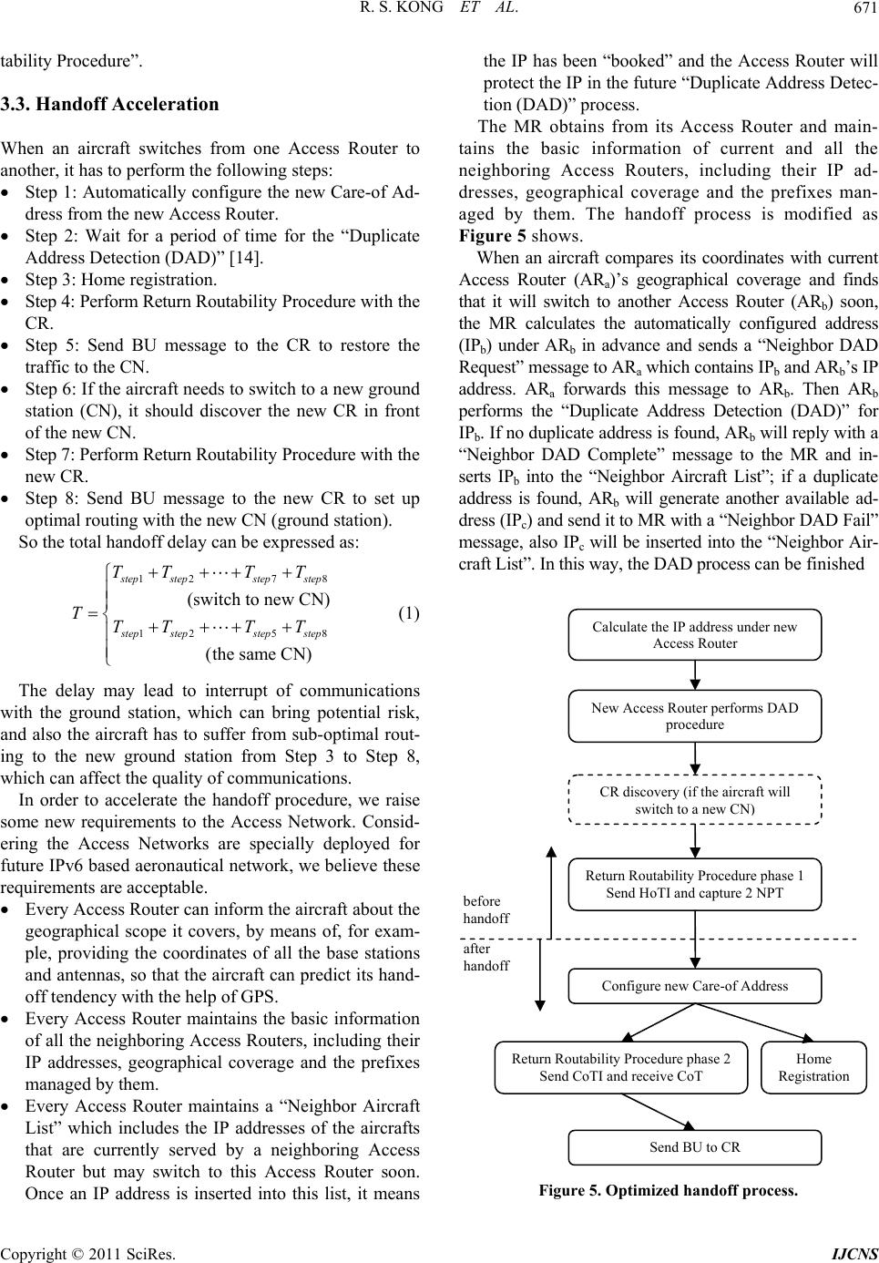
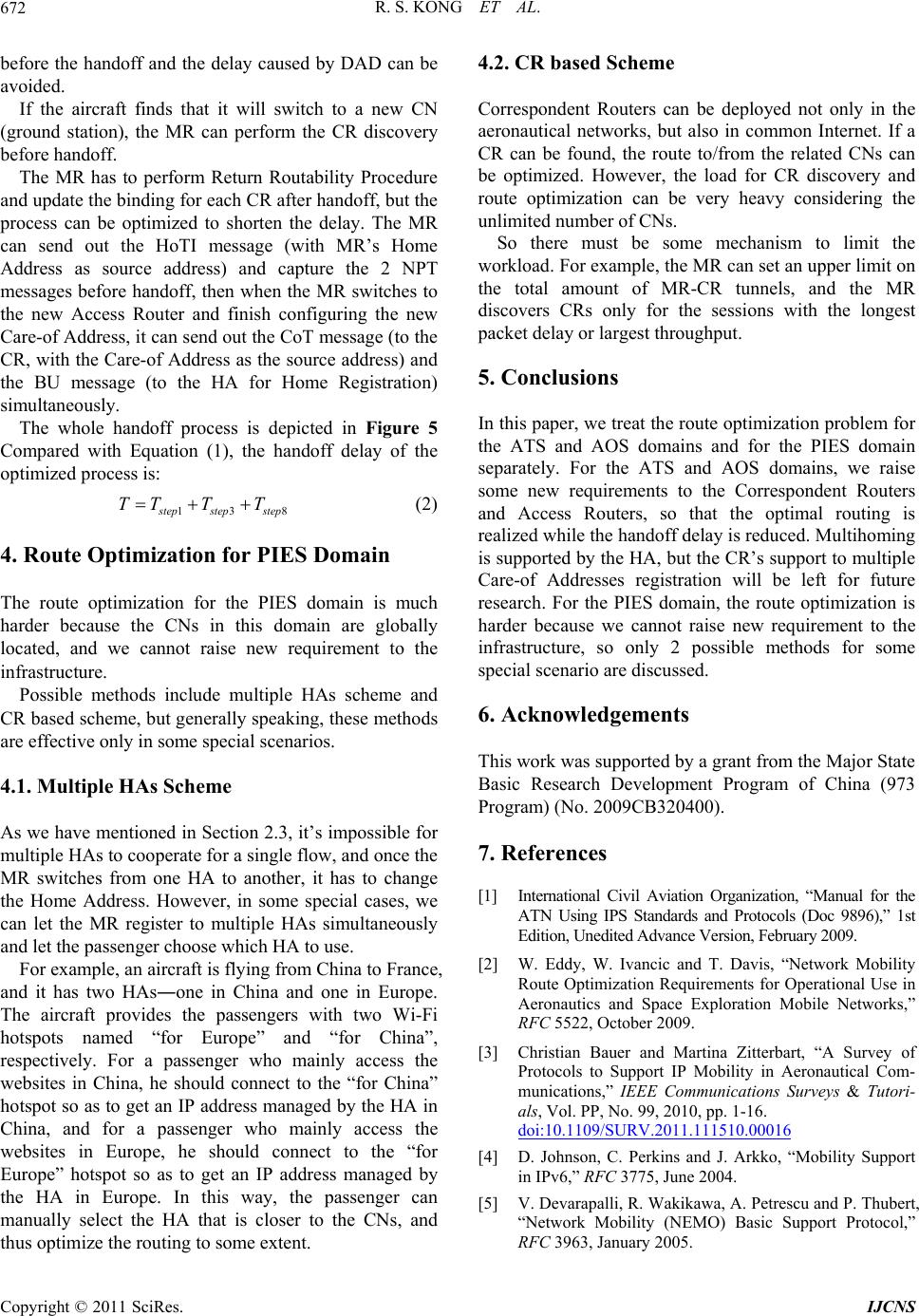
The whole handoff process is depicted in Figure 5
Compared with Equation (1), the handoff delay of the
optimized process is:
13
s
tep stepstep
TT TT (2)
4. Route Optimization for PIES Domain
The route optimization for the PIES domain is much
harder because the CNs in this domain are globally
located, and we cannot raise new requirement to the
infrastructure.
the routing to some extent.
throughput.
d.
Possible methods include multiple HAs scheme and
CR based scheme, but generally speaking, these methods
are effective only in some special scenarios.
4.1. Multiple HAs Scheme
As we have mentioned in Section 2.3, it’s impossible for
multiple HAs to cooperate for a single flow, and once the
MR switches from one HA to another, it has to change
the Home Address. However, in some special cases, we
can let the MR register to multiple HAs simultaneously
and let the passenger choose which HA to use.
For example, an aircraft is flying from China to France,
and it has two HAsone in China and one in Europe.
The aircraft provides the passengers with two Wi-Fi
hotspots named “for Europe” and “for China”,
respectively. For a passenger who mainly access the
websites in China, he should connect to the “for China”
hotspot so as to get an IP address managed by the HA in
China, and for a passenger who mainly access the
websites in Europe, he should connect to the “for
Europe” hotspot so as to get an IP address managed by
the HA in Europe. In this way, the passenger can
manually select the HA that is closer to the CNs, and
thus optimize
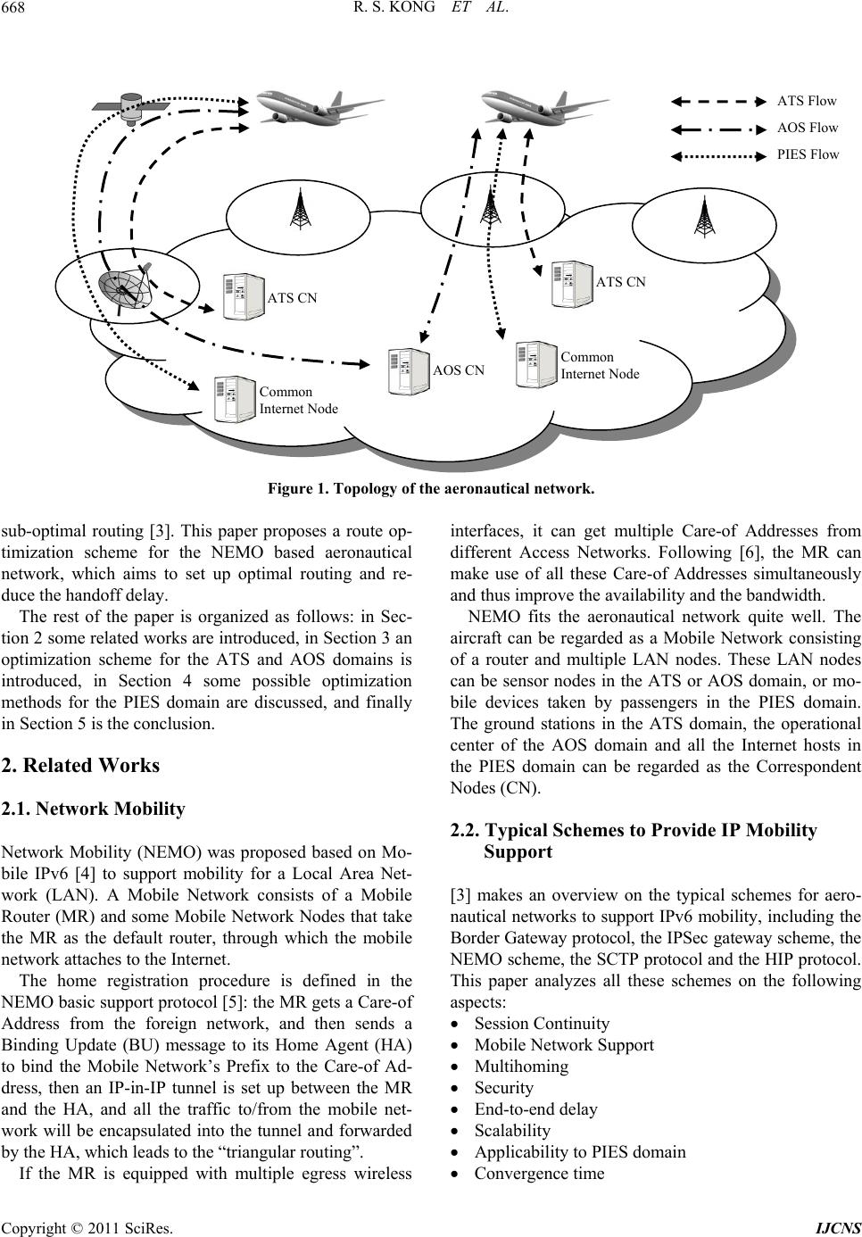
Correspondent Routers can be deployed not only in the
aeronautical networks, but also in common Internet. If a
CR can be found, the route to/from the related CNs can
be optimized. However, the load for CR discovery and
route optimization can be very heavy considering the
unlimited number of CNs.
So there must be some mechanism to limit the
workload. For example, the MR can set an upper limit on
the total amount of MR-CR tunnels, and the MR
discovers CRs only for the sessions with the longest
packet delay or largest
5. Conclusions
In this paper, we treat the route optimization problem for
the ATS and AOS domains and for the PIES domain
separately. For the ATS and AOS domains, we raise
some new requirements to the Correspondent Routers
and Access Routers, so that the optimal routing is
realized while the handoff delay is reduced. Multihoming
is supported by the HA, but the CR’s support to multiple
Care-of Addresses registration will be left for future
research. For the PIES domain, the route optimization is
harder because we cannot raise new requirement to the
infrastructure, so only 2 possible methods for some
special scenario are discusse
6. Acknowledgements
This work was supported by a grant from the Major State
Basic Research Development Program of China (973
Program) (No. 2009CB320400).
7. References
[1] International Civil Aviation Organization, “Manual for the
ATN Using IPS Standards and Protocols (Doc 9896),” 1st
Edition, Unedited Advance Version, February 2009.
[2] W. Eddy, W. Ivancic and T. Davis, “Network Mobility
Route Optimization Requirements for Operational Use in
Aeronautics and Space Exploration Mobile Networks,”
RFC 5522, October 2009.
[3] Christian Bauer and Martina Zitterbart, “A Survey of
Protocols to Support IP Mobility in Aeronautical Com-
munications,” IEEE Communications Surveys & Tutori-
als, Vol. PP, No. 99, 2010, pp. 1-16.
doi:10.1109/SURV.2011.111510.00016
[4] D. Johnson, C. Perkins and J. Arkko, “Mobility Support
in IPv6,” RFC 3775, June 2004.
[5] V. Devarapalli, R. Wakikawa, A. Petrescu and P. Thubert,
“Network Mobility (NEMO) Basic Support Protocol,”
RFC 3963, January 2005.
Copyright © 2011 SciRes. IJCNS
R. S. KONG ET AL.
Copyright © 2011 SciRes. IJCNS
673
[6] R. Wakikawa, V. Devarapalli, G. Tsirtsis, T. Ernst and K.
Nagami, “Multiple Care-of Addresses Registration,” RFC
5648, October 2009.
[7] R. Wakikawa, S. Koshiba, K. Uehara and J. Murai, “ORC
Optimized Route Cache Management Protocol for Net-
work Mobility,” 10th International Conference on Tele-
communications (ICT 2003), French Polynesia, Vol. 2, 23
February - 1 March 2003, pp. 1194-1200.
doi:10.1109/ICTEL.2003.1191606
[8] K. Lee, J. Park and H. Kim, “Route Optimization for
Mobile Nodes in Mobile Network Based on Prefix Dele-
gation,” IEEE 58th Vehicular Technology Conference,
Orlando, 4-7 October 2003, pp. 2035-2038.
doi:10.1109/VETECF.2003.1285382
[9] M. Calderon, C. J. Bernardos, M. Bagnulo, I. Soto and A. de
la Oliva, “Design and Experimental Evaluation of a Route
Optimization Solution for NEMO,” IEEE Journal on Se-
lected Areas i n Communications, Vol. 24, No. 9, September
2006, pp. 1702-1716. doi:10.1109/JSAC.2006.875109
[10] F. Hoffmann, D. Medina and A. Wolisz, “Protocol Ar-
chitecture Analysis for Internet Connectivity in Aeronau-
tical Ad Hoc Networks,” 2010 IEEE/AIAA 29th Digital
Avionics Systems Conference (DASC), Salt Lake City, 3-7
October 2010, pp. (3.C.4-1)-(3.C.4-12).
doi:10.1109/DASC.2010.5655370
[11] R. Hinden and S. Deering, “Internet Protocol Version 6
(IPv6) Addressing Architecture,” RFC 3513, April 2003.
[12] C. Ng and J. Hirano, “Extending Return Routability
Procedure for Network Prefix (RRNP),” Internet-Draft
(work in progress) draft-ng-Nemo-rrnp-00, October
2004.
[13] R. S. Kong, J. Feng and H. B. Zhou, “A New Route
Optimization Scheme for Network Mobility: Combining
ORC Protocol with RRH Header Based on Quota
Mechanism,” Journal of Communications and Networks,
Vol. 14, No. 1, 2012. (in press)
[14] S. Deering and R. Hinden, “Internet Protocol, Version 6
(IPv6) Specification,” RFC 2460, December 1998.