C. VINCENT ET AL.
Copyright © 2011 SciRes. OJCM
3
2.2. Characterizations
Microstructure: Microstructures of the composites pow-
ders were characterized in scanning electron microscopy
with a Jeol 840. No metallization treatment is required as
the samples are electrically conductive. Densified sam-
ples were observed in transmission electron microscopy
with a Jeol 200CX.
Themal characterizations: The thermal conductivity
was measured using flash laser apparatus [10,11],
Netzsch LFA 457. The specimens are cylindrical (6 mm
of diameter and 3 mm of height) due to the sample ge-
ometry required by the laser flash apparatus. There-
forek can be measured only in the direction parallel to
the densification axis. It should be noted that the ther-
mal properties are likely to be isotropic due to the ran-
dom orientation of the anistropic CNF (k = 1200 W/mK
in parallel axis and k = 20 W/mK in perpendicular axis).
Porosity measurements: The volume fraction of poros-
ity was determined by two methods.
In the first method, the apparent density ρ1 of the
sample is (1) ρ1 =m/V, where m is the mass and V is the
volume. In the second method, the relative density of the
sample is calculated according to Archimedes principle.
If (m1) is the weight in air and (m2) is the weight in wa-
ter, the density ρ2 is given by
(2) ρ2 = ρH2O·m1/(m1-m2)
In this case, m2 is measured instantaneously (as soon
as the sample is lowered into the water) to assure that
both open and closed porosity volume fractions are ac-
counted for. The density of water is considered to be
equal to 1 at room temperature.
Porosity volume fraction can then be calculated using
(3) vol.% = (1 – ρexp)/ρth × 100
ρth is the density of the composite calculated according
to the rule of mixture and based on the densities of cop-
per 8.96 g/cm3 and CNF 2.2 g/cm3. ρexp is the average of
ρ1 and ρ2. This method is typically used to average the
lower density (overestimation of the volume of the sam-
ple) in the first case, and higher density (overestimation
of m2) in the second case.
Densification of the Cu/CNF composite: As already
stated the densification process involving uniaxial hot
pressing was used. The samples were pressed at 650˚C
under 50 MPa for 20 minutes with a heating rate in the
range of 25˚C/min. The temperature was measured by
inserting a thermocouple inside the graphite mold, and
the measurement was used to control the temperature
within a range of ±10˚C. Sintering was performed under
reducing atmosphere (Ar/5%H2) in order to prevent oxi-
dation of the nano copper composite powder during the
heating cycle.
3. Results and Discussions
3.1. Effect of the Solvent
Table 2 shows the evolution of the copper grain size
(after the evaporation of the solvent and the two steps of
heat treatment) for the copper nitrate salt. It is clear from
this table that for pure ethanol solvent the smallest Cu
grain size associated with homogeneously CNF coating
is observed. Therefore, in order to minimize the number
of experiments, this solvent is used for all further ex-
periments whatever the copper salt used.
It has to be mentioned that for the other tested salt
(copper chloride) the quasi absence of coating onto CNF
do not allow us to determine any grain size variation
with the solvents [11].
3.2. Ultrasonication of CNF in Ethanol
It has been shown by XPS analysis that after a sonication
treatment in ethanol, reactive sites in the form of oxy-
genated groups (C=O, COOH) are attached on the CNF
surface [12] and furthermore act as nucleation site for
metal growth. The time of sonication was adjusted so
that a stable suspension of CNF is obtained without
damaging the desired CNF characteristic (length …).
The XPS quantitative analysis of the oxygen content
showed that a time of sonication equal to one hour was
enough to create O groups on the CNF without damaging
their structure. Therefore, the duration of one hour was
chosen for the elaboration of the CNF suspension and the
CNF surface functionalization.
3.3. Salt Choice and Concentration
Effect of the nature of the salt: The two salts (copper
nitrate: Cu(NO3)2, 3H2O and Chloride: CuCl2) have been
chosen due to their good solubility properties in the three
tested solvents. Once the CNF are dispersed in ethanol
(the solvent chosen see section 3.1), for the 100 g/L salt
concentration, the two metallic salts are added to the two
suspensions and mechanically stirred at 80˚C until com-
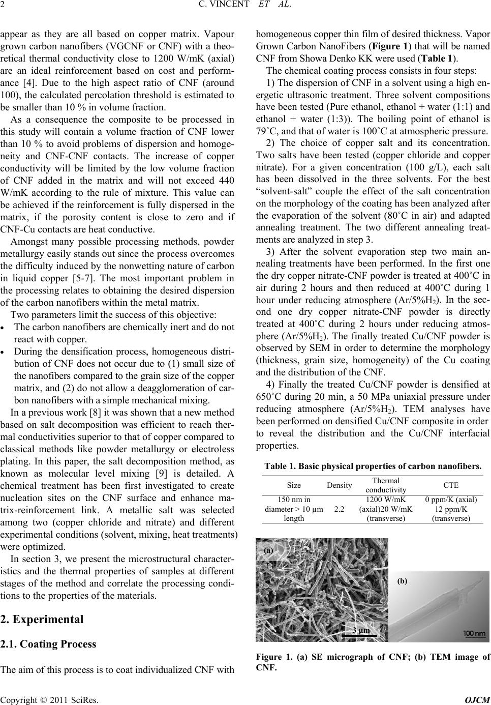
plete evaporation of the solvent. Figures 2(a) and (b)
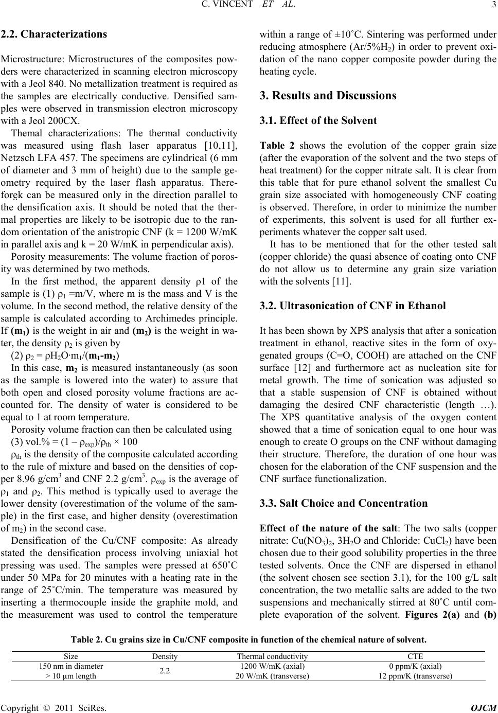
Table 2. Cu grains size in Cu/CNF composite in function of the chemical nature of solvent.
Size Density Thermal conductivity CTE
150 nm in diameter
> 10 µm length 2.2 1200 W/mK (axial)
20 W/mK (transverse)
0 ppm/K (axial)
12 ppm/K (transverse)