Journal of Transportation Technologies, 2011, 1, 102-106
doi:10.4236/jtts.2011.14013 Published Online October 2011 (http://www.SciRP.org/journal/jtts)
Copyright © 2011 SciRes. JTTS
High Efficiency LSM with High Flux Density
for Transportation
Nobuo Fujii1, Mitsunobu Terata1, Takeshi Mizuma2
1Faculty of Information Science and Electrical Engineering, Kyushu University, Fukuoka, Japan
2National Traffic S afety & Environment Laboratory, Tokyo, Japan
E-mail: fujii@ees.kyushu-u.ac.jp
Received May 17, 201 1; revised July 25, 2011; accepted August 27, 2011
Abstract
A new linear synchronous motor (LSM) with permanent magnet (PM) is proposed to develop a linear motor
for transportation with high efficiency. The LSM has very high air-gap flux density beyond the remanent
magnetization of rare earth PM, which is generated by a special field structure with rare earth PM. Two PMs
are arranged to form a triangle over each pole to concentrate the flux of PMs. The maximum value of air-gap
flux density is limited to the magnetic saturated value in the core of field and armature, respectively, which is
about 2T. The configuration is insusceptible to armature reaction because of large equivalent magnetic resis-
tance in the flux path. The characteristics are analyzed using a two-dimensional finite element method (FEM)
considering the core material. For high air-gap flux density and small armature reaction, the very high thrust
density beyond the conventional maximum value of 100kN/m2 can be obtained. Using normal thrust density
with small magneto-motive force (mmf) of armature, this LSM has efficiency and power factor that are as
high as or higher than a rotational motor.
Keywords: Permanent Magnet, Synchronous Motor, Linear Synchronous Motor, LSM, High flux Density,
High Efficiency, Linear Motor, Transportation
1. Introduction
Various kinds of linear synchronous motors (LSMs) have
been designed for new applications [1]. The characteris-
tics of LSM are basically similar to those of rotational
synchronous motor (SM). The amplitude of air-gap flux
density generated by the field of LSM for transportation
is generally not large because of large gap for safety. In
the case of low flux density in air-gap, the efficiency is
not good because the large magneto-motive force (mmf)
of armature winding is needed to obtain the required
thrust and it causes the large ohmic loss in a normal
conducting coil. It is often used Halbach array [2] to get
a large air-gap flux density by using rare earth permanent
magnet (PM), whose value is und er about 1T even in the
use of most strong PM.
We contrive a new field for LSM or SM to obtain the
higher air-gap flux density than the remanent magnetiza-
tion of rare earth PM [3]. In the paper, the characteristics
of LSM are analyzed by using a finite element method
(FEM). The influence of magnetic saturation and arma-
ture reaction is investigated respectively. The ripple of
thrust and normal force in the running are checked for
concentrated three-phase armature winding. The effi-
ciency and power factor are shown respectively.
2. Proposed PM LSM With High-Flux
Density
The fundamental structure of proposed LSM is shown in
Figure 1. This motor is quite different from IPM (inte-
rior permanent magnet)-SM in magnetic properties in
spite of similar appearance. Two PMs are arranged to
form a triangle over each pole to concentrate the flux of
PMs. The both ends of PM are set to the surface of
air-gap and the backside of magnetic field to be wide as
much as possible for the width of PM. The thickness of
yoke connected to N-pole and S-pole of field pole are
almost equal to the thickness of magnetic field to be hard
to the magnetic saturation. On the other hand, in the ar-
mature, the three-phase winding is the concentrated wind-
ing to be wide as much as possible in the width of tooth
and to be hard to the magnetic saturation in t he tooth.
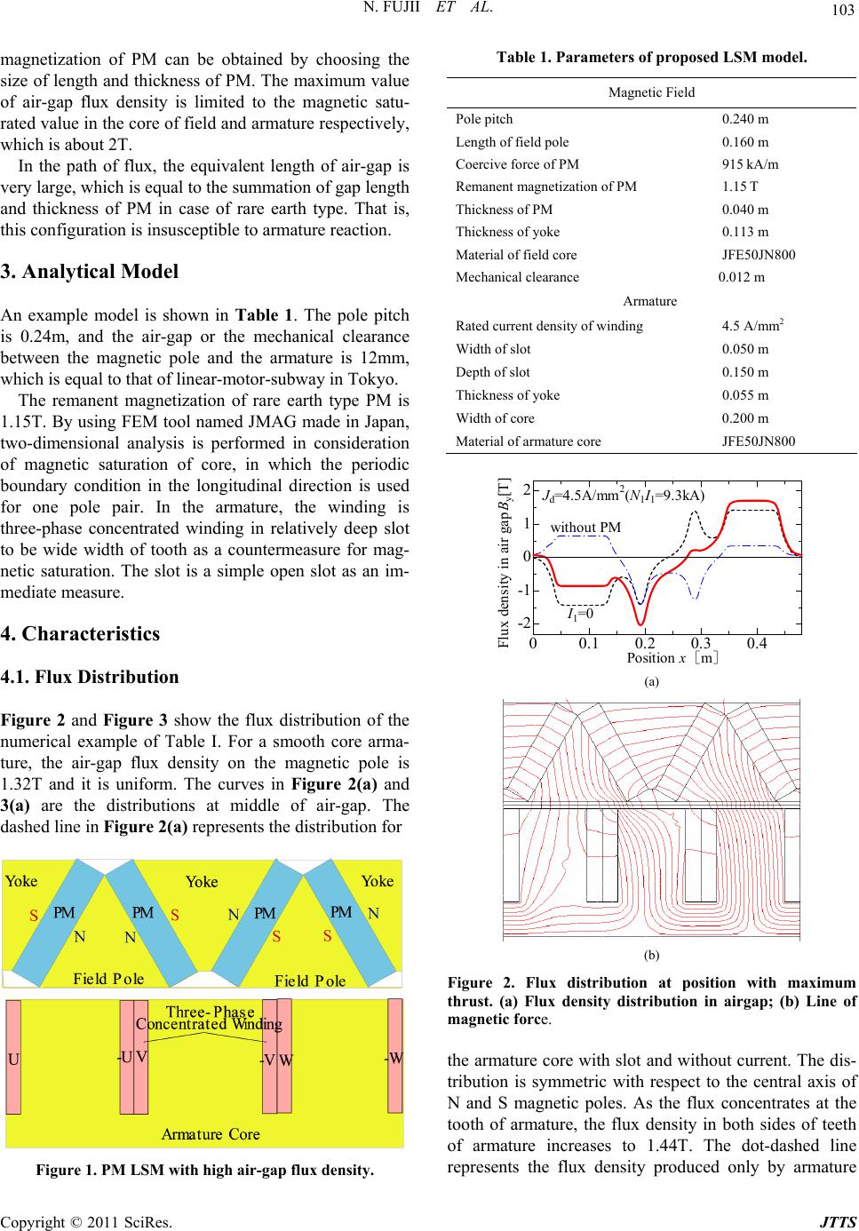
The higher air-gap flux density than the remanent
103
N. FUJII ET AL.
magnetization of PM can be obtained by choosing the
size of length and thickness of PM. The maximum value
of air-gap flux density is limited to the magnetic satu-
rated value in the core of field and armature respectiv ely,
which is about 2T.
In the path of flux, the equivalent length of air-gap is
very large, which is equal to the summation of gap length
and thickness of PM in case of rare earth type. That is,
this configuration is insusceptible to armature reaction.
3. Analytical Model
An example model is shown in Table 1. The pole pitch
is 0.24m, and the air-gap or the mechanical clearance
between the magnetic pole and the armature is 12mm,
which is equal to that of linear-motor-subway in Tokyo.
The remanent magnetization of rare earth type PM is
1.15T. By using FEM tool named JMAG made in Japan,
two-dimensional analysis is performed in consideration
of magnetic saturation of core, in which the periodic
boundary condition in the longitudinal direction is used
for one pole pair. In the armature, the winding is
three-phase concentrated winding in relatively deep slot
to be wide width of tooth as a countermeasure for mag-
netic saturation. The slot is a simple open slot as an im-
mediate measure.
4. Characteristics
4.1. Flux Distribution
Figure 2 and Figure 3 show the flux distribution of the
numerical example of Table I. For a smooth core arma-
ture, the air-gap flux density on the magnetic pole is
1.32T and it is uniform. The curves in Figure 2(a) and
3(a) are the distributions at middle of air-gap. The
dashed line in Figure 2(a) represents the distribut i o n f or
Figure 1. PM LSM with high air-gap flux density.
Table 1. Parameters of proposed LSM model.
Magnetic Field
Pole pitch 0.240 m
Length of field pole 0.160 m
Coercive force of PM 915 kA/m
Remanent magnetization of PM 1.15 T
Thickness of PM 0.040 m
Thickness of yoke 0.113 m
Material of field core JFE50JN800
Mechanical clearance 0.012 m
Armature
Rated current density of winding 4.5 A/mm2
Width of slot 0.050 m
Depth of slot 0.150 m
Thickness of yoke 0.055 m
Width of core 0.200 m
Material of armature core JFE50JN800
00.1 0.2 0.3 0. 4
-2
-1
0
1
2
Position xm
Flux density in air gap B
y
[T]
I
1
=0
J
d
=4.5A/mm
2
(N
1
I
1
=9.3kA)
without PM
(a)
(b)
Figure 2. Flux distribution at position with maximum
thrust. (a) Flux density distribution in airgap; (b) Line of
magnetic force.
the armature core with slot and withou t current. The dis-
tribution is symmetric with respect to the central axis of
N and S magnetic poles. As the flux concentrates at the
tooth of armature, the flux density in both sides of teeth
of armature increases to 1.44T. The dot-dashed line
represents the flux density produced only by armature
Copyright © 2011 SciRes. JTTS
N. FUJII ET AL.
104
winding at the rated current, whose phase is adjusted to
obtain the maximum thrust in this spatial arrangement.
The bold solid line represents the distribution of LSM.
Figure 2(b) shows the corresponding magnetic flu x lines
of solid lin e in Figure 2(a). The flux density in the yoke
of field is not high in this structure. The magn etic satura-
tion occurs only in the small overlap region between the
field pole and the tooth of armature.
The flux distribution at different positional relation be-
tween the field and the armature is shown in Figure 3. The
thrust at the position is minimum in variation of thrust.
4.2 Force Characteristics
The thrust, which corresponds to the torque in the rota-
tional motor, is varied for the phase of armature current
and the spatial relation between the field and the arma-
ture. The optimum phase for maximum thrust is defined
as o
in the case shown in Figure 2. When the mmf of
armature winding is varied, the optimum phase is defined
to be oo
 here. Figure 4 shows the phase. In the
following thrust and normal force, the phase in Figure 4
is used.
The thrust of one-pole-pair length as functions of mmf
of armature winding is shown in Figure 5. When the
thrust density is defined as the thrust per the area of air-
gap region, 9.6 kN corresponds to the thrust density
00.1 0.20.3 0.4
-2
-1
0
1
2
Position xm
Flux density in air gap By[T]
I1=0
Jd=4. 5 A/mm 2(N1I1=9 . 3kA)
without PM
(a)
(b)
Figure 3. Flux distribution at different position. (a) Flux
density distribution in airgap; (b) Line of magnetic force.
of 100 kN/m2, which is about the highest value in all
type of motors included rotational motor. The value of
100kN/m2 is achieved by HD motor [4], which is a type
of stepping motor using PM with very small air-gap. In
Figure 5, the influence of magnetic saturation as in-
crease of armature mmf is very small. This LSM can
generate larger thrust easily by increasing the armature
mmf considering the current density, which is adjusted
by the depth of slot.
Figure 6 shows the ripple of thrust. The rate of ripple
for average is within 5.4
%, which is not large. Al-
though the thrust ripple in app lication of transportatio n is
not a serious problem because of very large inertia, the
ripple will decrease by a design of slot shape if necessary.
2 4 6 810
-20
-10
0
Ampare-turns of armature winding
N
1
I
1
[kA]
Optimum pha se

o
[deg.]
Figure 4. Phase for maximum thrust.
510
4
8
12012345
0
Width of 0.2m
Ampare-turns of armature winding N
1
I
1
[kA]
Thrust
F
x
[kN ]
Current density of armature winding J
d
[A/mm
2
]
Figure 5. Thrust curve as functions of current.
0.01 0.02 0.03
4
8
12
0
Time t [s]
Thrust F
x
[k N]
v=15m/s
f=31.25Hz
J
d
=4 .5 A/ mm
2
Figure 6. Ripple of thrust in running.
Copyright © 2011 SciRes. JTTS
105
N. FUJII ET AL.
The normal force means the attractive force between
the field and the armature. The normal force is very large
because of large air-gap flux density, as shown in Figure
7. The normal force decreases slightly as armature mmf
increases. This means that the influence of armature mmf
is small. Figure 8 shows the ripple of normal force. The
ripple rate is within %. This large attractive normal
force will be able to use as a force to reduce the vehicle
weight by the method like that using in M-BAHN [5].
2.3
4.3. Voltage and Current
Figure 9 shows the phase voltage of armature winding as
functions of armature mmf. The increase with mmf is
small, that is, the characteristics also mean that the in-
fluence of armature mmf on the air-gap flux density is
small.
510
20
40
60
0
Width of 0.2m
Normal (att rac ti ve) fo rce F
y
(kN)
Ampare-turns of armature winding N
1
I
1
[kA]
Figure 7. Normal force curve as functions of current.
0.01 0.02 0.03
20
40
60
0
Time t [s]
Normal fo rce F
y
[kN ]
v=15m/s
f=31.25Hz
J
d
=4.5A/mm
2
Figure 8. Ripple of normal force in running.
05 10
0
100
200
300
400
Ampare-turns of armature winding N
1
I
1
[kA]
Primary voltage V
1
[V]
v=15m/s
v=5m/s
Figure 9. Phase voltage curves as functions of current.
Figure 10 shows the wave form of current when the
sinusoidal wave voltage is supplied. The phase differ-
ence between voltage and c u r rent is sma l l.
4.4. Power Factor and Efficiency
The power factor and the efficiency versus thrust vary
with a drive control method. The maximum thrust con-
trol for given current is adopted here. The power factor
cos
shown in Figure 11 is calculated as the following,
as the wave form of voltage is not sinusoidal for sinu-
soida l current.

2
0
22
0
1()()
2
cos 1
2
RMS
vtit dt
I
vtdt
(1)
where
R
MS
I
means the root-mean-square value of current.
That is, the power factor is included the influence of dis-
tortion of wave form. On the power factor of LSM, the
variation by speed or frequency is small. Although the
value decreases rapidly as the thrust increases, the over-
all value is high. The thrust of LSM corresponding to the
thrust density of normal rotational motor of 20 kN/m2 -
40 kN/m2 is 1.92 kN - 3.84 kN. For the region of thrust,
the power factor is over 0.98 on this two-dimensional
analysis neglecting the inductance of coil end.
180 360
-300
-200
-100
100
200
300
0
Electrical ang le [deg . ]
Votage [V x2]
Current [A ]
Voltage at 15m/s
Voltage at 5m/s
Current at 15 m/s
Current at 5m/s
Figure 10. Wave forms of phase voltage and current.
0246810
0.8
0.9
1
Thrust F
x
[kN]
Pow er factor cos
5m/s
15m/s
Width of 0.2m
Figure 11. Power factor curve as functions of thrust.
Copyright © 2011 SciRes. JTTS
N. FUJII ET AL.
Copyright © 2011 SciRes. JTTS
106
0 2 4 6 810
0.8
0.9
1
Thrust F
x
[kN]
Efficiency
5m/s
15m/s
Width of 0.2m
Figure 12. Efficiency curve as functions of thrust.
0246810
0.8
0.9
1
Thrust F
x
[kN]
Efficiency
Equal length
Double length
v=1 5m/ s
Figure 13. Efficiency for sec t ion le ngth of power supply.
Figure 12 shows the efficiency, in which the only
ohmic loss of armature winding is considered and the
iron loss in both cores is neglected. Even in the low
speed of 5 m/s, the efficiency is over 0.94.
In a ground primary type of LSM, the switching of
armature winding on the guide way is needed . In Figure
12, the length of armature is assumed to be equal to that
of field. The double length in Figure 13 means that the
supplied section length is twice as long as that of field.
The resistance of winding is estimated on the three-di-
mensional model. The efficiency of this LSM is very
high which breaks a conventional belief in the linear
motor. In practical application of transportation, this
LSM will can operate at normal thrust density of 20
kN/m2 – 40 kN/m2, that is 1.92 kN - 3.84 k N of the LSM,
meeting the demanded thru st easily.
5. Conclusions
1) The simple structure of field of synchronous motor
to obtain high air-gap flux density even in a motor with
large air-gap is shown.
2) The air-gap flux density b eyond the remanent mag-
netic flux density of rare earth PM is realized easily.
3) For high air-gap flux density and small armature
reaction, the very high thr ust density beyond th e conven-
tional maximum value of 100kN/m2 can be obtained.
4) In the use in normal thrust density with small mmf
of armature, the very high efficiency and power factor
are realized, although the results are obtained by simple
analysis. This LSM has the potential that the value of
efficiency breaks a conventional belief in the linear mo-
tor for transportation.
6. References
[1] J. F. Gieras and Z. J. Piech, “Linear Synchronous Motors,
Transportation and Automation Systems,” CRC Press,
2000.
[2] K. Halbach, “Design of Permanent Multipole Magnets
with Oriented Rare Earth Cobalt Material,” Nuclear In-
struments and Methods, Vol. 169, 1980, pp.1-10.
doi:10.1016/0029-554X(80)90094-4
[3] N. Fujii, T. Mizuma and M. Terata, “Linear Synchronous
Motor with High Flux Density,” IEEJ Transmission, Vol.
131-D, No. 3, 2011, pp. 412-413.
doi:10.1541/ieejias.131.412
[4] M. Karita, “High Thrust type HD Linear Motor,” The
Japan Society of Mechanical Engineers, Vol. 101, No.
950, 1998, p. 68.
[5] K. Dreimann, “The M-BAHN Maglev Rapid Transit
System-Technology, Status, Experience,” International
Conference on MAGLEV AND LINEAR DRIVES, Las
Vegas, May 1987, pp. 113-118.