Paper Menu >>
Journal Menu >>
 Journal of Transportation Technologies, 2011, 1, 94-101 doi:10.4236/jtts.2011.14012 Published Online October 2011 (http://www.SciRP.org/journal/jtts) Copyright © 2011 SciRes. JTTS Transformer Characteristics of Linear Motor-Transformer Apparatus Nobuo Fujii1, Shuhei Kanamitsu1, Takeshi Mizuma2 1Faculty of Information Science and Electrical Engineering, Kyushu University, Fukuoka, Japan 2National Traffic S afety & Environment Laboratory, Tokyo, Japan E-mail: fujii@ees.kyushu-u.ac.jp Received May 17, 201 1; revised July 12, 2011; accepted August 20, 2011 Abstract The characteristics of linear transformer are studied analytically. The transformer is composed in one of modes of linear motor-transformer apparatus proposed for future wireless light rail vehicle (LRV). The sec- ondary (onboard) power factor can be adjusted at any value by an onboard converter. The equivalent circuit is used to study the transferred power control. The parameters are determined by three-dimensional finite element method (FEM) analysis for one pole-pair model. Under the rated primary (input) and secondary vol- tage and current, which are specified for linear motor operation, the characteristics of the secondary power factor are cleared. It is also shown that the input capacitor can improve the primary power factor and de- crease the input power capacity, but does not change the efficiency. This linear transformer has the effi- ciency of 91% and the input power factor of 0.87 when the apparatus without input capacitor is controlled at the secondary power factor of 0.4. Keywords: Linear Motor, LIM, Linear Transformer, Non-Contact Power Collection, Wireless LRV, FEM, Finite Element Method, Power Factor, Equivalent Circuit 1. Introduction New type of public transportation which is in harmony with environment has been hoped for a future urban transit system [1-3]. We have proposed the linear mo- tor-transformer apparatus for overhead-wireless and non-contact power collection of light rail vehicle (LRV), which has functions the secondary current controlled linear induction motor and linear transformer [2,3]. The transformer and linear motor mode respectively can be switched by only the signal of onboard converter, as shown in Figure 1. The transformer mode with out thrust is used for non-contact charge to onboard battery in standstill at station. The charging power and the secon- dary power factor respectively can be controlled by on- board converter. In the paper, the power supply characteristics of transformer are studied analytically. The equivalent cir- cuit of transformer is used to compute the characteristics. The parameters in equivalent circuit are obtained by the analysis using the three-dimensional finite element me- thod (FEM). On this transformer, the desirable primary power factor can be obtained by control the amplitude and phase of secondary voltage and current.As functions of secondary power factor, therefore, the characteristics of primary power factor and efficiency are cleared under the limit of primary voltage, primary current and secon- dary current. The effect of serially or parallel connected input capacitor to obtain a unity power factor at primary side is also studied. 2. Analytical Model Figure 1 shows configuration for each operating mode. For economical configuration, the primary winding on ground is the concentrated single-phase winding supplied by commercial pow er source. The secondary winding on board is a double-layer distributed winding with hex- agonal shape in the end winding. The onboard converter operates as a rectifier for the transformer with sin- gle-phase and as a two-phase inverter for the linear mo- tor respectively. Figure 1(a) shows the formation of lin- ear transformer with single phase primary-single phase secondary configuration, in which the thrust does not generate at the position. The model with numerical v alue for one pole-pair length is shown in Figure 2. The rated 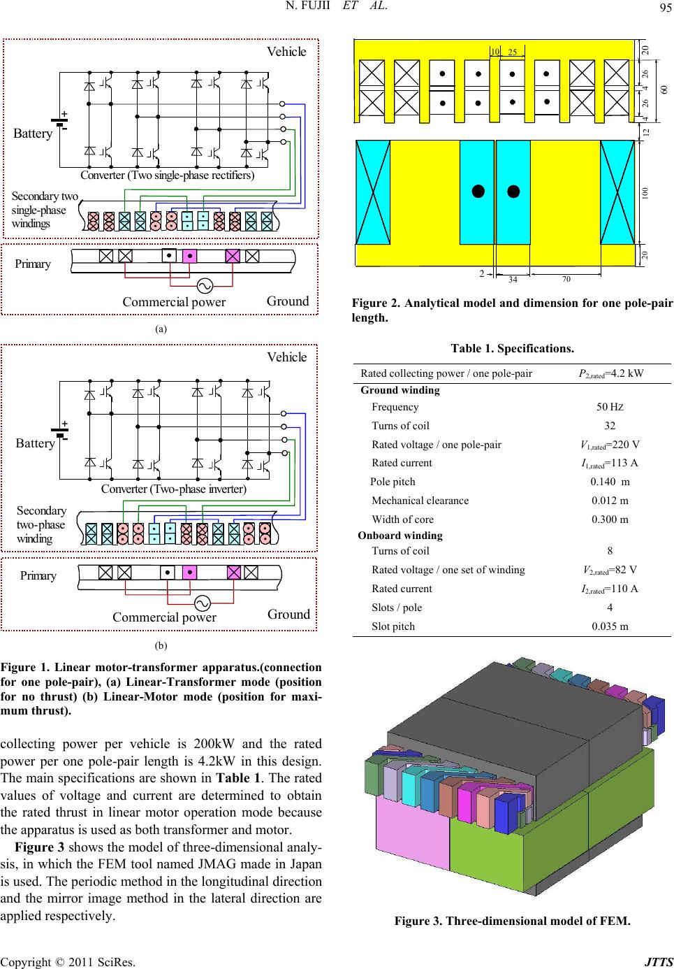 95 N. FUJII ET AL. Secondary two s i ngle-phase windings + - Battery C onve rter (T w o single-p hase rectifiers) Ground Primary Vehicle Commercial power (a) + - Battery Secondary two-p hase winding Primary Converter (Two-phase inverter) Vehi cle Ground Commercial power (b) Figure 1. Linear motor-transformer apparatus.(connection for one pole-pair), (a) Linear-Transformer mode (position for no thrust) (b) Linear-Motor mode (position for maxi- mum thrust). collecting power per vehicle is 200kW and the rated power per one pole-pair length is 4.2kW in this design. The main specifications are shown in Table 1. The rated values of voltage and current are determined to obtain the rated thrust in linear motor operation mode because the apparatus is used as both transformer and motor. Figure 3 shows the model of three-dimensional analy- sis, in which the FEM tool named JMAG made in Japan is used. The periodic method in the longitudinal direction and the mirror image method in the lateral direction are applied respectively. 10 25 20 60 26 100 20 70 34 2 4 12 426 Figure 2. Analytical model and dimension for one pole-pair length. Table 1. Specifications. Rated collecting power / one pole-pair P2,rated=4.2 kW Ground winding Frequency 50 HZ Turns of coil 32 Rated voltage / one pole-pair V1,rated=220 V Rated current I1,rated=113 A Pole pitch 0.140 m Mechanical clearance 0.012 m Width of core 0.300 m Onboard winding Turns of coil 8 Rated voltage / one set of winding V2,rated=82 V Rated current I2,rated=110 A Slots / pole 4 Slot pitch 0.035 m Figure 3. Three-dimensional model of FEM. Copyright © 2011 SciRes. JTTS  N. FUJII ET AL. 96 3. Equivalent Circuit The equivalent circu it of this transformer is expressed as shown in Figure 4. The values of element parameters can be estimated by using FEM analysis [4]. The basic electrical circuit can be modified to the machinery equivalent circuit with the leakage inductances, the ex- citing inductance and the special corrected inductance respectively [4]. Although the expression is intelligible, it is difficult to estimate the equivalent turn ratio of pri- mary to secondary exactly, as shown later in Figure 5. Therefore, in the following study, the equivalent circuit of Figure 4 is used, and the values of elements are dealt with constant values. When the primary and secondary members are in the position of Figure 2 and the each secondary current is controlled in the same manner, M1,a = M1,b and L2,a = L2,b. The values of constants obtained by three-dimen- sional FEM are shown in Table 2. Figure 5 shows the ratio of primary to secondary on voltage and current. These ratios are not constant and considerably different from the turn ratio of windings. b M,1 1 r 1 L 1 I a L,2 b I,2 a V,2 b L,2 2 r 2 M a M,1a I,2 b V,2 Primary Secondary 1 V 2 r Figure 4. Equivalent circuit for electrical circuit. Table 2. Values of constants. Resistance of primary win din g (11 ) 5 C1 r 0.02357 Resistance of secondary winding (11 ) 5 C2 r 0.01556 Reactance of primary winding 1 L 1.9678 Reactance of secondary winding 2 L 0.4404 Mutual reactance between primary and secondary 1 M 0.4666 Mutual reactance between secondary and secondary 2 M 0.0718 0.2 0.4 0.6 0.8 1 2 4 6 8 0 Ratio of primary to secondary voltage V 1 /V 2 Secon dary power factor cos 2 I 2 =110A P 2 =4. 2kW 50A 90A (a) 0.2 0.4 0.6 0.8 1 2 4 6 8 0Secondary power factor cos 2 I 2 =50A Ratio of primary current to secondary current I 1 /I 2 P 2 =4.2kW 110A 90A (b) Figure 5. Ratio of voltage and current between primary and secondary, (a) Voltage (b) Current. 4. Characteristics In the following, the condition of rated collection power of 4.2 kW is dealt with M1,a = M1,b = M1, L2,a = L2,b = L2, I2a = I2b = I2 and V2a = V2b = V2 . On this transformer, the converter is used to control the power for charge and to obtain the desirable primary power factor by control the secondary power factor. Al- though the primary voltage is fixed in practical use, it is hard to consider the fixed voltage in this stage because the relation between primary and secondary voltage changes as shown in Figure 5. The secondary power factor controlled by the converter is, therefore, used as a parameter to clear the characteristics of this type of transformer. Figure 6 denotes the secondary voltage curves as functions of secondary power factor at the rated secon- dary power. It is examined on the rated current of 110A, 90A and 50A as the secondary current. The secondary voltage incr eases as secondary pow er factor or seco ndar y current decreases. As the secondary voltage is limited under the rated voltage of 82 V which is determined in linear motor operation, the secondary power factor must be over 0.23 at the rated secondary current. When the secondary current is smaller, the secondary voltage in- creases under the constant output of 4.2 kW, and the us- able region of secondary power factor becomes narrow. Figure 7 shows the primary voltage-secondary power factor characteristics. The primary voltage is not propor- Copyright © 2011 SciRes. JTTS  97 N. FUJII ET AL. tion to the secondary voltage. This is much different from conventional transformer. On the rated secondary current, the primary voltage decreases as secondary power factor decreases in the power factor range higher than 0.5. As the primary voltage is also limited to the rated value of 220 V, the usable region of secondary power factor is over 0.23. Figure 8 represents the primary current characteristics. The primary current increases as the secondary current increases at secondary power factor of 1.0. On the other hand, th e primar y current decr eases as second ary current increases in the region of secondary power factor of 0.3. This figure shows that the usable region of secondary power factor is from 0.18 to 0.92 on the condition of rated primary current. From Figures 6-8, the usable region of secondary power factor for control is determined to be from 0.23 to 0.92 from total conditions of rated primary voltage, cur- rent and second ary voltage. 0.2 0.4 0.6 0.81 50 100 150 200 0 Secondary power factor cos 2 I 2 =110A Secondary voltage V 2 [V] P 2 =4.2kW 50A 90A V 2.rated Figure 6. Secondary current—secondary power factor curves. 0.2 0.4 0.6 0.8 1 100 200 300 400 0 Primary voltage V 1 [V] Secondary power factor cos 2 I 2 =110A P 2 =4.2kW 50A 90A V 1, r ated Figure 7. Primary voltage—secondary power factor curves. Figure 9 denotes the primary power factor character- istics as functions of secondary power factor. When the secondary power factor is controlled to be 1.0, the pri- mary power factor is very low for any secondary current because the magnetic coupling between primary and secondary member is weak for large air gap. At the rated secondary current, the primary power factor increases as secondary power factor decreases in the region of sec- ondary power factor bet w een 0.4 and 1. 0 . The extreme value of primary power factor increases as the secondary current increases. The maximum pri- mary power factor can be 0.87 at the secondary power factor of 0.4 for the rated secondary current. Figure 10 shows the curves of input capacity as func- tions of secondary power factor. The minimum capacity is small as the secondary current is large. The rated sec- ondary current of 110 A and the about secondary power factor of 0.4 gives the minimum capacity. When the secondary power factor is controlled to be 1.0, the input capacity is about four times larger than the minimum value. 0.2 0.4 0.6 0.8 1 50 100 150 200 0Secondary power factor cos 2 I 2 =110A Primary curr en t I 1 [A] P 2 =4.2kW 50A 90A I 1, r ated Figure 8. Primary current—secondary power factor curves. 0.2 0.4 0.6 0.81 0.2 0.4 0.6 0.8 1 0 Primary p o w er factor co s 1 Secondary power factor cos 2 I 2 =110A P 2 =4.2kW 50A 90A Figure 9. Primary power factor—secondary power factor curves. Copyright © 2011 SciRes. JTTS  N. FUJII ET AL. 98 Figure 11 shows the efficiency characteristics, which is computed taking into consideration of only copper loss in the primary and secondary windings. For the rated secondary current of 110 A, in which the current density is 2.21A/mm2, the efficiency is 91% when the secondary power factor is 0.4. Figure 12 represents the ratio between primary and secondary copper loss. These losses have influence di- rectly on the efficiency. The current densities of primary and secondary winding are 2.00 A/mm2 and 2.21 A/mm2 respectively at rated current. When the secondary current is the rated value of 110A, the ratio of secondary loss to primary loss increase sharply as the secondary power factor becomes smaller than 1, and the ratio is 5.7 at secondary power factor of 0.4. As the influence of sec- ondary resistance is largely on the efficiency, the smaller secondary current density will bring higher efficiency. 5. Effect of Input Capacity In the following, the effect of input capacitor is studied to improve the input capacity. The cap acitor is connected in series or parallel at the input side of linear transfo rmer, as shown in Figure 13. In these cases, the input capacity S1 is defined as V1I1 and the primary power factor is de- fined as the ratio of input effective power to input ap- parent power of V1I1. 5.1. Serial Capacitor Figure 14 shows the primary power factor curves as functions of capacitance in series connected input ca- pacitor when the output power is the rated value and the secondary power factor is kept at unity. The capacitance with primary power factor of unity depends on value of secondary current. In the following section, the cap acitor with capacitance of 2.61mF for the rated secondary cur- rent of 110 A, 2.43 mF for I2=90 A and 1.83mF for I2=50 A are used respectively for both primary and secondary power factor of unity at the rated output power. 0.2 0.4 0.6 0.8 1 10 20 30 40 0 Primary apparent powe r S 1 [kVA] Secondary po we r factor cos 2 I 2 =110A P 2 =4.2kW 50A90A Figure 10. Primary apparent power—secondary power factor curves. 0.2 0.4 0.6 0.8 1 0.2 0.4 0.6 0.8 1 0 Efficiency Sec on dary po wer fac tor cos 2 I 2 =110A P 2 =4.2kW 50A 90A Figure 11. Efficiency—secondary power factor curves. 0.2 0.4 0.6 0.81 1 2 3 4 5 6 7 8 0 Loss ratio of secondary to primary P 2L /P 1L Secondary power factor cos 2 I 2 =110A P 2 =4.2kW 50A 90A P 2L =P 1L Figure 12. Ratio of secondary loss to primary loss—second- dary power factor curves. 1 r 1 L 2 L2 V 2 r 2 M 1 M 2 I Primary Secondar y L1 V 2 r C 1 I 1 V 2 I 2 V 2 L 1 M (a) 1 r 1 L L I1 2 r 2 M Primary Secondary 1 V 2 r C 1 I 1 M 1 M 2 L 2 L 2 I 2 I 2 V 2 V (b) Figure 13. Model with input capacitor, (a) Serial capacitor, (b) Parallel capacitor. Copyright © 2011 SciRes. JTTS 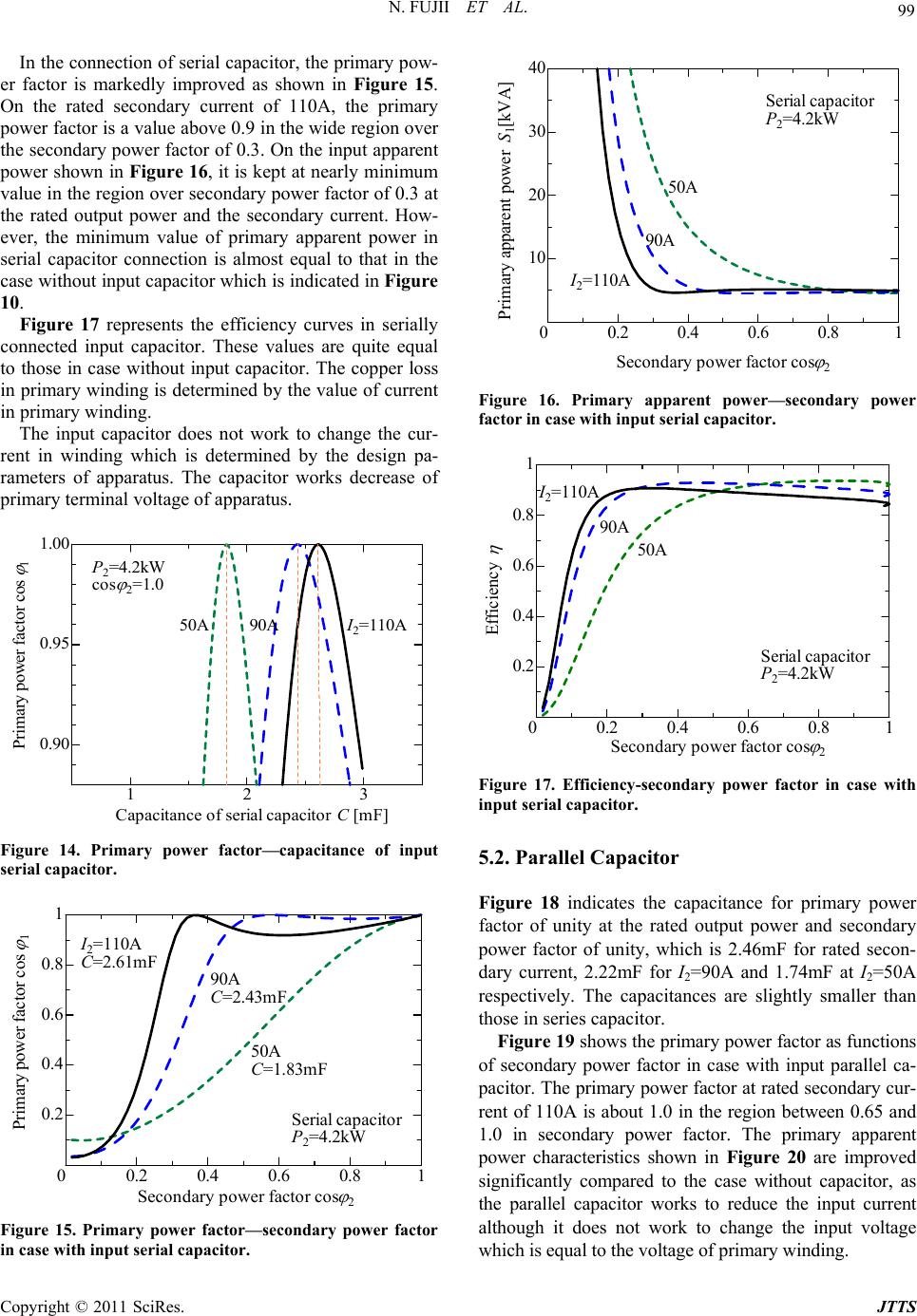 99 N. FUJII ET AL. In the connection of serial capacitor, the primary pow- er factor is markedly improved as shown in Figure 15. On the rated secondary current of 110A, the primary power factor is a value above 0.9 in the wide region over the secondary power factor of 0.3. On the input apparent power shown in Figure 16, it is kept at nearly minimum value in the region over secondary power factor of 0.3 at the rated output power and the secondary current. How- ever, the minimum value of primary apparent power in serial capacitor connection is almost equal to that in the case without input capacitor which is indicated in Figure 10. Figure 17 represents the efficiency curves in serially connected input capacitor. These values are quite equal to those in case without input capacitor. The copper loss in primary winding is determined by the value of curren t in primary winding . The input capacitor does not work to change the cur- rent in winding which is determined by the design pa- rameters of apparatus. The capacitor works decrease of primary terminal voltage of apparatus. 123 0.90 0.95 1.00 I 2 =110A Primary power factor cos 1 Capacitance of serial capacitor C [m F] P 2 =4.2kW co s 2 =1.0 50A 90A Figure 14. Primary power factor—capacitance of input serial capacitor. 0.2 0.4 0.6 0.81 0.2 0.4 0.6 0.8 1 0 Prim ar y p ower f actor cos 1 Seconda ry power fac tor cos 2 I 2 =110A C=2.61mF Serial capacitor P 2 =4.2kW 50A C=1.83mF 90A C=2.43mF Figure 15. Primary power factor—secondary power factor in case with input serial capacitor. 0.2 0.4 0.6 0.8 1 10 20 30 40 0 Primary apparent power S 1 [kVA] Sec ondary power fac tor cos 2 I 2 =110A Seria l ca pacitor P 2 =4.2kW 50A 90A Figure 16. Primary apparent power—secondary power factor in case with input serial capacitor. 0.2 0.4 0.60.8 1 0.2 0.4 0.6 0.8 1 0 Efficiency Secondary power factor cos 2 I 2 =110A Serial capacitor P 2 =4.2kW 90A 50A Figure 17. Efficiency-secondary power factor in case with input serial capacitor. 5.2. Parallel Capacitor Figure 18 indicates the capacitance for primary power factor of unity at the rated output power and secondary power factor of unity, which is 2.46mF for rated secon- dary current, 2.22mF for I2=90A and 1.74mF at I2=50A respectively. The capacitances are slightly smaller than those in series capacitor. Figure 19 shows the primary power factor as functions of secondary power factor in case with input parallel ca- pacitor. The primary power factor at rated secondary cur- rent of 110A is about 1.0 in the region between 0.65 and 1.0 in secondary power factor. The primary apparent power characteristics shown in Figure 20 are improved significantly compared to the case without capacitor, as the parallel capacitor works to reduce the input current although it does not work to change the input voltage which is equal t o the vol t age of primary wi ndi ng. Copyright © 2011 SciRes. JTTS  N. FUJII ET AL. 100 123 0.90 0.95 1.00 I 2 =110A Primary p o wer factor co s 1 Capacitance of parallel capacitor C [mF] P 2 =4.2kW cos 2 =1.0 50A 90A Figure 18. Primary power factor—capacitance of input parallel capacitor. 0.2 0.4 0.6 0.81 0.2 0.4 0.6 0.8 1 0 Primary power factor cos 1 Secondary power factor cos 2 I 2 =110A C=2.46mF Parallel capaci tor P 2 =4.2kW 50A C=1.74mF 90A C=2.22mF Figure 19. Primary power factor—secondary power factor in case with input parallel capacitor. 0.2 0.4 0.6 0.81 10 20 30 40 0 Primary apparent power S 1 [kVA] Secondary pow er factor cos 2 I 2 =110A Parallel capacitor P 2 =4.2kW 50A 90A Figure 20. Primary apparent power—secondary power factor in case with input parallel capacitor. The efficiency characteristics do not change on com- paring those without capacitor because neither the cur- rent of I1L in Figure 13(b) nor the primary loss is changed by the input capacitor. 5.3. Comparison Figure 21 shows the comparison of input apparent power among in cases wit h seri al capacitor, paral lel capacit or and without capacitor. On the region of second- dary power factor with minimum valu e of primary ap- parent power, the region of serial capacitor is wide com- pared with that of parallel capacitor. The minimum value in case without capacitor is almost equal to that in case of serial or parallel capacitor although the value is ob- tained at the limited secondary power factor of about 0.4. In this apparatus, the u sable region of secondary po wer factor is over 0.23, which is obtained from the condition of rated primary voltage, current and secondary voltag e for linear motor operation. Figure 22 indicates the capacity for serial capacitor compared to that for parallel capacitor in the condition rated secondary current with optimum capacitance for input power factor. Considering the capacity and the us- able region of secondary power factor, the serial capaci- tor will be better than parallel capacitor. However, the improvement of the apparent input power is not signify- cant in the region between secondary power factor of 0.3 and 0.4, as shown in Figure 21. 0.2 0.4 0.6 0.81 10 20 30 40 0 Primary apparent power S 1 [kVA] Secondary power factor cos 2 P 2 =4.2kW I 2 =110A Parallel capacitor Serial capacitor Without capacitor Figure 21. Input apparent power in cases with serial capaci- tor, parallel capacitor and without cap acitor respectively. 0.2 0.4 0.6 0.8 1 10 20 30 40 0 Ca p a city of capa c ito r S C [kVA] Sec ondary powe r fact or cos 2 P 2 =4.2kW I 2 =110A Para llel cap acito r Serial capacitor Figure 22. Capacity curves of input capacitor—secondary power factor . Copyright © 2011 SciRes. JTTS 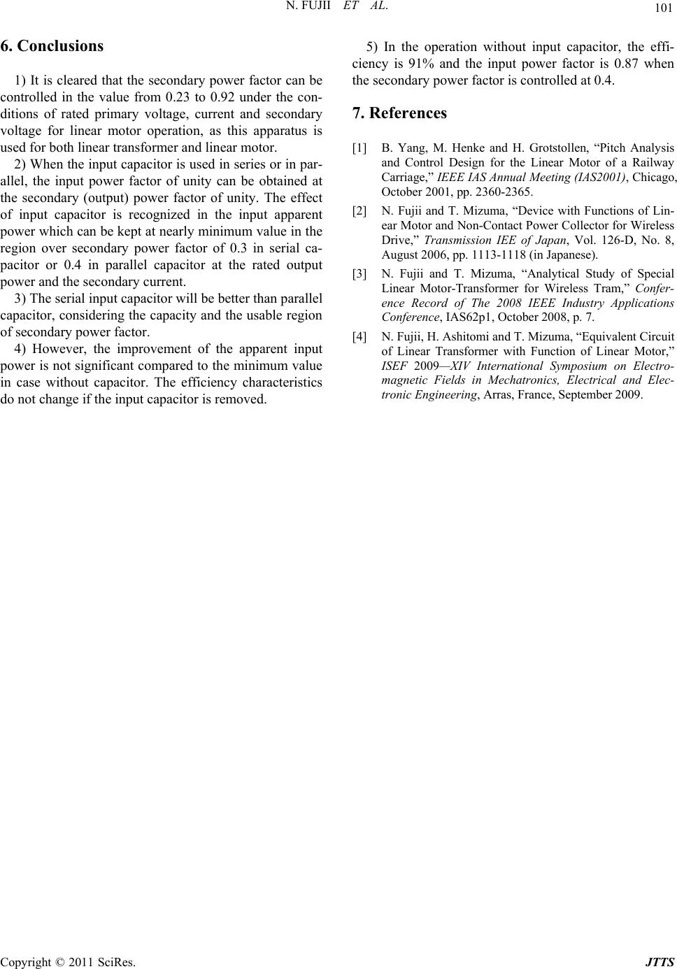 N. FUJII ET AL. Copyright © 2011 SciRes. JTTS 101 6. Conclusions 1) It is cleared that the secondary power factor can be controlled in the value from 0.23 to 0.92 under the con- ditions of rated primary voltage, current and secondary voltage for linear motor operation, as this apparatus is used for both linear transfo rmer and linear motor. 2) When the input capacitor is used in series or in par- allel, the input power factor of unity can be obtained at the secondary (output) power factor of unity. The effect of input capacitor is recognized in the input apparent power which can be kept at nearly minimum value in the region over secondary power factor of 0.3 in serial ca- pacitor or 0.4 in parallel capacitor at the rated output power and the secondary current. 3) The serial input capacitor will be better than parallel capacitor, considering the capacity and the usable region of secondary power factor. 4) However, the improvement of the apparent input power is not significant compared to the minimum value in case without capacitor. The efficiency characteristics do not change if the input capacitor is removed. 5) In the operation without input capacitor, the effi- ciency is 91% and the input power factor is 0.87 when the secondary power factor is controlled at 0.4. 7. References [1] B. Yang, M. Henke and H. Grotstollen, “Pitch Analysis and Control Design for the Linear Motor of a Railway Carriage,” IEEE IAS Annual Meeting (IAS2001), Chicago, October 2001, pp. 2360-2365. [2] N. Fujii and T. Mizuma, “Device with Functions of Lin- ear Motor and Non-Contact Power Collector for Wireless Drive,” Transmission IEE of Japan, Vol. 126-D, No. 8, August 2006, pp. 1113-1118 (in Japanese). [3] N. Fujii and T. Mizuma, “Analytical Study of Special Linear Motor-Transformer for Wireless Tram,” Confer- ence Record of The 2008 IEEE Industry Applications Conference, IAS62p1, October 2008, p. 7. [4] N. Fujii, H. Ashitomi and T. Mizuma, “Equivalent Circuit of Linear Transformer with Function of Linear Motor,” ISEF 2009—XIV International Symposium on Electro- magnetic Fields in Mechatronics, Electrical and Elec- tronic Engineering, Arras, France, September 2009. |