Engineering
Vol.4 No.12(2012), Article ID:25859,4 pages DOI:10.4236/eng.2012.412113
Development and Assessment of Thermoacoustic Generators Operating by Waste Heat from Cooking Stove
1Department of Mechanical, Materials and Manufacturing Engineering, The University of Nottingham in Malaysia, Semenyih, Malaysia
2Faculty of Engineering, The University of Nottingham, Nottingham, UK
Email: keyx9bce@nottingham.edu.my
Received August 24, 2012; revised September 22, 2012; accepted October 1, 2012
Keywords: Cooking Stove; Electricity; Thermoacoustic Engine; Waste Heat
ABSTRACT
This paper presents the development and assessment of two low-cost, travelling wave, thermoacoustic generators operating by waste heat energy from cooking stove. One powered by waste heat from a propane-driven stove, the other powered by waste heat from a wood-burning stove. The propane-driven thermoacoustic generator was successfully demonstrated to produce approximately 15 watts of electricity using a commercial audio loudspeaker. The wood-burning thermoacoustic generator was successfully constructed and tested to generate a maximum of 22.7 watts of electricity under a pressurised condition. The latter has a high potential to be used by over 1.5 billion people in rural communities for applications such as LED lighting, charging mobile phones or charging a 12 V battery. A comprehensive power assessment of the propane-driving generator as well as the development and performance assessment of the wood-burning generator are described throughout this article.
1. Introduction
In short, thermoacoustic generators use heat to create acoustic waves which are then harnessed to produce electricity. The thermoacoustic engines (TAE) as one of the promising heat engines use high-intensity sound wave to realise the conversion between heat and acoustic power without any moving parts. Of the two known types of thermoacoustic heat engine, namely standing wave heat engine and the traveling wave heat engine, the former has been investigated more early and more intensively. However, since the latter may overcome the inherent irreversibility of the former, the well-known torus configuration traveling wave engine developed by Backhaus and Swift has proved that it has a high efficiency of 41% of the Carnot factor at a high operating temperature of about 725˚C. However, at these elevated temperature thermoacoustic has to compete with more mature devices like Stirling engines and are unsuitable with the lower flame temperatures of wood. Recent development on the travelling wave engines by de Blok [1], he pointed out that in the torus-type travelling wave engine, the combination of the high regenerator impedance and the large acoustic loss in the standing wave resonator make the onset temperature difference very high. To reduce the onset temperature difference and apply this technology to utilise solar and waste heat, he proposed hybrid configuration with multiple thermoacoustic cores placed close together that can be utilised in one engine to lower its onset temperature without depressing the power density. His proposal therefore made this technology applicable on low temperature source such as 70˚C for solar (without concentration) and waste heat, up to 400˚C for exhaust gas of a CHP system.
This new finding soon was utilised by Score to integrate with a high efficiency biomass-burning stove. Score (www.score.uk.com) is an international collaboration research project which targets to design and build a lowcost, high efficiency woodstove that uses about half amount of the wood of an open wood fire, creates little smoke and uses its waste heat to power a thermoacoustic generator therefore produce electricity to benefit of over 1.4 billion people worldwide for uses such as LED lighting, charging mobile phones or to charge a 12 V battery.
In a previous work of Score, a propane-driven prototype based on the thermoacoustic technology was successfully constructed in the UK and demonstrated to produce approximately 15 watts of electricity by using a commercial audio loudspeaker, which indicates that thermoacoustic technology has the potential to be integrated with a cooking stove that provides cooking as well as generates electricity for the use in rural communities at an affordable price. Moreover, a wood-burning thermoacoustic generator based on the best features of the propane-driven generator was designed and developed through five design evolutions. A simplified prototype based on this design was successfully built and tested to deliver a maximum of 22.7 watts of electricity recently [2]. This paper covers the review of these two thermoacoustic generators including the system architecture and performance assessment. The detailed design process and cost analysis of the wood-burning as well as the development of linear alternator were described elsewhere [2,3].
2. Thermoacoustic Technology
Swift presented a review of thermoacoustic technology for the use in both Prime Movers (Engines) and Heat Pumps (Refrigerators) [4,5]. The thermoacoustic engine converts heat into acoustic energy whereas thermoacoustic cooler (TAC) uses acoustic power to create a temperature difference. TAEs can produce acoustic power with no moving parts by introducing a temperature difference across a stack (in the case of a standing wave device) or a regenerator (in the case of a travelling wave device) which is connected to a resonant acoustic circuit. Acoustical oscillations inside the regenerator force the fluid to undergo a cycle of compression, heating, expansion and cooling. This acoustic power derived from the heat input could be utilised in different ways for many applications. However, it could generally be used for two main purposes: One is to drive coolers or heat pumps, which could be either thermoacoustic coolers or pulsedtube coolers. The other is to directly convert the acoustic power to electricity through the electro-dynamic transduction mechanism. The latter has eventually chosen by the Score project, again due to its cheap to manufacture and extremely reliable.
3. System Architecture of the Propane-Driven Thermoacoustic Generator
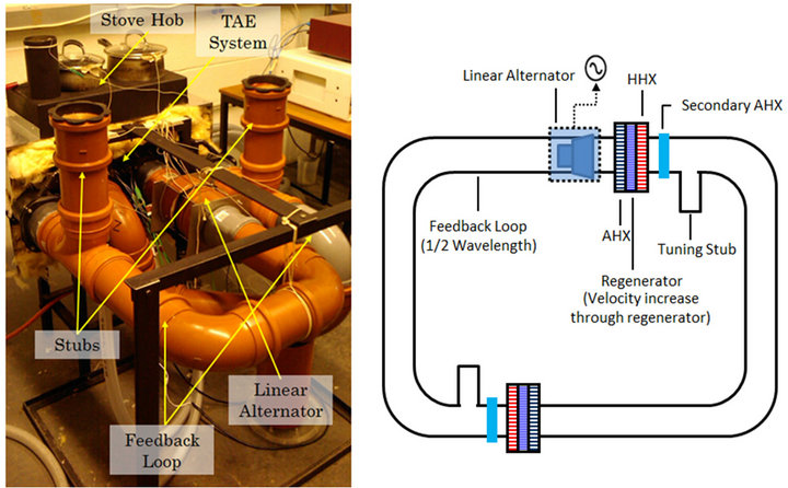
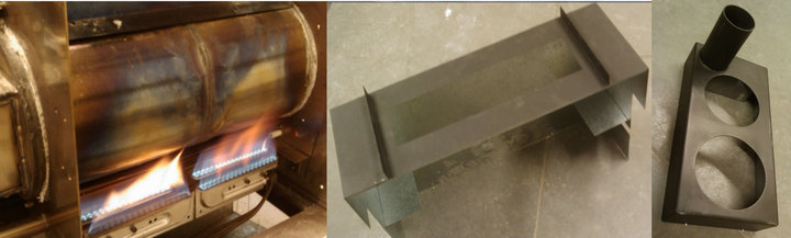
The general arrangement of the current propane-driven thermoacoustic generator consists of three main modules: Thermoacoustic Engine System (TAE system), Stove Carcase and Linear Alternator. The TAE system is composed of two regenerator units and Feedback Loops, where each regenerator unit comprises Hot Heat Exchanger, Ambient Heat Exchanger and Regenerator [6]. Two equal-length loops are the Feedback Loops that connect these two regenerator units together and are configured in what we call Push Pull configuration. The stove carcase as depicted in the Figure 1 consists of Combustor (burners), Engine Housing and Cooking Hob. An additional pipe is connected perpendicularly to each loop denoted as Stub for impedance tuning. A linear alternator is coupled in one of the loop near to the ambient heat exchanger to extract the electrical power from the acoustic loop [7]. Figure 1 shows three LED units were powered by a propane-driven generator using a loudspeaker as an electricity generator.
Working Principle: A commercial propane gas cylinder was used to supply the propane to the burners assembly using gas flow controller. The flames inside the combustion chamber first heat up the radiant bulge rapidly to temperatures above 850˚C (bright orange) in minutes. The radiant bulge then transfers most of the heat to one side of the regenerator mesh mainly by radiation, this is the heat input to the TAE system. Heat on the other side of the regenerator is rejected by the ambient heat exchanger. Water circulation brings the heat (rejected heat) out from the radiator and sustains the radiator at the temperature of about 35˚C. The rejected heat of the TAE system can be used for cooking and/or water purification for drinking. As depicted in Figure 1, the feedback loop was connected in pull push configuration to form a closed loop thermoacoustic travelling wave system. The stub was used to tune the impedance matching between acoustic loop and linear alternator. A liner alternator then extracts electrical power from the acoustic loop and powers the LED lights as illustrated in Figure 1. To achieve adequate electricity output, a higher acoustic intensity is required and so the working pressure can be increased up to 200 kPa(gauge) [8]. Moreover, using Helium gas as working fluid can significantly improve the acoustic intensity. In a typical integration, about 50% of the combustion heat flows up to the heat-channel to the stove hob for cooking. Finally, system emission was taken out through a chimney.
Tae System: The TAE system is the core module that determines the overall performance of the entire system. As described, it is mainly composed of two identical cores and feedback loop, where each core comprises a hot heat exchanger, an ambient heat exchanger and a regenerator. This TAE system was developed to be integra-
 (a) (b)
Figure 1. General arrangement of the current propanedriven thermoacoustic generator.
ted with a propane-fired stove. This stove generates about 4 kW of thermal power where about half this power is used for cooking and half for powering the thermoacoustic engine. Unlike the traditional thermoacoustic engines (using internal electrical heating elements for heating) [4,8,9], the TAE system in this case is powered by waste heat from a cooking stove where the heat is provided to the TAE system externally. One of the design challenges is to ensure sufficient heat or the highest possible amount of wasted energy/heat (besides cooking) can be supplied to the TAE system so that the hot heat exchange could be heated up to the highest possible temperatures. In addition to that, avoiding or minimising system streaming due to convective heat is taken into the design consideration. Lastly, keeping the cost down is one of the project targets as well as one of the biggest constraints of the design. Consequently, a radiant bulge hot heat exchanger (HHX) design that can effectively transfers heat to the regenerator mainly by radiation and without disturbing the gas flow was proposed.
This HHX was made of 3 mm thick 304 heat resistant stainless steel bended to a 180 mm diameter semi-circular bulge with two semi-cylinders welded on both sides as depicted in Figure 2 (left). A semi-circular plate was welded in the middle of the bulge to separate it into two parts, where each part has a rectangular cross-section of 220 × 180 mm. This RHHX was then bolted to the ambient heat exchanger. The ambient heat exchanger was a modified radiator made from commercial, low-cost car radiator which is cooled by coolingwater circulation. It has two 35 mm diameter water inlet nozzles, one at the lower end and the other at the upper end of the radiator as depicted in Figure 2 (right). In operation, the water supply must be connected to the lower nozzle to avoid air locks occur in the radiator channels causing temperature soar and melting the radiators. From the front side of the radiator, two 120 mm-diameter holes were drilled for PVC adaptors, while on the other side, two rectangular holes with dimension of 180 × 155 mm were cut for the regenerator as illustrated in Figure 2 (right). Two additional tubes were welded to both sides of the radiator flanges denoted as thermal buffer tube as depicted in Figure 3 (left). The tubes were manufactured using a mild steel pipe with then end machined to mate with the comercially available drain fittings. It separates the feedback loop (PVC pipes) from the hot side of the TAE system. To protect the gasket lip seal of the PVC joints, the ambient end of the thermal buffer tube was filled with aluminium foam also known as secondary ambient heat exchanger. It was machined to fit inside the thermal buffer tube. Besides that, a cooling water jacket from main cooling loop was surrounding the tube at this section as depicted in Figure 3 (right).
The regenerator matrix is an important component of a thermoacoustic engine as discussed in the literature review. It composed of 45 layers of stainless steel wire mesh machined to a square size of 180 mm by 155 mm, and is placed inside each rectangular hole of the radiator as depicted in Figure 2 (right). A machined wire metal mesh is bolted to compact the regenerator mesh by four machined beams as depicted in Figure 4. The first few layers of the regenerator are heated by heat radiation from the inner wall of HHX. The specification of the regenerator is summarised in Table 1.
These two cores were then mounted with the RHHX and connected using the feedback loop. High power rate of thermoacoustic devices usually use thick metal tube with high pressure gas filled up to 30 bars [8,4]. The

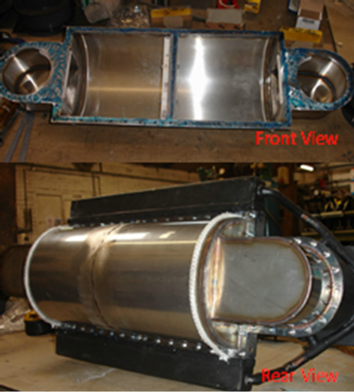
Figure 2. Radiant bulge hot heat exchanger (left); Ambient heat exchanger (right).
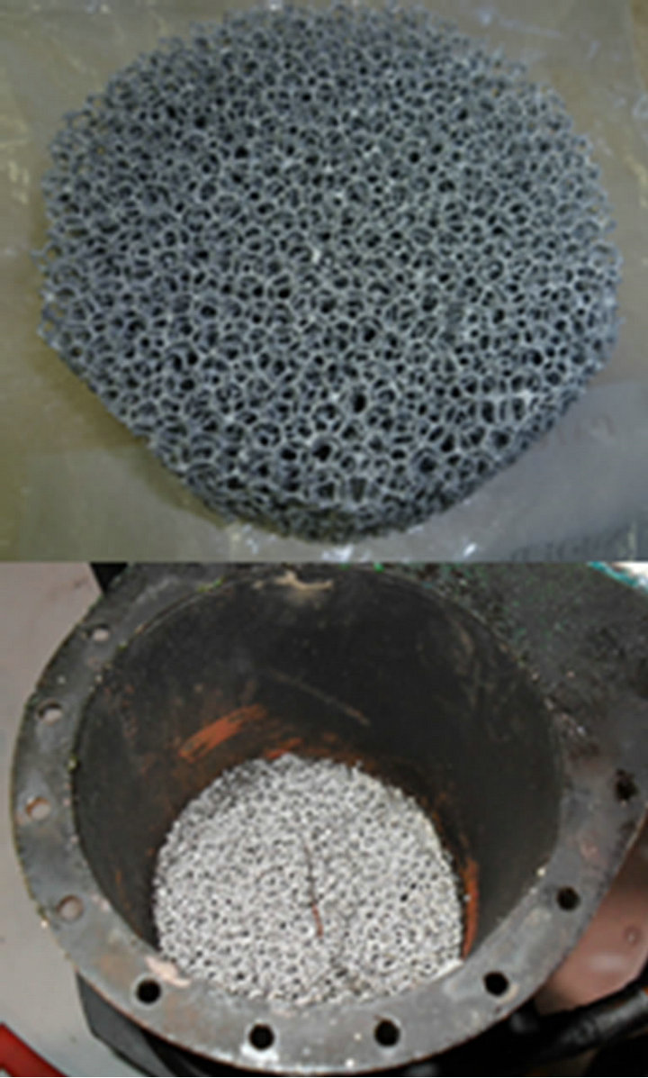
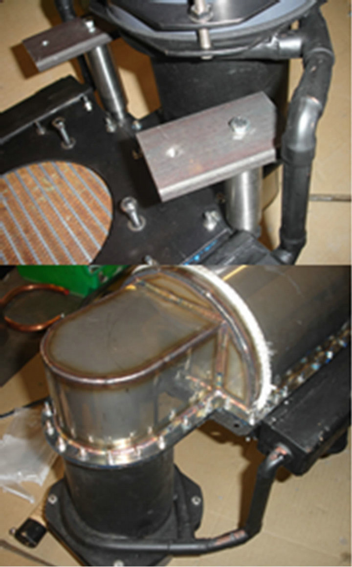
Figure 3. Thermal buffer tube (left); Secondary ambient heat exchanger (right).
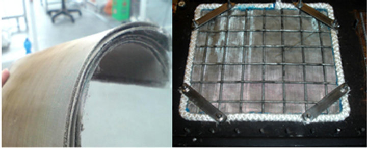
Figure 4. Regenerator (Stainless steel mesh).
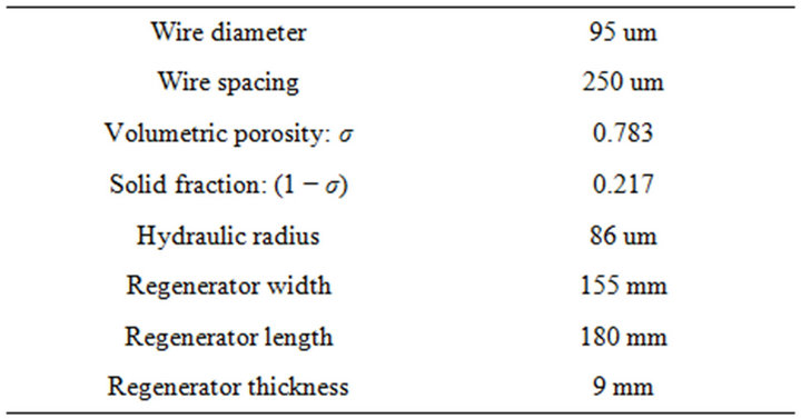
Table 1. Specification of the regenerator.
propane-driven thermoacoustic generator was design to operate with air/Helium at atmospheric pressure, however the system can be pressurised up to 200 kPa(gauge). In order to reduce assembly costs and allow higher flexibility for configuration investigation, the feedback loop was constructed from standard underground PVC pipes with appropriate fittings. The standard PVC pipe (Marley) is a high quality solid-wall pipe with 100 mm (4-inch) inner diameter. Its corresponding high quality solid-wall fittings are also available with built-in ring seal, double socket couplings and bends of difference curvature. This allows the maximum flexibility as the entire prototype can be reconfigured to operate independently or with the two halves interconnected feedback loop in series or push pull configuration. Furthermore, an additional pipe (a blind brand) called the tuning stub was connected perpendicular to each part of the feedback loop close to the thermal buffer tube using a “T” branch to improve the impedance matching between acoustic loop and linear alternator. This stub has the same diameter as in the main loop and the length of it on both sides has been observed in a range from 100 mm to 500 mm. The end of the stub was closed by a commercially available PVC cover.
Linear Alternator: A flexure-bearing-supported linear alternator is a good solution due to its high efficiency and reliability [3], but it has a relatively high cost which limits the advantage of the thermoacoustic engines as a lowcost energy converting device. Therefore, a test alternator is built using a commercially available, low-cost loudspeaker (B&C 6PS38) with a cone diameter of 130 mm operated in reverse to act as an electro-acoustic alternator. Its specification and the Thiele & Small parameters are summarised in Table 2.
Enclosure housing must be fitted around the loudspeaker to be interfaced to the thermoacoustic converter. The loudspeaker’s flange was machined to suit well into a standard coupling reducer (6 to 4-inch). Another coupling reducer was coupled on the other side of the loudspeaker as depicted in Figure 5 and it can now fittings readily compatible with the feedback loops.
Stove Carcase: The stove carcase consists of three units as illustrated in Figure 6, namely the burners, en-
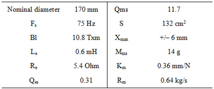
Table 2. Specification and Thiele & Small parameters of the loudspeaker.
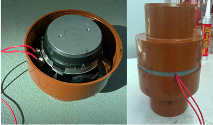
Figure 5. The enclosure housing linear alternator.
gine housing and cooking hob. Four commercial propane burner assemblies (Plastimo Atlantic Oven burners) with two gas flow controllers were installed below the HHX. Each burner is rated 1.5 kW, for a total of 6 kW maximum nominal powers. The burners’ flames were directed towards the HHX. The engine housing was made of thin mild steel tightly fixed with the TAE system and providing a support for the cooking hob. The cooking hob was made of mild steel with two different diameters’ holes, one is 170 mm and the one is 185 mm. A 90 mm hollow cylinder with length of 155 mm was welded on the top right corner of the cooking hob serving as a chimney. In order to achieve better combustion efficiency, a mass of heat resistant, low thermal conductivity wool insulation (Rockwool) was applied between the combustion chamber and the engine housing as well as the inner wall of the cooking hob to minimise heat losses. Moreover, the design of the stove such as air-fuel rate controlling and effective gas-path study is taken into consideration, however it is out of this study scope and the detailed study of a high efficiency stove can be found elsewhere.
4. Design of the Wood-Burning Generator
The design efforts are targeted at achieving functionality based on low onset temperature concept and then minimising its fabrication cost by using commercially available standard parts. Therefore, elements of the TRIZ methodology is employed to maximise the functionality of each component while minimising its cost. The main design strategy was discussed elsewhere [10-13].
The general design outline of the wood-burning thermoacoustic generator is illustrated in Figure 7. It consists of four main modules: Stove Carcase (including combustion chamber and insulation), Stove Hob, TAE System, Linear Alternator and Water Reservoir (not shown in figure). Obviously, the TAE system is the main module that determines the overall performance and is the most costly module of the entire system. This TAE system combines two identical thermoacoustic engines and the feedback loops. These two engines also known as the Demo2 TAE positioned close to each other in a dual-regenerator configuration. Typically, a single-stage Demo2 TAE consists of five modules: Corrugated HHX, Regenerator, Ambient Heat Exchanger, and Thermal Buffer Tube [14]. Two different loops of length are the Feedback Loops that connected these two engines together and are formed a quarter wavelength configuration. Generally a linear alternator is connected in series to one of the feedback loop and positioned close to one of the ambient heat exchanger [7]. The current Demo2 design TAE has evolved through five stages to approach the functional requirements as well as the cost targets.
Working Principle: Heat is supplied to the TAE system by burning of fuel (not shown in figure) inside the combustion chamber of the stove. Both convoluted hot heat exchangers (convoluted HHXs) then heat up rapidly to a temperature of around 700˚C and transfer heat to one
 (a) (b) (c)
Figure 6. Stove unit. (a) The burners; (b) The engine housing; (c) The cooking hob.
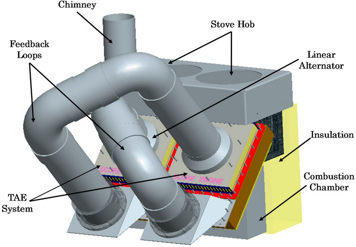
Figure 7. General design outline of the wood-burning thermoacoustic generator.
side of each regenerator by a combination of conduction and radiation. Heat on the other side of each regenerator is rejected to the ambient heat exchangers. A water reservoir (not shown in figure) is made out of a standard 55 gallon drum cut in half and positioned toward the ambient heat exchangers to take heat from the thermoacoustic engines using the auto siphon effect for water circulation, therefore eliminating the need for a pump. The rejected heat of the TAE system can be used for cooking and/or water purification for drinking. As depicted in Figure 7, the feedback loops are connecting both thermoacoustic engines in series to form a closed loop system. The lengths of the feedback loops are configured to approach a quarter wavelength and three quarter wavelength travelling wave condition. This because the quarter wavelength devices are able to reduce reflections (in the same way that quarter wavelength coatings are put in spectacles to reduce unwanted reflections at optical frequencies) and three quarter wavelength have the same property. Thus, the effects of impedance mismatches are reduced that produces a near travelling wave around the loop, hence minimising losses. Moreover, to achieve adequate electrical output, early tests have shown that a higher acoustic intensity is required and so the working pressure is increased up to 200 kPa(gauge) [8]. Beyond the TAE system, about half amount of the remaining combustion gas then flows up through a heat-guide to the stove hob for cooking. Finally, system emission is taken out through a chimney.
5. Experimental Results and Discussion
This experiment was conducted at atmospheric pressure and ambient room temperature. The working fluid used for the TAE system was air. The general experimental setup of the experiment is illustrated schematically in Figure 8. A propane gas cylinder supplies burning gas to the system. The ambient heat exchange is running on tap water (a total loss cooling system) and rejected water is collected using a water tank. A water flow meter (KDG Mobrey) and gas flow meter (Uniflux SSB-9) is adopted for monitoring the water and gas flow rate of the system. The readings of these thermocouples (Type-KRS Components) as well as the pressure transducers (model HKM- 233-375) are obtained using a Data Acquisition (NI cDAQ 9172) with three thermocouple modules (NI 9211) and one bridge module (NI 9237). This data acquisition then is connected to a data logger system (workspaces with appropriate software developed by Score). Our preliminary measurement shows that the temperature distribution on the engine housing’s surface was nonuniform, in order to obtain better accuracy of measurement results, the entire engine housing as well as the stove hob is divided into many small sections (around 100 mm × 5 mm for a section) and each section’s temperature is obtained
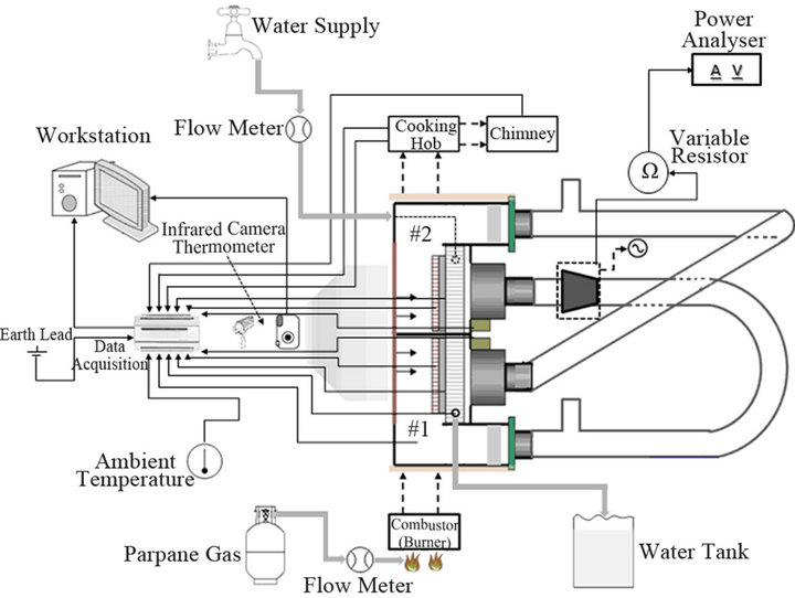
Figure 8. Schematic diagram of the experimental setup for propane-driven generator.
using an Infrared Thermometer (Testo 830). In additional, a FLIR Systems Infrared Camera is used to capture infrared images that show the overall temperature distribution of the engine housing and the cooking hob. For electrical power measurement, a wide range (100 Ohm 100 W) variable resistor (VISHAY®) is adopted as an electrical load for the alternator to extract electrical power. The voltage and the current are measured using a Power Analyser (KinetiQ PPS2530).
Figure 9 depicts the readings of the thermocouples over the entire experiment period (about 1 hour). Initial oscillation at frequency of 150 Hz was found after about 20 minutes of running. The onset temperature difference is observed to be approximate 385˚C (Thot ≈ 398˚C) while the corresponding pressure amplitude at one of the ambient heat exchanger was 32 Pa. As the temperatures keep rising up, a strong oscillation was occurred when the RHHX’s temperature reach about 450˚C after about 43 minutes of running. The frequency now was found to be 72 Hz, and the maximum pressure amplitude was 8412 Pa. The RHHX’s temperature then immediately drops to about 200˚C and the system reaches steady state after about 43 minutes of running as depicted in Figure 9. This can be understood that the amount of these heats (temperatures drop) is converted to acoustic energy (wave oscillation). The steady state pressure of the TAE system maintains at about 3600 Pa. The linear alternator produces a maximum of about 15 We with 10 Ω resistance. The temperature difference of 3.7˚C was obtained on the water inlet and outlet nozzles. An amount of 1 litre of water in each pan was boiled after running of approximately 25 minutes.
The flow of power through the system was obtained and a summary of the results is illustrated in Figure 10. A total of 4.66 kW of heat from burners assembly is supplied to the system. It is estimated that about half the amount of the heat is consumed by the cooking process which is only 1.17 kW of heat is utilised for cooking where the rest is lost to the engine housing and chimney by radiation and natural convection respectively. Around half amount of the remaining heat is supplied to the TAE system however about half of this amount of heat is rejected by the cooling water. The thermal buffer tube radiates approximately 270 watts of heat to the ambient. Therefore, it is estimated that only 460 watts of heat can be converted into acoustic power. Due to the power conversion and transmission loss on power delivery and linear alternator (mechanical and electrical loss), the linear alternator finally extracts 15 watts of electrical power.
A more detailed power and losses from the system and efficiency of each stage are summarised in Table 3. About 25.13% of the total amount of the power was utilised for cooking, which is acceptable in the current stage, however it can be still improved by reducing heat loss on the engine housing and the described gas transition. About 10% of the power is going to the TAE system, from which 18.15% can be converted to acoustic power. The loudspeaker produces a maximum of 15 watts of electricity at the available heat input of 460 watts to TAE system is relatively low compared to the simulation predictions (for
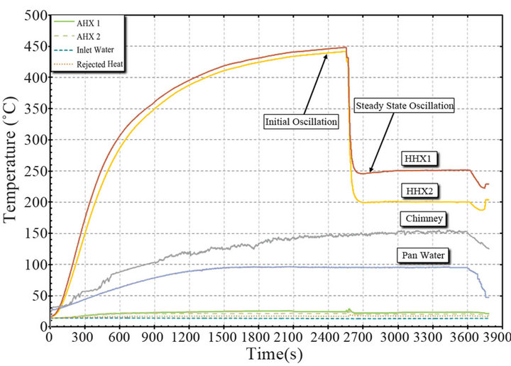
Figure 9. Temperature vs time over the testing period.
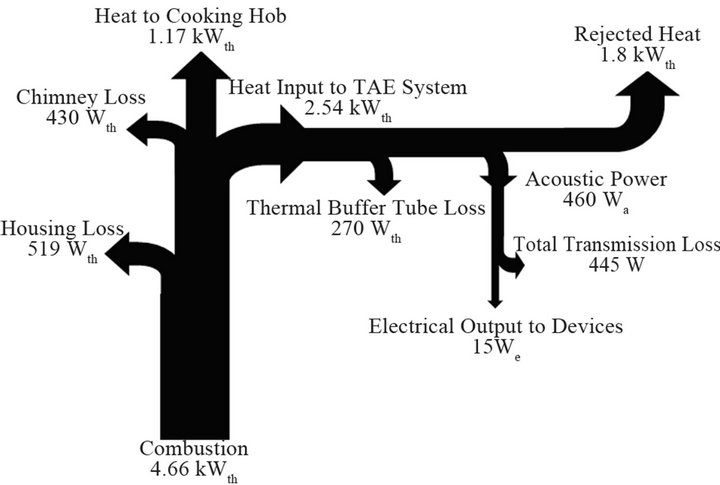
Figure 10. Summary power flow of the system.
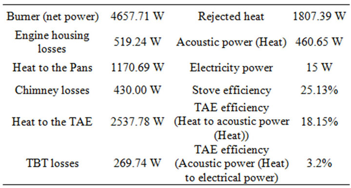
Table 3. General power summary of the system.
example, 15 watts of electricity output over 460 watts of heat input gives a figure of only 3.3%). However, it is possible to consider the amount of heat consumed by the TAE system is a waste energy from the cooking process, therefore the actual efficiency figures may be considered as a secondary matter, as long as the electrical power could be extracted at a very low cost per kWhr.
During the design phases, a simplified Demo2 TAE based on the stage 3 design was built by Aster Thermoakoestische Systemen of the Netherland and successfully demonstrated by integrating with a wood-burning stove at the City University of London. This demonstration was made to verify the concept of the new planar Demo2 design as well as to understand the interaction between the Demo2 TAE and wood combustion.
The general arrangement of the testing is illustrated in Figure 11. The TAE system is positioned at the angle of 45 degree on the stove housing which was made of low cost fire-brick. As mentioned previously, the stated orientation of the TAE system allows the burning gases of the wood to flow along and between the convolutions. Based on the concept of the planar design, this TAE system consists of two identical thermoacoustic engines close to each other. These two engines are then connected by the feedback loops, where are made out of low-cost PVC pipes and fittings. The inner diameter of the pipe is 75 mm this is smaller than required in the design. (100 mm diameter PVC pipe in the Demo2 TAE design) The length of each loop was configured to approach a quarter wavelength travelling loop. The hot heat exchanger is a convoluted HHX simulated back to back aluminium heat sinks (as an easier way to prove the planer concept before full convolution tooling was made).
The regenerator matrix composes of 65 layers of stainless steel wire mesh machined to a square size of 200 mm by 200 mm, and is compressed between the radiator and the aluminium heat sinks. The thickness of the regenerator is 15 mm.
A loudspeaker as described previously was used as a linear alternator and was coupled near to the ambient heat exchanger to extract the electrical power from the circulating acoustic power.
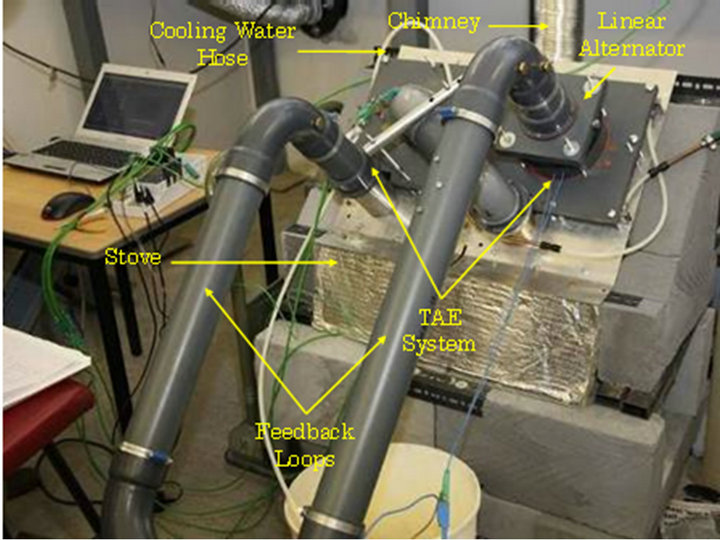
Figure 11. General testing outline of the simplified Demo2.
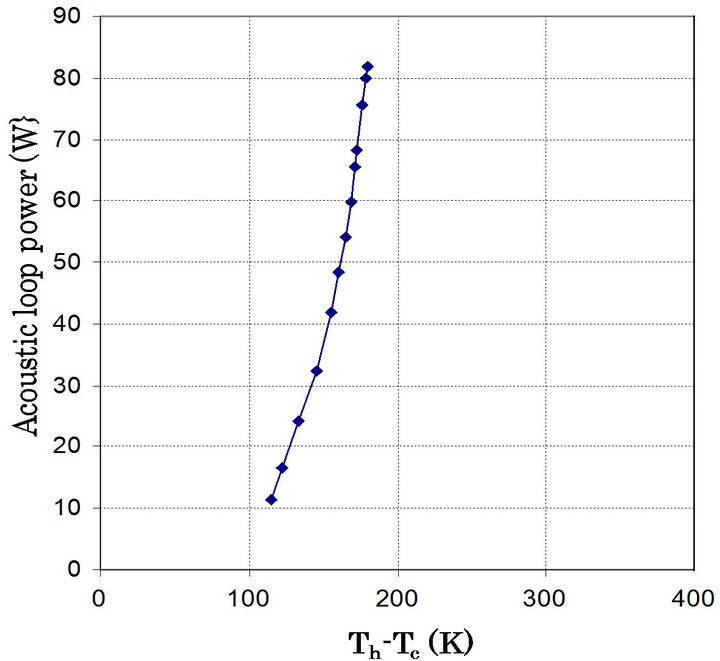
This experiment was initially conducted at atmospheric pressure and ambient room temperature. A pressurised system was also investigated in this experiment. The working fluid used for the TAE system was air. A total of about 1.5 kg wood with around 20% moisture content which is equivalent to 7 kW thermal heats was consumed over the first hour. The stove produced an average flame temperature of about 750˚C and a maximum of about 1000˚C. It was found the TAE system was oscillating at a frequency of about 80 Hz in 15 minutes after ignition. The performance of the thermoacoustic engine is indicated by the onset temperature difference and steepness of the loop power versus temperature curve. A low onset temperature indicates low loss and good acoustic matching of the various components. A steep curve indicates low acoustic loss and adequate heat transfer of both the cold and hot heat exchangers. Figure 12(a) shows an onset temperature difference of about 100˚C at the unloadded condition (no loudspeaker attached). This is quite low (less than 30% compared to the propane-driven generator) for an atmospheric device and it indicates the system was in optimal matching condition. The drive ratio was found to be 3.4% at 57 watts loop power where the corresponding pressure amplitude at one of the ambient heat exchangers was approximately 3400 Pa. For the engine was loaded with a loudspeaker, the measured acoustic to electric efficiency was found to be 28%. It was found that the onset temperature difference is about 60˚C higher than for the unloaded engine due to acoustic dissipation, radiation losses to the open air also slightly reducing the curve steepness. At the maximum measured loop power of 80 watts acoustic power the pressure amplitude at the ambient heat exchanger was 4600 Pa.
The maximum electrical power at atmospheric pressure condition was measured to be 12.6 We with 24 Ω load resistances. Significant increase of power was found when the system was pressurised to 50 kPa gauge, a maximum of about 22.7 We with 12 Ω load resistances was obtained. The results are summarised and shown in in Table 4.
 (a)
(a)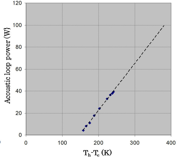 (b)
(b)
Figure 12. Measured acoustic loop power over onset temperature curve of the engine. (a) Unloaded condition; (b) Loaded condition.
6. Conclusions
This article reviews on propane-driven and wood-burning thermoacoustic generators which both are operating by waste heat from cooking stove. These two generators have been successfully demonstrated to produce an acceptable amount of electricity for the use of rural communities. A comprehensive power assessment of the propane-driving generator as well as the development and performance assessment of the wood-burning generator were discussed.
The power flow in the system of the propane-driven generator was illustrated in a power flow diagram. A stove efficiency of 25.13% was found to be acceptable in this stage. The acoustic-electric conversion efficiency was found to be low due to the low net acoustic power and inefficient alternator. However, this low amount of electricity generated could be acceptable since the system has a very low cost per kWhr. In general, the system overall efficiency need to be improved.
The wood-burning thermoacoustic engine was tested and found to generate about 57 W of circulating acoustic loop power at low flame temperature of wood at an unloaded condition, and it successfully produced a maximum of 22.7 watts of electricity using a comercially available loudspeaker as alternator.
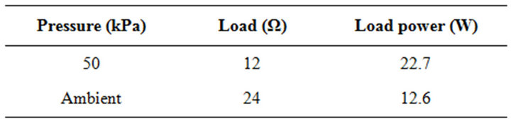
Table 4. Measured electrical load power from the loudspeaker.
7. Acknowledgements
The support of EPSRC for this work under the “Score” project and MOSTI is gratefully acknowledged, as are the contributions of the other partners in the project, especially thanks also to Kees deBlok of Aster Thermoakoestische Systemen.
REFERENCES
- K. De Blok, “Low Operating Temperature Integral Thermo Acoustic Devices for Solar Cooling and Waste Heat Recovery,” Journal of the Acoustical Society of America, Vol. 123, No. 5, 2008, pp. 3541-3541. doi:10.1121/1.2934526
- B. M. Chen, P. H. Riley, Y. A. Abakr, K.Pullen, D. B. Hann and C. M. Johnson, “Design and Development of a Low-Cost, Electricity-Generating Cooking Score-Stove™,” IET Renewable Power Generation, 2011.
- C. R. Saha, P. H. Riley, C. M. Johnson, J. Paul, Z. Yu and A. J. Jaworski, “Halbach Array Linear Alternator for Thermo-Acoustic Engine,” Energy Conversion and Management Journal, Vol. 178, 2012, pp. 179-187.
- S. Backhaus and G. Swift, “A Thermoacoustic-Stirling Heat Engine: Detailed Study,” The Journal of the Acoustical Society of America, Vol. 107, No. 6, 2000, pp. 3148- 3166. doi:10.1121/1.429343
- G. W. Swift, “Thermoacoustic Engines,” The Journal of the Acoustical Society of America, Vol. 84, No. 4, 1988, pp. 1145-1180. doi:10.1121/1.396617
- G. W. Swift and S. L. Garrett, “Thermoacoustics: A Unifying Perspective for Some Engines and Refrigerators,” The Journal of the Acoustical Society of America, Vol. 113, No. 5, 2003, pp. 2379-2381. doi:10.1121/1.1561492
- Z. Yu, A. J. Jaworski and S. Backhaus, “Design of a Low-Cost Thermoacoustic Electricity Generator and Its Experimental Verification,” ASME 10th Biennial Conference on Engineering Systems Design and Analysis, Vol. 1, 2010, pp. 191-199.
- E. C. Luo, Z. H. Wu, W. Dai, S. F. Li and Y. Zhou, “A 100 W-Class Traveling-Wave Thermoacoustic Electricity Generator,” Chinese Science Bulletin, Vol. 53, No. 9, 2008, pp. 1453-1456. doi:10.1007/s11434-008-0200-1
- G. Yu, E. Luo, W. Dai and Z. Wu, “An Energy-Focused Thermoacoustic-Stirling Heat Engine Reaching a High Pressure Ratio above 1.40,” Cryogenics, Vol. 47, No. 2, 2007, pp. 132-134. doi:10.1016/j.cryogenics.2006.12.001
- Z. Yu and A. J. Jaworski, “Impact of Acoustic Impedance and Flow Resistance on the Power Output Capacity of the Regenerators in Travelling-Wave Thermoacoustic Engines,” Energy Conversion and Management, Vol. 51, No. 2, 2010, pp. 350-359. doi:10.1016/j.enconman.2009.09.032
- C. L. C. Gardner, “Design of a Standing-Wave Thermoacoustic Engine,” The Sixteenth International Congress on Sound and Vibration, Krakow, 5-9 July 2009.
- S. B. Z. Yu and A. J. Jaworski, “Design and Testing of a Travelling-Wave Looped-Tube Engine for Low-Cost Electricity Generators in Remote and Rural Areas,” 7th International Energy Conversion Engineering Conference, Denver, 2-5 August 2009.
- Y. Z. Abduljalil and A. J. Jaworski, “Experimental Characterisation of Low-Cost Regenerators for TravellingWave Thermoacoustic Devices,” Proceedings of 7th Annual International Energy Conversion Engineering Conference, Denver, 2-5 August 2009.
- C. R. Saha, P. H. Riley, C. M. Johnson and J. Paul, “Application of Thermo-Acoustic, Electrical Generating Engines in Rural Areas,” IIT Delhi, Delhi, 7-9 September 2010.