Engineering
Vol. 4 No. 2 (2012) , Article ID: 17435 , 7 pages DOI:10.4236/eng.2012.42016
Enhancement of Ride Quality of Quarter Vehicle Model by Using Mixed H2/H∞ with Pole-Placement
1Automotive and Tractors Engineering Department, Faculty of Engineering, Helwan University, Cairo, Egypt
2Electrical Power and Machine Department, Faculty of Engineering, Helwan University, Cairo, Egypt
Email: Ashraf_galab@yahoo.com, ghanymohamed@ieee.org
Received November 26, 2011; revised January 4, 2012; accepted January 10, 2012
Keywords: Mixed H2/H∞; Semi Active Suspension; Pole-Placement; Ride Quality; Linear Matrix Inequality (LMI)
ABSTRACT
The aim of the present work is to illustrate the application of mixed H2/H∞ control theory with Pole-Placement in designing controller for semi-active suspension system. It is well known that the ride comfort is improved by reducing vehicle body acceleration generated by road disturbance. In order to study this phenomenon, Two Degrees of Freedom (DOF) in state space vehicle model was built in. However, the role of H∞ is to minimize the disturbance effect on the output while H2 is used to improve the input of controller. Linear Matrix Inequality (LMI) technique is used to calculate the dynamic controller parameters. The simulation results show that the H2 and H∞ techniques can effectively control the vibration of vehicle system where the reduction of suspension working space, dynamic tire load and body acceleration. Moreover, the simulation results show that the (RMS) of suspension working space was reduced by 44.5%, body acceleration and dynamic tire load are reduced by 18.5% and 20% respectively.
1. Introduction
The purpose of using car suspension system is to provide rider comfort, ensure contact with the road impel terrain and of course to carry the weight of the chassis and the riders. Conventional suspension systems normally used on vehicles consist of springs and dampers with fixed dynamic characteristics, i.e. passive in nature. Over the years there has been a great increase in the operational velocity of passenger cars and a demand for better ride comfort. This has led to the development of active suspension systems with an additional actuator or a variable damper element along with the traditional spring and damper system The use of active suspension on road vehicles has been considered for many years [1-5]. A large number of different arrangements from semi-active to fully active schemes have been investigated [6-9]. There has also been interest in characterizing the degrees of freedom and constraints involved in active suspension design.
Many active suspension control approaches have been proposed such as Linear Quadratic Gaussian (LQG) control, adaptive control, and non-linear control to overcome these suspension systems problems [10-12].
Robust control alleviates such handicap with the use of H∞ controller. The later can minimize the disturbance effect (disturbance rejection) whereas H2 helps improveing the transients of some system outputs. Fast decay, good damping and reasonable controller dynamics can be imposed in a proper region in the left complex half plane. Neither H2 nor H∞ algorithms can do any effect towards minimizing body acceleration and observing suspension displacement restriction at same time [13-16]. So, mixed H2/H∞ control algorithm which is an H2 problem with H∞ constrains seems to be a good choice and has been applied to the considered quarter car model of suspension system in this paper.
Stability represent the minimum requirement for control systems has been obtained. However, in most cases, a good controller should act sufficiently fast with welldamped response beside the disturbance attenuation on selected system outputs.
2. Model Used in the Semi-Active Suspension Design
The basic model of a semi-active suspension system that describes car suspension system behavior is a quarter-car model. It consists of a wheel, a spring/damper, a controllable linear power source and a quarter of the body mass. This model allows simulating tire pressure, body acceleration and vertical body displacement as shown in Figure 1.
Dynamic Model Equations
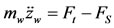
In this section, a quarter car-model with two degrees of freedom is considered. The model uses a unit to create the control force between body and wheel masses. The motion equations of the car body and the wheel are written as:
 (1)
(1)
 (2)
(2)
where: (FS and Ft) are suspension and tire forces respecttively, in N.
(FS and Ft) are represented by the following equations:
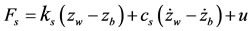 (3)
(3)
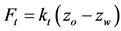 (4)
(4)
Assume the following 
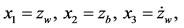 then
then ,
,  where mb and ms are the masses of vehicle body and wheel in kilograms zb and zw are the displacements of vehicle body and wheel, meters, ks and kt are the suspendsion and tire stiffness respectively in N/m, cs is the damper coefficient in N·s/m, and zo is the road input excitation, in meters.
By substituting Equations (1) and (2) in Equations (3) and (4) we get.
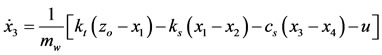 (5)
(5)
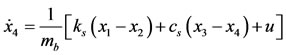 (6)
(6)
where; u is the control force from the hydraulic actuator.
By combining the equations and formulating them in a state space form, we get:
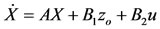
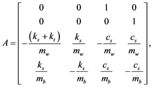
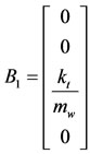 , and
, and 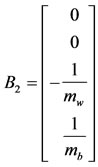
The quarter model parameters are listed in Table 1.
3. Road Excitation Model
A periodic road excitation input has been used for simulation of suspension systems. The periodic input is used for smooth road in order to evaluate ride comfort. It is widely recognized that the road surfaces approximate to Gaussian processes, having a power spectral density (PSD) of the form [17]:
 (7)
(7)
where:
Rc Road roughness coefficient.
f Road excitation frequency, Hz.
4. Robust Mixed H2/H( with Pole-Placement Controller
Noise attenuation or regulations against random disturbances are more naturally expressed in LQG or H2 terms. Besides, H¥-synthesis only enforces closed-loop stability and does not allow for direct placement of the closed-loop poles in more specific regions of the left-half plane. Since the pole location is related to the time response and transient behavior of the feedback system, it is often desirable
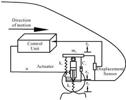
Figure 1. Semi-active suspension system.
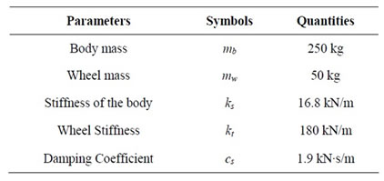
Table 1. Quarter car parameters.
to impose additional damping and clustering constraints on the closed-loop dynamics. This makes multi-objective synthesis highly desirable in practice, and LMI theory offers powerful tools to handle such problems.
Mixed H2/H¥-synthesis with regional pole placement is one example of multi-objective design addressed by the LMI. The control problem is sketched in Figure 2. The output channel z¥ is associated with the H¥ performance while the channel z2 is associated with the H2 performance (LQG aspects) [18-20].
4.1. System Representation
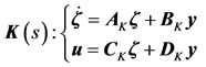
Figure 2 shows the standard representation of the robust output-feedback control block diagram where P(s) is the plant and K(s) represents the controller that is usually of the same order as the plant, let:
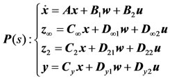 (8)
(8)
 (9)
(9)
and
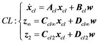 (10)
(10)
Be the corresponding closed-loop state-pace equations with.

Denoting by T¥(s) and T2(s) the closed-loop transfer functions from w to z¥ and z2, respectively, are:
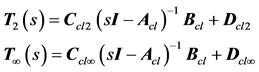 (11)
(11)
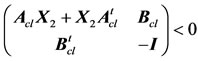
4.1.1. H( Performance
Lemma 1: The closed-loop random Mean Square (RMS) gain for T¥(s) does not exceed γ, if and only if there exists a symmetric matrix such that [16]:
 (12)
(12)
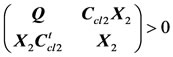
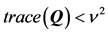
4.1.2. H2 Performance
Lemma 2: The closed-loop H2-norm of T2(s),
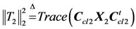 does not exceed
  if and only Dcl2 = 0 and there exist two symmetric matrices X2 > 0 and Q such that [16]:
 (13)
(13)
 (14)
(14)
 (15)
(15)
4.1.3. Pole-Placement Technique
The concept of LMI region [15,16,18,20] is useful to formulate pole-placement objectives in LMI terms. They are convex subsets D of the complex plane C characterized by:

where: M and  are fixed real matrices,

where: 
 = complex number.
More practically, LMI regions include relevant regions such as sectors, disks, conics, strips, etc, as well as any intersection of the above. Only a shift in the left-hand side plane, as shown in Figure 3, is considered. Its character-
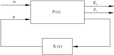
Figure 2. Output feedback block diagram.
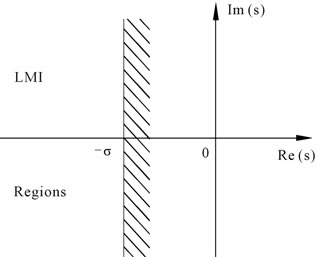
Figure 3. Pole-placement region.
istic function with , is
, is
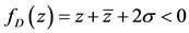 , Thus
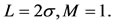
From a Theorem in [16,21], the pole-placement constraint is satisfied if and only if there exists Xp > 0 such that:
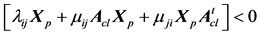 with
with  (16)
(16)
4.2. Multi-Objective Design
Design an output-feedback controller u = K(s)y through the minimization of a trade-off criterion of the form:
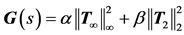 (17)
(17)
• Maintains the H¥-norm of T¥(s) (RMS gain) below some prescribed value γ > 0.
• Maintains the H2-norm of T2(s) (LQG cost) below some prescribed value ν > 0.
• Places the closed-loop poles in some prescribed LMI region D.
For tractability in the LMI framework, convexity can be enforced by seeking a common solution:
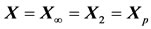 (18)
(18)
That can be obtained through the solution of Equations (11)-(13), (16), [16,20,21].
An efficient algorithm for solving this problem is available in function hinfmix of the LMI control toolbox in Matlab.
5. Simulation Results and Discussion
In order to evaluate the ride comfort and handling safety of active suspension system the dynamic deflection of the suspension system and the dynamic tire load should be considered except that the acceleration of sprung mass is considered as an important index.
5.1. System with RM H2/H(
The controller design technique is characterized by different types of Pole-placement relevant regions such as sectors, half-planes, disks, conics, strips.
Each type has useful facility to put the poles in different locations to obtain different dynamic performance. The multi-objective design has tuning variables represented by weighting coefficients α, β, γ and ν They affect the dynamic performance as shown in Figures 5-16.
5.2. Effect of α, β, γ and ν
A shift in the left-hand side s-plane (half-plane) is considered and different values of weighting coefficients α, β and prescribed values of γ > 0 and ν > 0 for H¥- and H2-norms are given in Table 2. Five cases were investigated with different values of parameters (α, β, γ, and ν). Figures 4-15 show the effect of parameters (α, β, γ and ν on the suspension performance, and Table 3 shows the root mean square for different parameters values. Table 4 shows the root mean square (RMS) values of system response for passive and controlled systems. From the table it is clear that the controlled system with H2/H¥ technique has a lower (RMS) value for the suspension working space, body acceleration, and dynamic tire load than the passive in improving the ride comfort. The mean root square of suspension working space reach to 44.5%, body acceleration 18.5%, and 20% for dynamic tire load.
6. Conclusions
In this paper, a semi-active suspension control with mixed H2/H∞ with pole-placement control technique, the handling safety and riding comfort of vehicle regarded as control aims, and mixed H2/H∞ technique is brought up.
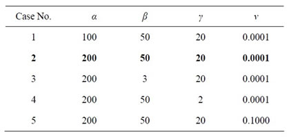
Table 2. Different values of the tuning variable of RM H2/H¥.
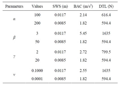
Table 3. The (RMS) of suspension system performance.
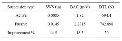
Table 4. The (RMS) of active and passive suspension system.
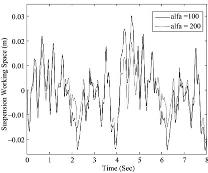
Figure 4. Suspension working space with different parameters of α.
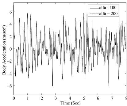
Figure 5. Body acceleration with different parameters of α.

Figure 6. Dynamic tire load with different parameters of α.
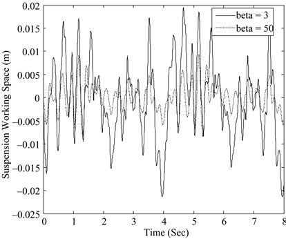
Figure 7. Suspension working space with different parameters of β.
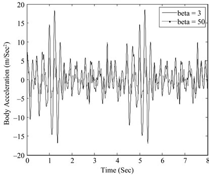
Figure 8. Body acceleration with different parameters of β.
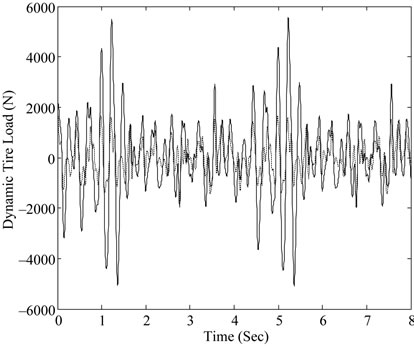
Figure 9. Dynamic tire load with different parameters of β.
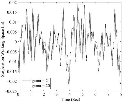
Figure 10. Suspension working space with different parameters of γ.
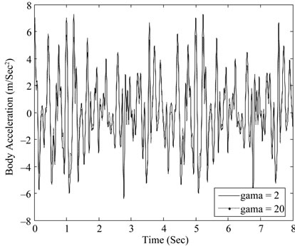
Figure 11. Body acceleration with different parameters of γ.
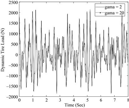
Figure 12. Dynamic tire load with different parameters of γ.
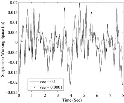
Figure 13. Suspension working space with different parameters of ν.
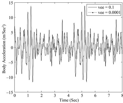
Figure 14. Body acceleration with different parameters of ν.
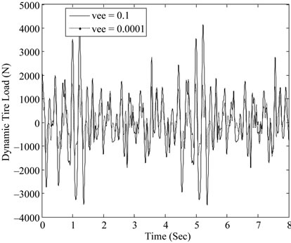
Figure 15. Dynamic tire load with different parameters of ν.
The vehicle can be influenced under the road excitation, so the mixed H2/H∞ with pole-placement control has adaptive ability. Control performance criteria such as suspension working space, body acceleration, and dynamic tire load are evaluated in time domain.
The controller design technique is characterized by different types of Pole-placement relevant regions such as sectors, half-planes, disks, conics, strips. Each type has useful facility to put the poles in different locations to obtain different dynamic performance.
The multi-objective design has tuning variables represented by weighting coefficients α, β, γ, and ν affect the dynamic performance.
A comparison of passive suspension against semi-active suspension for random road excitation through numerical simulation based on a quarter car model has been done. The simulated results reveal that the use of semiactive suspension with mixed H2/H∞ with pole-placement control technique has obvious effect on the suspension performance, and offers a considerable improvement on ride comfort.
REFERENCES
- A. G. Thompson, “Design of Active Suspensions,” Proceedings of the Institution of Mechanical Engineers, Vol. 185, No. 1, 1970, pp. 553-563. doi:10.1243/PIME_PROC_1970_185_060_02
- R. Pitcher, H. Hillel and C. H. Curtis, “Hydraulic Suspensions with Particular Reference to Public Service Vehicles,” Proceeding of Public Service Vehicles Conference, Mechanical Engineering Publications, London, 1977.
- D. Hrovat and M. Hubbard, “Optimal Vehicle Suspensions Minimizing rms Rattle Space, Sprung Mass Acceleration and Jerk,” Transactions of the ASME, Vol. 103, 1981, pp. 228-236.
- P. G. Wright and D. A. Williams, “The Application of Active Suspension to High Performance Road Vehicles,” Proceedings of IMecE Conference on Microprocessors in Fluid Power Engineering, Mechanical Engineering Publications, London, 1984, pp. 23-28.
- R. W. Newcomb, “Linear Multiport Synthesis,” McGrawHill, Boston, 1966.
- D. A. Crolla and A. M. A. Aboul Nour, “Theoretical Comparisons of Various Active Suspension Systems in Terms of Performance and Power Requirements,” Proceedings of IMecE Conference on Advanced Suspensions, Vol. 1-9, 24-25 October 1988.
- R. S. Sharp and S. A. Hassan, “On the Performance Capabilities of Active Automobile Suspension Systems of Limited Bandwidth,” Vehicle System Dynamics, Vol. 16, No. 4, 1987, pp. 213-225. doi:10.1080/00423118708968879
- P. G. Wright and D. A. Williams, “The Case for an Irreversible Active Suspension System,” SAE 1987 Transactions Journal of Passenger Cars, Vol. 6, 1989, pp. 83-90.
- R. A. Williams, A. Best and I. L. Crawford, “Refined Low Frequency Active Suspension,” International Conference on Vehicle Ride and Handling, Birmingham, November 1993, pp. 285-300.
- T. J. Gordon, C. Marsh and M. G. Milsted, “A Comparison of Adaptive LQG and Non-Linear Controllers for Vehicle Suspension Systems,” Vehicle System Dynamics: International Journal of Vehicle, Vol. 20, No. 6, 1991, pp. 321-340. doi:10.1080/00423119108968993
- A. Alleyne and J. K. Hedrick, “Non-Linear Adaptive Control of Active Suspensions,” IEEE Transactions on Control Control Systems Technology, Vol. 3, No. 1, 1995, pp. 94-101. doi:10.1109/87.370714
- M. B. Gaid, A. Cela and R. Kocik, “Distributed Control of a Car Suspension System,” COSI-EEIEE-Cite Descartes, Noisy-Le-Grand Cedex. http://www.esiee.fr/~kocikr/publis/Eurosim2004.pdf
- C. Scherer, P. Gahinet and M. Chilali, “Multi Objective Output Feedback Control via LMI Optimization,” IEEE Transactions on Automatic Control, Vol. 42, No. 7, 1997, pp. 896-911. doi:10.1109/9.599969
- V. T. Zanchin and A. S. Bazanella, ‘‘Robust Output Feedback Design with Application to Power Systems,” Proceeding of 42nd IEEE Conference on Decision and Control, Vol. 4, Maui, December 2003, pp. 3870-3875.
- P. S. Rao and I. Sen, ‘‘Robust Pole Placement Stabilizer Design Using Linear Matrix Inequalities,” IEEE Transactions on Power Systems, Vol. 15, No. 1, 2000, pp. 313-319. doi:10.1109/59.852138
- M. Chilali and P. Gahinet, “H∞ Design with Pole Placement Constraints: An LMI Approach,” IEEE Transactions on Automatic Control, Vol. 41, No. 3, 1996, pp. 358-367. doi:10.1109/9.486637
- A. Rowan, “Application of Electronically Controlled Suspension Systems to Military Vehicles,” MSc. Thesis, Helwan University, Cairo, 2004.
- P. Gahinet, A. Nemirovski, A. J. Laub and M. Chiali, “LMI Control Toolbox User’s Guide,” MATHWORKS Inc., Natick, 1995.
- A. Bensenouci and A. M. AbdelGhany, “Mixed H¥/H2 with Pole-Placement Design of Robust LMI-Based Output Feedback Controllers for Multi-Area Load Frequency Control,” The IEEE International Conference on Computer as a Tool, Warsaw, September 9-12 2007.
- Y. Nesterov and A. Nemirovskii, “Interior Point Polynomial Algorithms in Convex Programming: Theory and Applications,” SIAM Studies Studies in Applied Mathematics, Vol. 13, Philadelphia, 1994. doi:10.1137/1.9781611970791
- A. Nemirovskii and P. Gahinet, “The Projective Method for Solving Linear Matrix Inequalities,” Mathematical Programming Series B, Vol. 77, No. 2, 1997, pp. 163-190. doi:10.1016/S0025-5610(96)00085-8