Engineering
Vol. 4 No. 1 (2012) , Article ID: 17100 , 13 pages DOI:10.4236/eng.2012.41008
Performance Analysis of Automated Control System for Condenser Water Treatment Unit
Department of Mechanical Engineering, College of Engineering, Umm Al-Qura University, Makkah, Kingdom of Saudi Arabia
Email: asaalghamdi@uqu.edu.sa
Received October 19, 2011; revised November 20, 2011; accepted December 5, 2011
Keywords: Chilled Water Plants; Condensers; Cooling Towers; Water Treatment Chemicals; Automatic Chemical Treatment Controller; Performance Indicators
ABSTRACT
The air conditioning system in the Umm Al-Qura University (Albdiya Campus) was conceived to be a district cooling by a remote chilled water plant. Recently, there are two chilled water plants in the university installed strategically to provide chilled water to all the academic and administrative buildings of the university through distribution network with total capacity approximately of 12,000 tons of refrigeration. The plants were built based on cooling towers with open water cycle as heat rejection system. Water treatment chemicals has been used to protect the cooling systems from corrosion, scaling and microbiological fouling accompanied with dissolved and suspended water impurities. Different methods are being used to determine and control the treatment chemical concentrations and system performance indicators. Traditional chemical controller has drawback of indirect measurements and set points. The purpose of this paper is to present a solution to overcome the problems of traditional and conventional chemical treatment and control systems. Central cooling plant number (1) assigned to perform experimental setup using new chemical treatment technology. Advanced automatic chemical treatment controller installed on condensers (1, 2 and 3), and certain key performance indicators were selected and monitored such as chemical and water consumption, power, energy saving, and maintaining system integrity and efficiency. Satisfactory results were obtained in terms of performance and cost of operation.
1. Introduction
Cooling Water System
Cooling water systems are either open or closed, and water flow is either once-through or recirculation. The three basic types of cooling water systems are once-through, closed recirculation (non evaporative), and open recirculation (evaporative). True closed systems neither lose nor gain water during service. Open systems, however, must have water added to make up for losses.
Figure 1 shows the basic concept operation of once through cooling system; where the water passes though
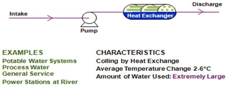
Figure 1. Once through cooling water system [1].
heat exchanger equipment only once. The runoff water temperature increases slightly due to using large volumes of cooling water. The mineral content of the cooling water remains practically unchanged as it passes through the system [1].
Figure 2 shows the basic concepts operation of closed recirculating water system, where the cooling water used continually in a cycle. First, the water absorbs heat from process fluids, and then releases it in another heat exchanger. In this system, an evaporative cooling tower is
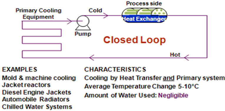
Figure 2. Closed recirculating water cooling system [1].
not included [1].
Figure 3 shows the operation principles of the open recirculating system. It is the most widely used industrial cooling design. It consists of pumps, heat exchangers, and cooling towers. The pumps keep the water recirculating through heat exchangers where it picks up heat and moves it to the cooling tower where heat is released from the water through evaporation. The water in open recirculating system undergoes changes in its basic chemistry [1,2].
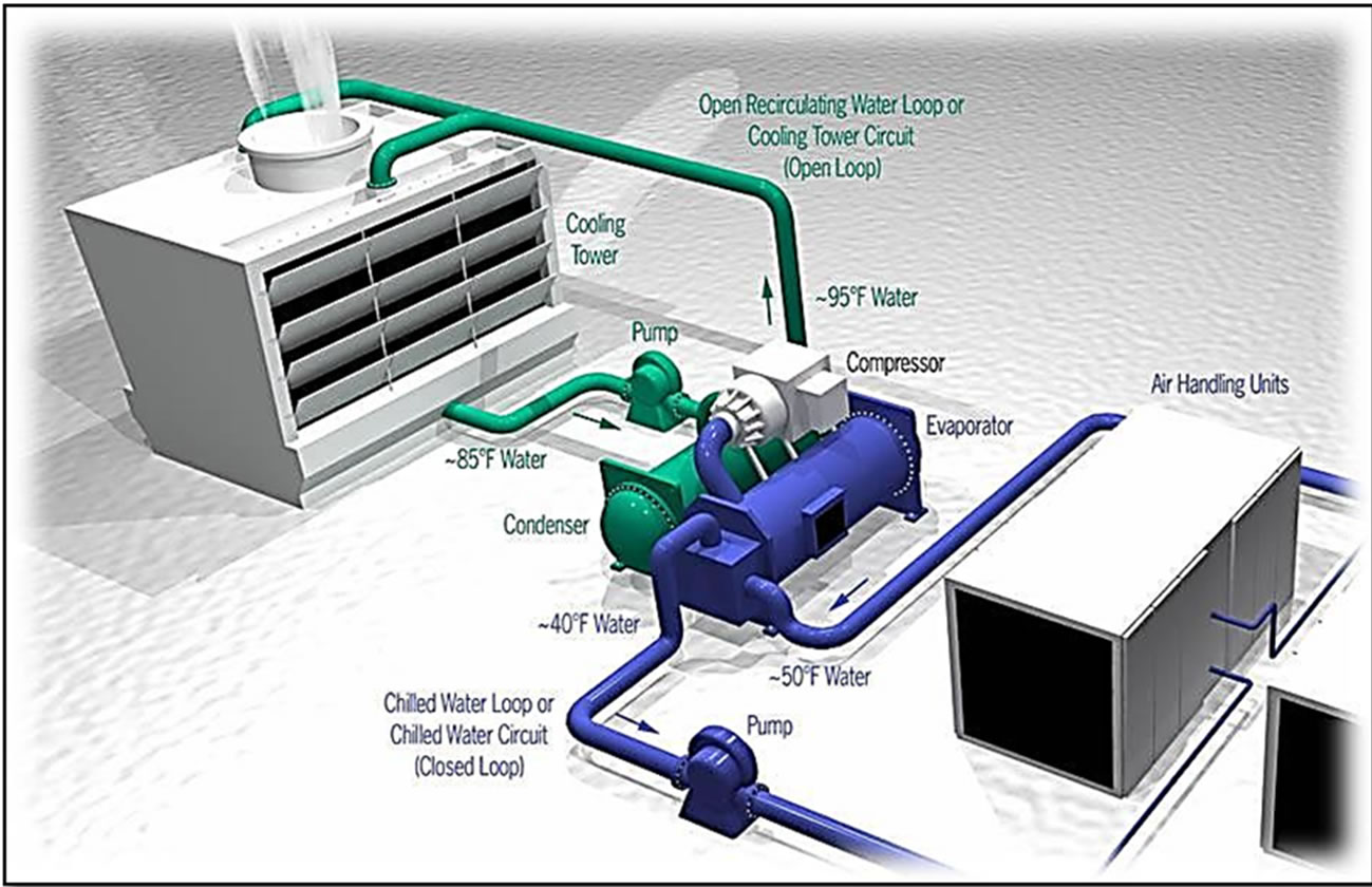
Both closed and open recirculating water coolingsystem are used in chilled water plants in the Umm Al-Qura University. The open recirculating water cooling system is used to provide chilled water to all the academic and administrative buildings of the university through distribution network with total capacity of 12,000 tons of refrigeration, and the closed recirculating water cooling system as heat rejection system. Figure 4 shows typical combination of both systems. Umm Al-Qura University owns and operates open recirculation cooling towers as shown Figure 5 to cool down the water-cooled type chillers by heat exchange with refrigerant through shell and tube exchanger with pump rate = 2350 m3/hr, volume = 550 m3, and DT = 6˚C.
2. Sources of Cooling Water
There are two main sources of cooling water fresh water and salt and wastewater. Fresh water is the primary source of makeup for cooling water systems. Fresh water can be surface water (rivers, streams, reservoirs) or ground water (shallow or deep well waters). In general, ground water supplies are more consistent in composition and contain less suspended matter than surface water supplies, which are directly affected by rainfall, erosion, and other environmental conditions. Because of environmental consideration, water cost and water availability, some plants are now using salt water and wastewater treatment plant effluents as source of cooling water. Closed attention to design and treatment of cooling system using these sources of water is critical for reliable performance and long life [2,5].
Recently, the chilled water plants in UQU use the city water and well water. However, there is a plane to use the wastewater treatment plant effluents as cooling water for the condensers in the plants. Therefore, it is essential to come up with new chemical treatment technology to overcome the problem of traditional and conventional chemical treatment and control systems.
3. Cooling Water Chemical Treatment
Practically speaking, no water is pure, whether naturally occurring or artificial. Most industrial water have a level of impurity usually measured in percentage, or parts per hundred. The water chemist seldom deals with water sources having percentage levels of impurity, except for seawater (about 3% dissolved mineral impurities), connate waters (produced with some crude oils, sometimes containing 20% to 30% dissolved salts), brackish waters, and certain industrial wastewaters [4].
3.1. Problems in Cooling Water Systems
Cooling systems suffer from many types of corrosion and failure. The diversity of attack is caused by differences in cooling water system design, temperature, flow, water chemistry, alloy composition, and operation.
1) Corrosion: Corrosion is defined as nature’s way of returning processed metals, such as steel, copper, and zinc, to their native states as chemical compounds or minerals [4]. In the presence of water and oxygen, nature relentlessly attacks steel, returning the elemental iron (Fe0) back to an oxide, usually some combination of Fe2O3 and Fe3O4.
2) Deposition: Deposits are defined as conglomerates that accumulate on water-wetted surfaces and interfere with system performance, either by gradually restricting flow or by interfering with heat transfer [4]. Deposits include scale, foulants, or a combination of the two. Scale forms when the concentration of a dissolved mineral exceeds its solubility limit and the mineral starts to precipitate. The most common example of deposition is calcium carbonate scale formed when the Langelier index or the stability index indicates a condition of CaCO3 super-saturation. A foulant is any substance present in
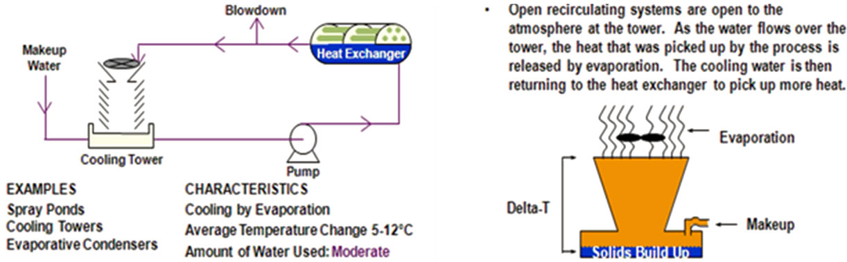
Figure 3. Open recirculating water cooling system [1].
 (a)
(a)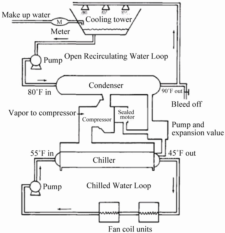 (b)
(b)
Figure 4. (a) 3-D typical combinations of closed and open systems [3]; (b) Typical combinations of closed and open systems [4].
the water in an insoluble form, such as silt, oil, process contamination, or biological masses. Deposits are most often an accumulation of sediments or settled solids that drop out at some point in a system where the water velocity falls to a level too low to support the material in the stream [4]. Deposits can occur in any type of water conduit, water-using device, or storage vessel. They occur in boilers as well as in distribution systems and heat exchangers. In this paper, those deposits forming in industrial cooling systems and industrial and municipal distribution systems are concentrated. The source of potential depositing material may be external or internal to the system. One of the most prominent external sources is the water supply itself, which may contain suspended solids, such as silt in a turbid surface water, soluble or precipitated iron, manganese, or carryover from a clari-
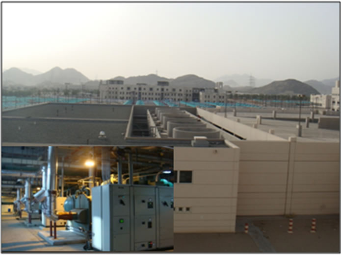
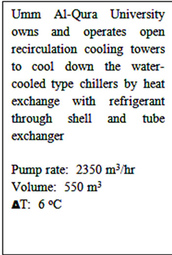
Figure 5. Open recirculation cooling towers at UQU.
fier or other pretreatment unit. A second source of depositing materials, particularly in an open recirculating cooling system with a cooling tower, is air [4]. Cooling towers act as large air scrubbers, and the water is quite effective in capturing dust, microbes, and other debris from the large volume of air that it contacts [2]. Because the amount of suspended solids in air is always changing, the suspended solids level in the circulating water also changes considerably with time; seasonal variations are common, depending on local environmental conditions [4]. Atmospheric sources contribute significantly to deposits in arid sections of the country, near farm lands, and in areas of high prevailing winds [4].
3) Microbiological Contamination: cooling water systems provide an ideal environment for bacteria to grow, multiply, and cause deposit problem in condenser of the chillers [4].
3.2. Water Treatment Chemicals
3.2.1. Corrosion Inhibitor
Corrosion Inhibitors are classified as [4]:
1) Anodic corrosion inhibitors: Anodic corrosion inhibitors function by interfering with the anodic reaction to break the electrochemical circuit. In order to inhibit corrosion, anodic inhibitors must reduce the rate of dissolution of the metal.
2) Cathodic corrosion inhibitors: Cathodic inhibitors prevent the reduction of oxygen at the cathode. They reduce the corrosion rate by forming a barrier film on the metal, restricting oxygen reduction at the cathodic sites.
3) Typical corrosion inhibitors:
• Principally Anodic: Chromate, Nitrite, Orthophosphate, Bicarbonate, Silicate, and Molybdate;
• Principally Cathodic: Carbonate, Polyphosphate, Phosphate, and Zinc;
• Both Anodic and Cathodic: Organic Filmers.
3.2.2. Scale Inhibitor
Scale inhibitors and dispersants may be needed to prevent deposition of minerals in the water, depending on the water chemistry and the system conditions. Stabilized phosphate programs were among the first effective, nonchromate programs. The key to their success depends on polymers that can stabilize calcium phosphate in cooling water systems. The version of the stabilized phosphate program that operates at neutral cooling water pH depends on close control of the system pH as well. The programs are a blend of orthophosphate, polyphosphate, phosphonate, and polymers that provide scale inhibition [4]. Scale inhibitors can be classified as:
1) Organic Phosphorus Compounds These are most commonly used to prevent calcium and iron-based scales in open recirculation systems. In general, 0.5 - 6.0 ppm organic phosphorus (as PO4) will provide sufficient inhibition of calcium carbonate or calcium sulfate. Products are formulated to assure sufficient levels of scale inhibitor.
2) Polymer Acrylates The most common scale-inhibiting Acrylates are polymers based on acrylic acid or methyacrylates and perform best when molecular weight is around 1000 - 30,000. Their primary benefit over phosphorus based compounds is that they do not break down to orthophosphate to contribute to scaling potential. They are easily degraded in waste treatment plants by microorganisms and are therefore more environmentally acceptable.
4. Cooling Water Chemical Treatment Control Methods
4.1. Old Method (Traditional Chemical Controllers)
Most water treatment programs include a number of chemicals for treating corrosion, scale, fouling, and microbiological problems. These chemicals are prescribed for each individual system, based upon its unique characteristics. These chemicals must be fed within their recommended dosage range for maximum effectiveness to be obtained. The concentrations of treatment chemicals in the recirculation cooling water must be checked frequently and regularly. In this method, a cooling tower controller that controls water conductivity, pH, ORP, chemical injection rate based on blow down or make-up water rate, biocide injection on timer basis, with no software to relate all these parameters together will have these drawbacks as stated by [6]:
• Remote control, lagging in time;
• No logic control;
• Set points still rarely changed, once set;
• Added PLC integration;
• Still no stress control (scale-bio);
• Still no on-line performance monitoring;
• Some corrosion measurement with cupons.
4.2. New Method (Dynamic Automatic Chemical Treatment Controller)
To overcome the drawbacks of the old method adynamic automatic chemical treatment controller such as 3D TRASAR® was implemented in the chilled water plant number (1). 3D TRASAR® products are part of an innovative water treatment program that uses proven technology to prevent operational problems. 3D TRASAR compensates for both routine and special causes of system variation. 3D TRASAR programs provide a return on user’s investment through their unique control and diagnostic capabilities. 3D TRASAR technology as described by [1,8] is a combination of:
• Chemicals and proprietary tracers;
• Equipment;
• Diagnostics;
• Value-added service.
When properly applied, TRASAR can improve control, accuracy and system reliability, resulting in significant operational savings, while providing valuable system information. The features of 3D TRASAR [1,7,8] are:
1) Unique new measuring and controlling device: All important parameters are measured, controlled and logged.
2) New chemistry: The active component for preventing deposits and fouling is traced. Every second it can be measured by the 3D TRASAR Controller. Also, new environmental friendly corrosion protection is provided.
3) New software: New developed software to calculate the most optimal water treatment and determine operating window.
The main concept of the TRASAR is that its chemistries contain uniquely fluorescing molecules that allows the patented 3D TRASAR on-line fluoro-meter by NALCO to detect exactly how much chemical has been fed in order to determine residual which will result in accurate control of chemical levels in the cooling system under investigation [7].
The 3D TRASAR on-line fluoro-meter consists of a “flow cell”, an LED light source, filters, and detectors. The filters and detectors are turned to specific light frequencies unique to NALCO products and resultant process reactions. To measure the chemical properties of the flowing water in a reliable and repeatable method the LED light source is used which designed to have extremely bright light at the appropriate frequencies [7].
The simple on/off control schemes and timers were used for typical cooling water controllers to maintain pre-determined set points trying to avoid operational upsets. The pre-determined set points are only suitable for one set of stress conditions because as system stresses change, scale can form, bio-populations can multiply, and corrosion can occur without ever being detected [7]. The 3D TRASAR controller takes a revolutionary proactive approach to managing cooling system. Patented state of the art technology is used to prevent scale formation, control bio-population levels and continuously.
Monitoring corrosion rates through a unique integrated scheme which consist of [7]:
• 3D TRASAR scale control
• 3D TRASAR bio-control
• NCM corrosion monitoring technology with the 3D TRASAR innovative technology
as shown in Figure 6 the chemical treatment control is moved from the traditional way to real time control (leading in time action) using the TRASAR technology without any relation to the system parameters like conductivity.
5. Experimental Setup
The 3D TRASAR controller was installed in the plant (1) to service plant (1) to serve its condensers 1, 2, 3 as shown in Figure 7. Sample line taken from return condenser water line and inlet to 3D TRASAR controller, the outlet of sample water used as blow down water to control cooling tower cycles of concentration (COC). Typical installation of the 3D TRASAR is shown in Figure 8. Figure 9 shows the system controllers which can control chemical concentration, scale rate, corrosion rate microbiological growth, cooling water dissolved, and solids water to drain (water losses). The 3D TRASAR analyzes water treatment parameters and acts accordingly by providing control signal to chemical dosing pumps and blow down valve.
To explain the operation of an evaporative system under investigation the following parameters which were introduced by [2,4] are adopted.
Recirculation rate ( ): It is the flow of cooling water being pumped through the entire plant cooling loop.
Temperature differential or range ( ): It is the dif-
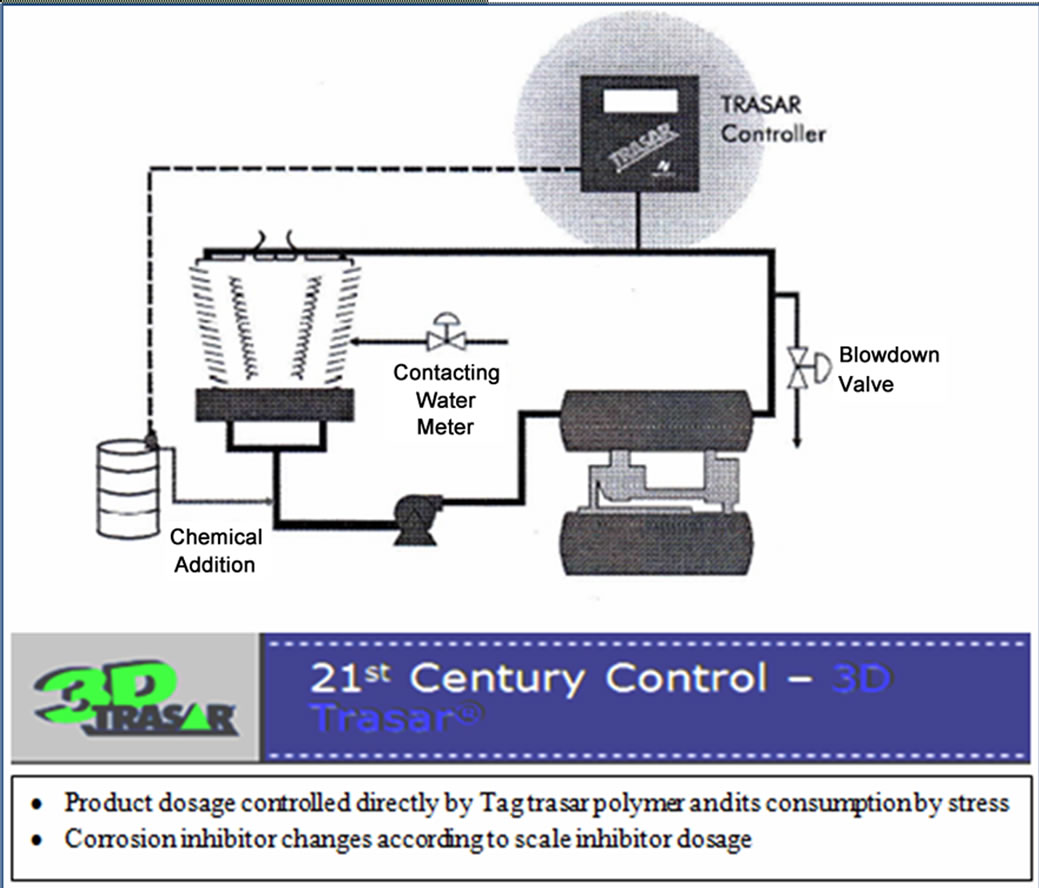
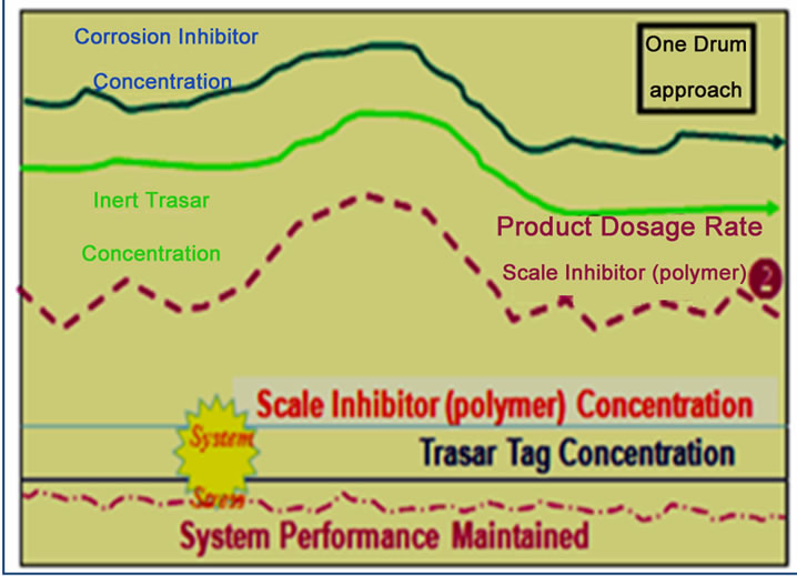
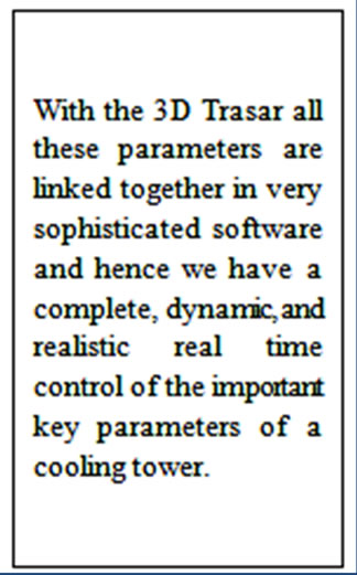
Figure 6. Cooling tower parameters linked through 3D TRASAR [1,8].
ference between the average water temperature returning to the tower from the plant exchangers ( ) and the average water temperature following evaporation (
 ) tower basin.
Evaporation ( ): It is the water lost to the atmosphere in the cooling process (
 ). The evaporation rate is dependent on the amount of water being cooled (
 ) and the temperature differential,
 . As a rule of thumb, for each 5.6˚C temperature drop across the evaporation process, 1% of the recirculation rate
  is evaporated. The recirculation rate
  is given by
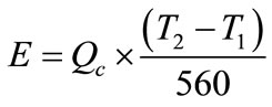 (1)
(1)
The amount of evaporation that can place over a given tower is limited primarily by the relative humidity of the air. Relative humidity is determined by measuring the wet and dry bulb temperature of the air.
Makeup ( ): The input of water required to replace the water lost by evaporation plus that being lost though blowdown, tower drift, and other miscellaneous losses. It is usually measured by a flow meter, if not it may be calculated as shown:
 (2)
(2)
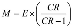
Concentration ratio ( ): Makeup to a recirculation cooling water system contains dissolved impurities. The evaporating water produces pure H2O vapor, leaving behind these impurities. The ratio of the concentration of salts in the circulating water (
 ) to those of the makeup
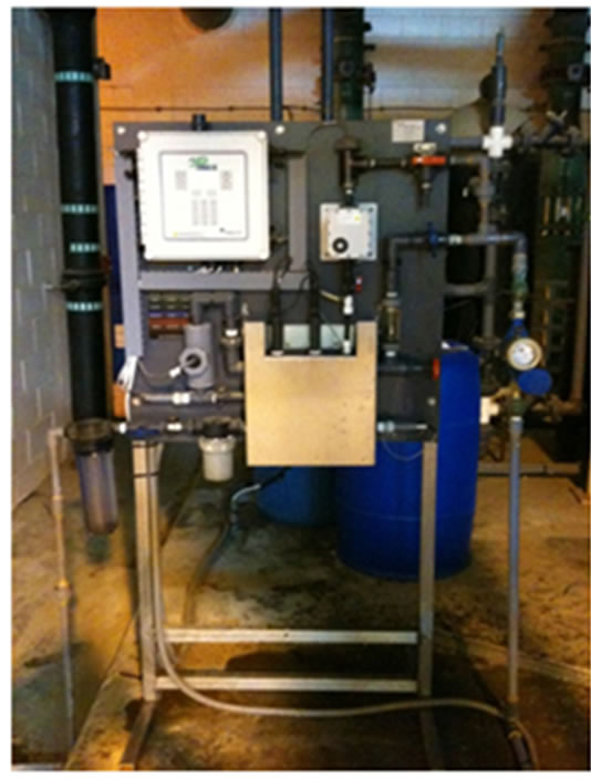
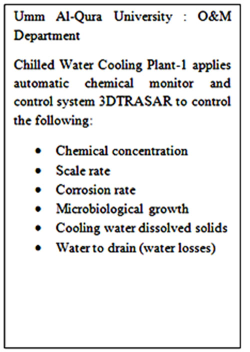
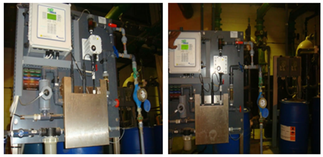
Figure 7. Photo of experimental set up of 3D TRASAR at UQU chilled water plant number 1.
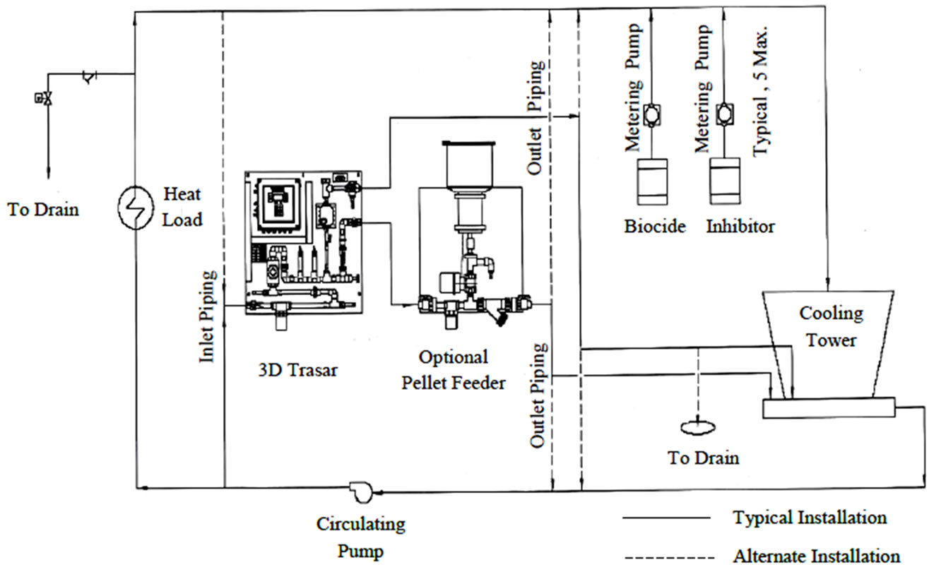
Figure 8. Typical instulation of the 3D TRASAR in the chilled water plant [1].
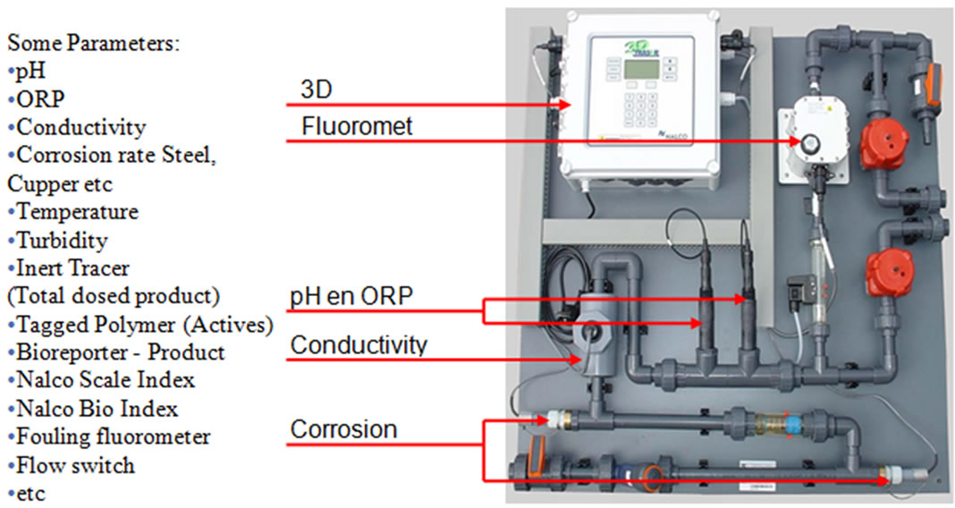
Figure 9. 3D TRASAR Controllers [8].
( ) is the concentration ratio.
 (3)
(3)
Since the input solids must equal the output solids,
 (4)
(4)
where  is the makeup flow and
  represents loss of concentrated water. Therefore, the concentration ratio is also
 (5)
(5)
The  can be calculated for several individual components of the water to determine if the system is in balance. In the ideal case, the system is in balance when the
  of all ions in the water (Ca, Mg, alkalinity, etc.) are equal.
Blowdown ( ): Since pure water vapor is discharged by evaporation, the dissolved and suspended solids left behind concentrate. If there were no water loss other than evaporation, these solids would concentrate to brine, causing massive scale and corrosion. To balance this, condenser water purposely discharged from the system to control concentration solids or other impurities in the water. This bleed-off (
 ) is calculated and controlled to remove solids at the same rate at which they are introduced by the makeup. There are other uncontrolled losses from the system: drift (
 ) and system losses (
 ). Therefore the total blowdown is
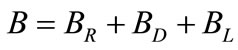 (6)
(6)
Blowdown is related to other factors thus:
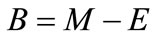 (7)
(7)
where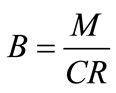 .
.
Drift ( ): They are un-evaporated water droplets (mist) that are lost from the cooling tower. A usual drift loss in conventional cooling towers is in range of 0.05% to 0.2% loss based on the recirculation rate. However, a very well design mist and drift eliminators is added in the modern cooling towers to reduce this droplets to about 0.005% of the recirculation rate.
System losses ( ): Losses from circulating water due to leakages from the plant equipments such as pumps, valves, and piping network or draw-off for such uses as equipment or floor area wash-up.
Holding capacity of system ( ): The holding capacity of system can be obtained by calculating the volume of water in the basin and adding an extra 20% to 30% for the water contained in the lines and equipment.
Time/cycle ( ): One cycle is defined as the time required for water to make one trip around the circulating loop. This time is a function of the holding capacity and the recalculating rate:
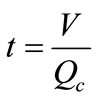 (8)
(8)
Holding time index ( ): It indicts the half-life of a treatment chemical added to an evaporated cooling system. Mathematically, this index represents the time required to dilute an added chemical to 50% of its original concentration after the chemical addition is discounted. It is also the time required to concentrate the makeup solids by a factor of 2. This is an important factor in setting control limits where chemical feed may be interrupted. It is also important for establishing an effective dosage for biological agents, which are slug fed into the system.
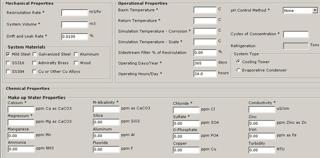
The plant data, operational parameters, and water quality were supplied to the new software 3D TRASAR which intern recommend the optimal program for the cooling condenser to maintain the plant free of scale, corrosion and bacteriological contaminants. Through the software certain key performance indicators such as chemical and water consumption, power, energy saving, and maintaining system integrity and efficiency will be monitored. Figure 10 shows the performance summary and Figure 11 shows the input data and system summery screens for software 3D TRASAR. The design, simulation, and performance analysis of experimental setup was based on the [9].
6. Results
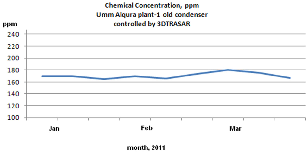
Applying 3D TRASAR programs (advanced automatic chemical treatment controller ) to central cooling plant (1) especially on condensers (1, 2 and 3), and selecting certain key performance indicators and monitoring such as chemical and water consumption, power, energy saving, and maintaining system integrity and efficiency. The discussion of the results was based on ref. [10] and 3D TRASAS reports which include; system summary, chemical summary report, Optimization report, Optimizer MOC survey report, and Optimizer calculated parameters report. The results are return on investment in terms of:
1) Reduced chemical consumption by avoiding overdosing
According to the below chemical concentration charts as shown in Figure 12 the overdosing due to manual chemical addition was reduced by 22%. The reduction in
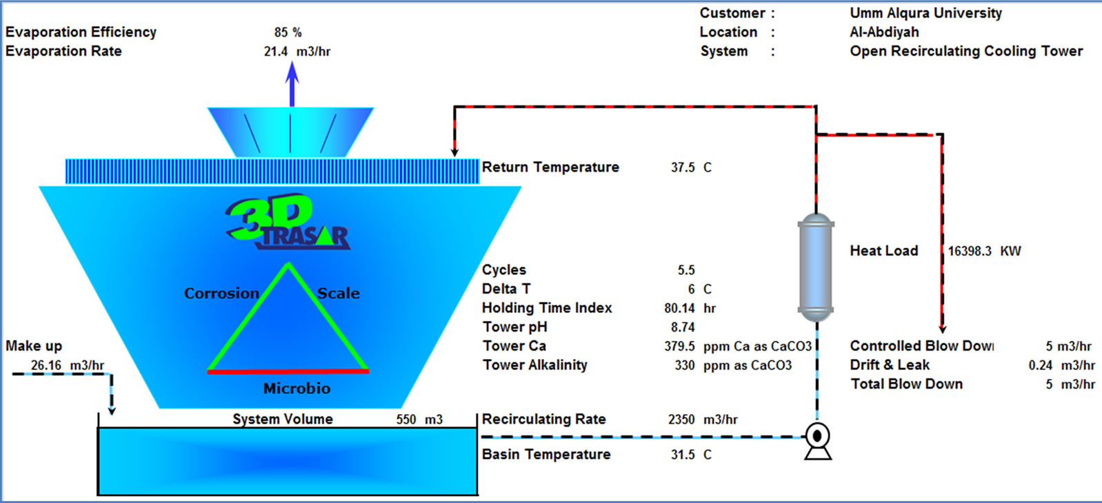

Figure 10. 3D TRASAR (sophisticated system of continuous, on-line, remote-accessible, cooling water treatment and performance monitoring) installed at UQU chilled water plant, software results [10].
 (a)
(a)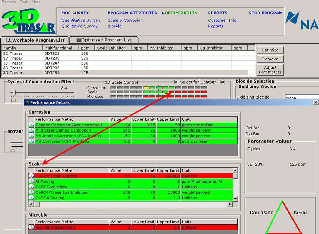 (b)
(b)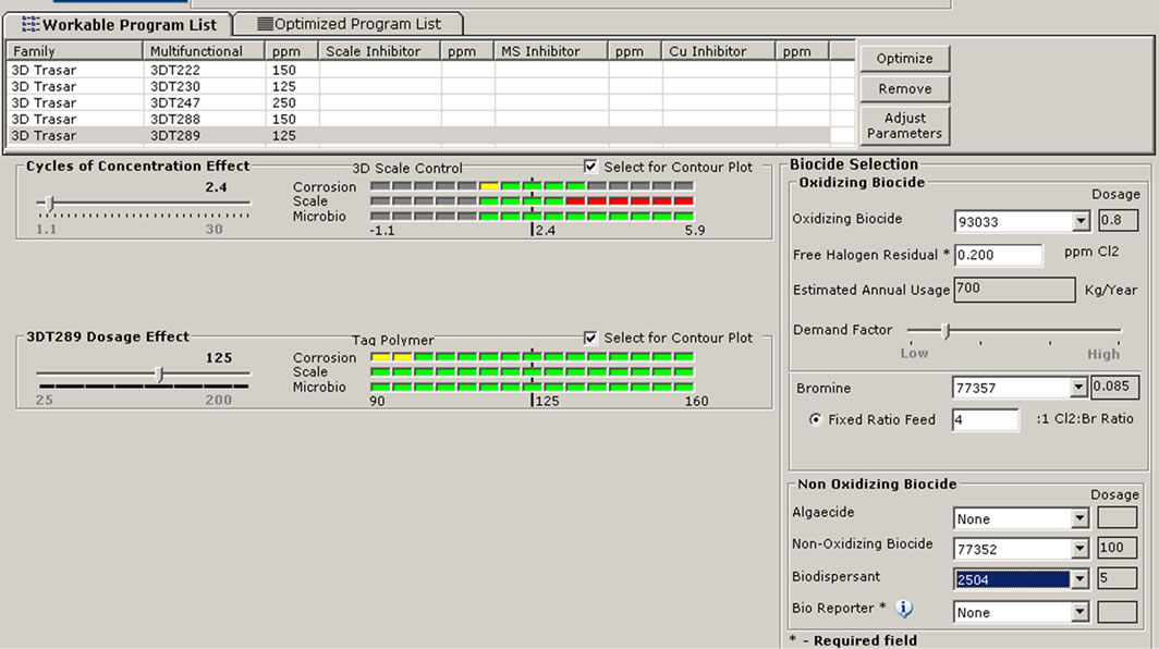 (c)
(c)
Figure 11. Snapshots of the 3DTRASAR software inputs and analysis enviroment [10]. (a) Input data; (b) Performance analysis; (c) Choice of biocides.
 (a)
(a)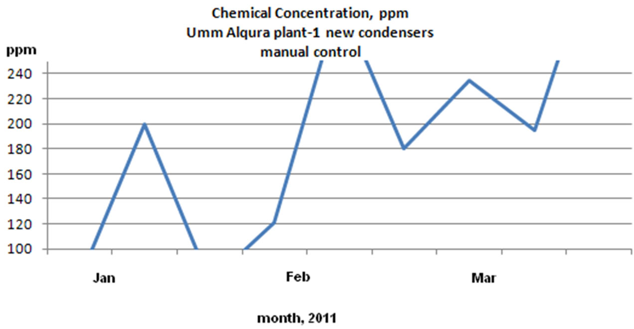 (b)
(b)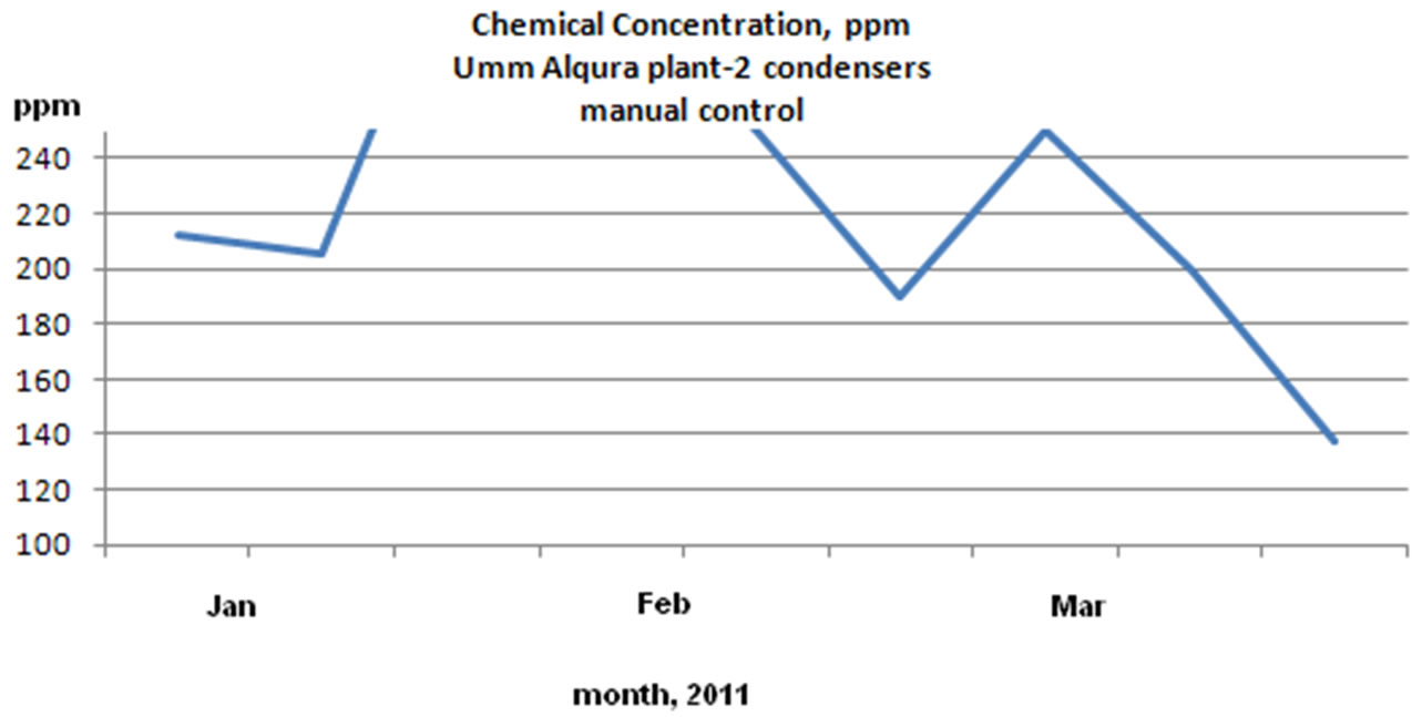 (c)
(c)
Figure 12. Chemical concentration (ppm) reading for UQU chilled water plants: 3D TRASAR control and manual control.
cost of treatment for one unit is estimated as USD 10,000/ year. Applying the same method for other units will increase the overall chemical saving.
2) Reduced water blow down (drain)
Cycles of concentration were increased to 4 - 5 COC in automatic control compared to 2.5 - 3.5 COC with normal treatment, this result in around 30% reduction on blow down water. The amount in terms of water volume is 14,600 m3/year; the price of cubic meter is USD 2/m3. Value of water saving is USD 29,200/year.
3) Eliminate fouling and scaling cost
Condensers operating with 3D TRASAR controller found to have clean tubes free from scales, other condensers show average scale formation of 2 mm thickness (see Figure 13). The saving of power consumption is estimated to be USD 9900/year for 3 chillers, based on 150 days/year operation and 3600 ton of refrigeration.
4) Eliminate chemical cleaning costs
Each chemical cleaning procedure costs the university O & M chemicals and labor. Manually controlled condensers run 1 - 2 cleanings per year, automatically controlled condensers run almost for one year with no chemical cleaning resulting in saving of around USD 9000/ year.
Also, Umm Al-Qura Operation & Maintenance Departments is looking further for reduction on water consumption by minimizing water to bleed (drain) and introduce the project of water reuse by using treated waste water as make up for cooling towers.
7. Conclusions
Cooling towers are very dynamic system, due to daily changes in makeup water quality, heat load and blow down water, it is very difficult to efficiently control chemicals concentration and system key performance indicators without innovative dynamic controller such as 3D TRASAR system that correlates all parameters together and take predictive action. Satisfactory results were obtained in terms of performance and cost of operation.
Because of environmental consideration, water cost and water availability, Department of Operation & Maintenance at UQU is looking further for reduction on water consumption by minimizing water to bleed (drain) and the project of water reuse by using treated waste water as make up for cooling towers. To achieve this objective, we believe that we need to use sophisticated system of continuous, on-line, remote-accessible, cooling water treatment and performance monitoring such as 3D TRASAR.
8. Acknowledgements
I would like to thank Umm Al-Qura University, Department of Maintenance and Operation, and Nalco Saudi Co. LTD. for their support. Special thanks go to Eng. Ashraf R., Naclo engineer, for his support.
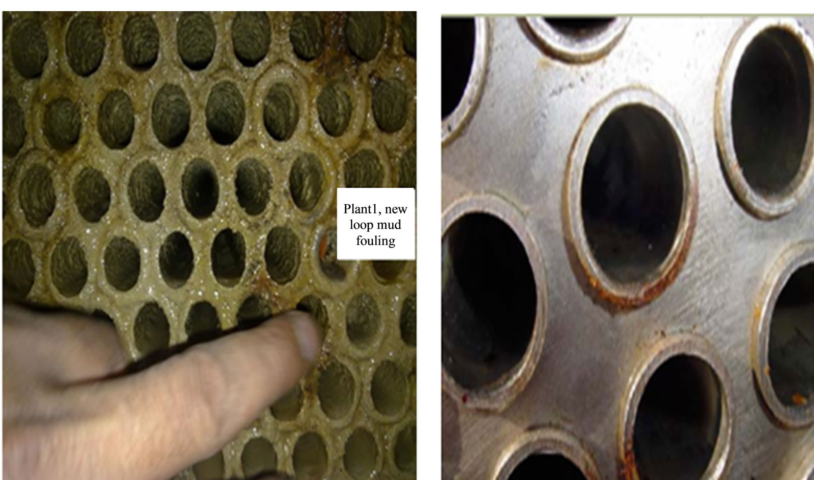
Figure 13. New loop mud’s fouling for chilled water plant number 1.
REFERENCES
- Nalco Training Course, “Cooling Water Treatment an Introduction,” Nalco Saudi Co. Ltd., Dammam, 2006.
- H. W. Stanford, “HVAC Water Chillers and Cooling Towers Fundamentals, Application, and Operation,” Marcel Dekker, Inc., New York, 2003.
- Veolia Water Solutions & Technologies, “Chemical Treatment in Cooling System, Veolia-Presentation-Water Treatment Chemical Program for UQU Chilled Water Plants Cooling System,” Umm Al-Qura University, Mecca, 2011.
- F. N. Kemmer, “The Nalco Water Handbook,” 2nd Edition, McGraw-Hill Book Company, New York, 1988.
- Nalco Engineer Example, “Cooling Water Operation Training Section Examples,” Nalco Saudi Co. Ltd., Dammam, 2005.
- R. Ashraf, “Private Communication,” Nalco Saudi Co. Ltd., Dammam, 2011.
- Nalco Company, “3D TRASAR® Instruction and Training Manual,” Nalco Saudi Co. Ltd., Dammam, 2006.
- Nalco 305 CHEN, “3D TRASAR® Installation and Operation Manual,” Nalco Saudi Co. Ltd., Dammam, 2006.
- N. V. Suryanarayana and O. Arici, “Design and Simulation of Thermal Systems,” McGraw-Hill Higher Education, New York, 2003.
- R. Ashraf, “3D TRASAR: Stress Management for Cooling Systems, Nalco Presentation-Water Treatment Chemical Program for UQU Chilled Water Plants Cooling System,” Umm Al-Qura University, Mecca, 2011.