Intelligent Control and Automation
Vol. 4 No. 1 (2013) , Article ID: 27843 , 8 pages DOI:10.4236/ica.2013.41008
H2 and H∞ Controller Design of Twin Rotor System (TRS)
1Center for Advanced Studies in Engineering, Islamabad, Pakistan
2University of South Asia, Lahore, Pakistan
Email: usman.ahmad@msn.com, waqas.anjum@iub.edu.pk, smab_engineer@yahoo.com
Received September 5, 2012; revised October 5, 2012; accepted October 13, 2012
Keywords: Robust; Optimal Control; TRS; MIMO; Linearization; Controller
ABSTRACT
Control engineering had been the core of all engineering fields all the time. As the name depicts, control of different parameters of various industrial or commercial equipment like plants, vehicles, aircrafts and etc is obtained. Robust and optimal control of these equipments plays a vital role. This paper presents a design of H2 and H∞ control for a Twin Rotor System (TRS). TRS is a multi input multi output (MIMO) nonlinear system. The main objective is to control the angular position of the lever bar of TRS. It is having strong coupling between inputs and outputs. The model is first linearized and then controllers are designed to control the positions of lever bar. Simulations are made in MATLAB/SIMULINK. Model parameters are also provided in the end.
1. Introduction
The question of Multi-Input-Multi-Output (MIMO) control has always been a thought-provoking sub-field surrounded by the field of control engineering. Among the systems that involve MIMO control, the helicopter rises out as one of the striking models. This kind of aircraft needs two rotors, spinning in perpendicular planes, therefore, cannot depend on Single-Input-Single-Output controllers to steer in the deep space. Also, un-manned helicopters have not yet been viewed in armies globally; this fact gives the job of designing MIMO control systems for helicopters a large space to stimulate [1].
The twin rotor system establishes the conventions of a nonlinear MIMO system with considerable cross coupling. Its operation approaches a helicopter but the angle of attack of the rotors is fixed, and the aerodynamic forces are regulated by changing the speed of motors. The entire mechanical model for this machine has been matured. Based on this mechanical model, various control designs are devised to control the apparatus using MATLAB-Simulink [2]. These control strategies are formed to prepare the Twin-Rotor system go to prearranged objectives and chase periodic input signals.
The exercise of scheming the control designs demands the author to do much labor on state-space formation linearization and exploratory works. Mathematical estimation is also executed to achieve the approximated polynomials for variables association. In most of the realistic control systems such as flight control systems, there survives saturation restriction on controller outputs
[3,4]. If a feedback controller intended without taking into consideration such restraint is employed the closedloop system may be inconsistent in the case where large external signal is supplemented. One method to treat with such a difficulty is to formulate a low-gain controller which does not outrage input limitations for all extrinsic signals that will be introduced. However, it is clear that this approach culminates in unprogressive control operation.
The TRS comprises of a beam centered on its core in such a way that it can gyrate freely both in the horizontal and vertical planes. At both ends of the beam, there are rotors (main rotor and tail rotor) steered by DC motors. A counterbalance arm with a weight on its end is rooted to the beam at the axis [5]. The state of the beam is characterized by four system variables: horizontal and vertical angles calculated by position sensors provided at the pivot, and two corresponding angular velocities. Two conventional state variables are the angular velocities of the rotors, regulated by tachometers linked with the DC motors [6].
In a standard helicopter, the aerodynamic force is regulated by varying the angle of attack. However, where the angle of attack is fixed then the aerodynamic force is controlled by varying the speed of motors. Therefore, the control inputs are supply voltages of the DC motors. A modification in the voltage use ends in a change of the spinning speed the rotor which culminates in a change of the complementary position of the beam.
To overcome the conservative design approach, different control approaches that employ on-line optimization have been introduced [7-9]. The state-dependent gain-scheduled control scheme [8,9] is one of the approaches. In this design a control rule which has an arrangement that a high-gain control rule and a low gain control rule are interposed by a scheduling parameter is employed. The scheduling parameter is settled by figuring out a convex optimization question on-line. The control law of [8,9] is formed established on the polytypic explanation of a saturation part of [10]. As a consequence, the control law can attain great section of charm even if the plant is unstable. This procedure is expanded to tracking control problems [11]. However, efficiency of these approaches are assessed only by way of numerical prototypes of linear systems whose sizes are miniature and have not been entrenched by experiments. In actual systems, there exist interferences, nonlinearities, unmodeled dynamics, and computational delay. These components may have severely damaging trappings on control performance. Therefore, to estimate the competence of the methods of [8,9,11] by experiments is quite important to put the methods to practical use.
The model of TRS is given in Figure 1. It comprises of a vertical axis A on which a lever arm L is connected by a cylindrical joint using an L shaped link. This L shaped link is made of two bars: one bar having a length h1 and the other having a length h2. These two bars are at right angles to each other. The bar h1 works as the horizontal axis. Two rotors are scaled on the lever arm: a main rotor and a tail rotor. The voltages u1 and u2 are the inputs to this model. A weight is mounted on an adjustable position towards the tail rotor.
2. State Space Model
In this section the linearized state space model of TRS is given. Nonlinear model of TRS is first linearized about its operating point. The operating point that we found solving the nonlinear state space equations of TRS is gi-

Figure 1. Model of TRS.
ven below
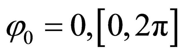
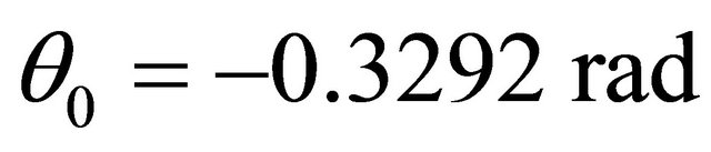


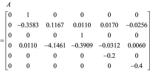
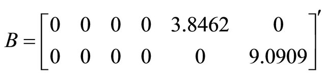
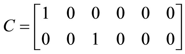
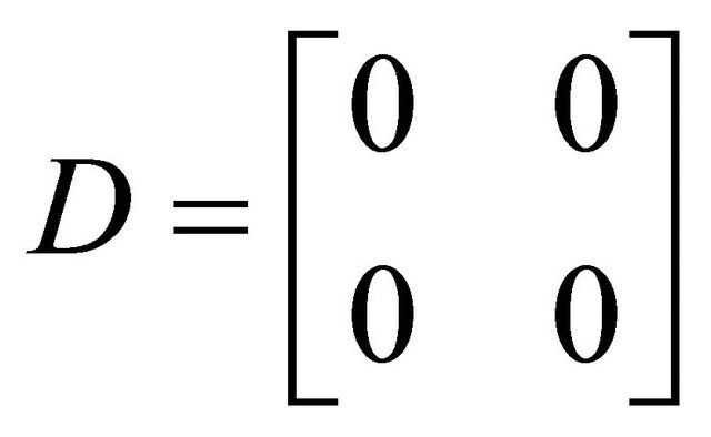
This operating point is found using the MATLAB command “trim”. Using this operating point in MATLAB we found the linearized model of TRS using the command “linmod”. The linear model is given below.
 (1)
(1)
 (2)
(2)
where
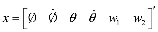
![]() = azimuth angle
= azimuth angle
![]() = azimuth velocity
= azimuth velocity
 = elevation angle
 = elevation velocity
 = angular velocity of main rotor
 = angular velocity of tail rotor

 = actuating signal
 = actuating signal

![]() = azimuth angle
= azimuth angle
 = elevation angle
This state space model will be used in next sections to design the different type of controllers for twin rotor system.
3. H2 and H∞ Controller Design
In this section we will be designing the H2 and H∞ controllers for twin rotor system. Before designing the optimal controllers we check the system response by designing a Linear Quadratic Regulator (LQR) using the MATLAB command “K = LQR (A, B, Q, R, N)”. The matrices Q and R are chosen by hit and trial method and it must be noted that the Q matrix must be semi positive definite and R matrix must be symmetric positive definite. The controller gain K that we got from LQR is given below.

The responses of the system with step input using this controller are given in Figure 2.
Linear simulation results are shown in Figure 3.
It is evident from the simulation results that the controller designed by LQR in MATLAB does not provide sufficient stability to the TRS system. As this does not provide the desired results so we move towards the design of H2 and H∞ controllers.
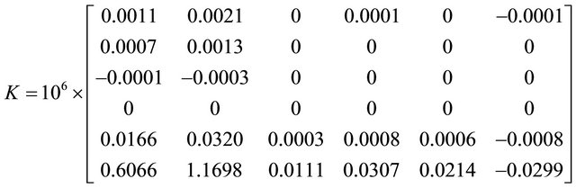
First we design the H2 controller for TRS. We know that this type of controller minimizes the cost function of the system while providing the supportive results. To design this controller we use the MATLAB command “[K, Tzw] = h2syn (P, Ny, Nu)” that gives us the controller gain K for our plant i.e. TRS system. Here P is the packed plant of our linear model, Ny is the dimension of output at Nu is the dimension of input. This controller is obtained after solving the Riccati equation. The controller obtained through this is given in the matrix below.
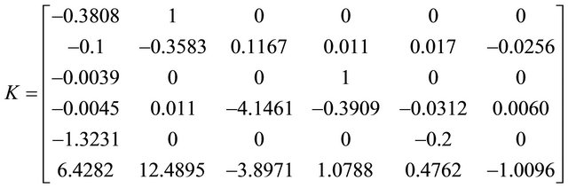

Figure 2. Step response with LQR.

Figure 3. Linear simulation results of LQR.
After getting this controller gain K we made a simulink model and ran the simulations. We set up the parameters according to our requirement of design. The simulink model and its responses are given in Figures 4 and 5.
The output y is obtained using scope 3, response of the plant is obtained using scope 2 and response of the controller is obtained using scope 1 in simulink model. Disturbances are also added in simulink model.
Simulation results show that the controller designed using H2 approach is robust and it stabilizes the plant in the presence of uncertainties. In comparison with LQR, H2 is much more robust and gives the desired result for
TRS. Although the overshoot is high but still it achieves a stable position after a certain settling time.
Now we design the H∞ controller like H2 controller. To design this type of controller we use MATLAB command

In this command P is the packed plant matrix, Ny and Nu are the dimensions of output and input, Gamamin and Gamamax are the minimum and maximum bounds of Gama and tol is the tolerance parameter. The controller obtained through this is
As we have achieved the controller gain for this controller, now we simulate the model. The simulink model and its responses are given in Figures 6 and 7.
The responses are given below.
Simulation results show that the controller designed using H∞ approach is robust and it stabilizes the plant in the presence of uncertainties. In comparison with LQR, H∞ is much more robust and gives the desired result for TRS. Deeply analyzing Figures 5 and 7, we come to know that the responses of both the controllers are robust and stable as after some time they achieve a stable value but in case of H∞ controller the output response shows

Figure 4. Simulink model for H2 control.
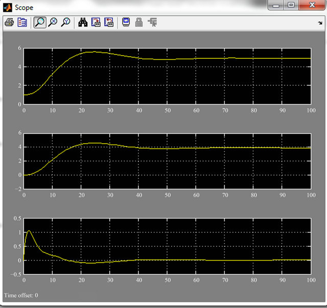
Figure 5. Simulation of simulink model with disturbances.
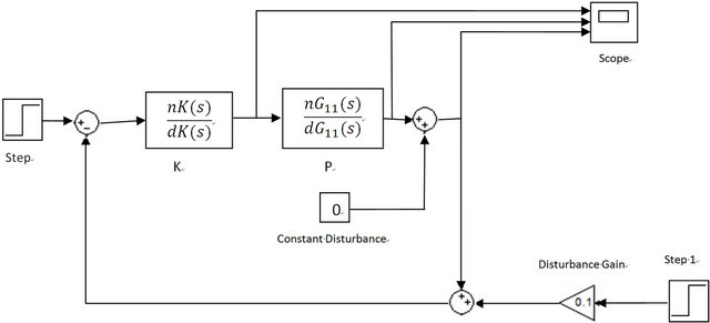
Figure 6. Simulink model for H∞ controller.
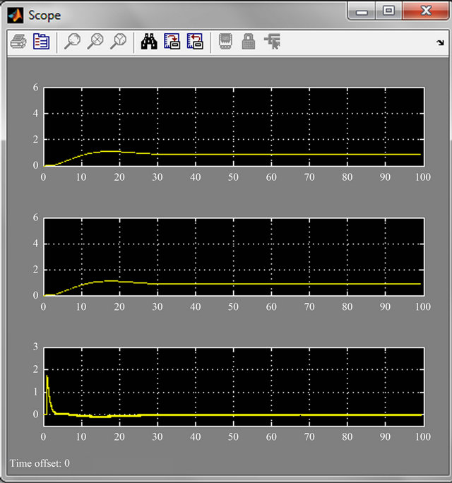
Figure 7. Responses of H∞ controller.
less overshoot as compared to H2 controller. So the design of H∞ controller is more suitable in the presence of disturbances as it gives less overshoot and settling time.
4. Conclusion
In this paper we have efficiently designed H2 and H∞ Controllers for a twin rotor system. Simulation results shown in this paper are the evidence that the controllers that are designed in MATLAB are robust enough that they can handle the plant with more efficiency when some disturbances are also present. In comparison with LQR, both the controllers provide stabilizing results and ensure that the plant will remain stable. Several graphs are shown in this paper that support the achievement of the said objective. Although the system in originally unstable and nonlinear but after linearization it can be made stable using the procedures of controller designs.
REFERENCES
- J. M. Maciejowski, “Multivariable Feedback Design,” Addison-Wesley Publishing Company, Boston, 1989.
- M. Gafven, “Modelling of rhe ETH Helicoprer Laboratory Process,” Department of Automatic Control, Lund Institute of Technology, Lund, 2001.
- C. Barbu, R. Reginatto, A. R. Teel and L. Zaccarian, “Anti-Windup Design for Manual Flight Control,” Proceedings of American Control Conference, San Diego, 1999, pp. 3186-3190,.
- M. Pachter and R. B. Miller, “Manual Flight Control with Saturating Actuators,” IEEE Control Systems, 1998.
- M. Sacki, J. Imura and Y. Wada, “Flight Control Design of Twin Rotor Helicopter Model by 2 Step Exact Linearization,” Proceedings of IEEE International Conference on Control Applications, Vol. 1, 1999, pp. 146-151.
- G. Mustafa and N. Iqbal, “Control Design for a Twin Rotor Helicopter Model via Exact State Feedback,” INMIC Proceedings of the 8th International Multitopic Conference, Lahore, 24-26 December 2004, pp. 706-711.
- F. Allg¨ower and A. Zhen, Eds., “Nonlinear Model Predictive Control,” Progress in Systems and Control Theory, Vol. 26, 2000. doi:10.1007/978-3-0348-8407-5
- N. Wada and M. Saeki, “An LMI Based Scheduling Algorithm for Constrained Stabilization Problems,” Systems & Control Letters, Vol. 57, No. 3, 2008, pp. 255-261. doi:10.1016/j.sysconle.2007.09.006
- N. Wada and M. Saeki, “A Scheduling Algorithm for Constrained Control Systems: An Approach Based on a Parameter Dependent Lyapunov Function,” Proceedings of American Control Conference, New Orleans, 2007, pp. 5200-5205.
- T. Hu and Z. Lin, “Control Systems with Actuator Saturation: Analysis and Design,” Springer, Berlin, 2001. doi:10.1007/978-1-4612-0205-9
- N. Wada and M. Saeki, “Tracking Control with Saturating Actuators: A Method Based on State-Dependent GainScheduling and Reference Management,” Proceedings of 17th IFAC World Congress, Seoul, 2008.
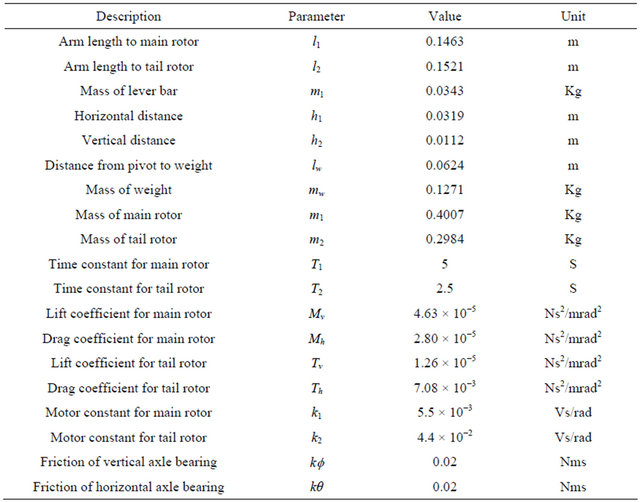
Simulation Parameters
The parameters that are used in simulations to obtain the linear state space model of twin rotor system are given below.