Journal of Modern Physics
Vol.2 No.12(2011), Article ID:9037,26 pages DOI:10.4236/jmp.2011.212183
Quantized Energy Momentum and Wave for an Electromagnetic Pulse—A Single Photon inside Negative Refractive Indexed Media
Reactor Control Division, Bhabha Atomic Research Centre (BARC), Mumbai, India
E-mail: shantanu@barc.gov.in
Received August 1, 2011; revised October 9, 2011; accepted October 20, 2011
Keywords: Negative refractive Indexed Material (NRM), Group Refractive Index, Phase refractive index, Wave momentum, Mechanical Momentum, Reactive energy
ABSTRACT
An Electromagnetic (EM) radiation in dispersion less free space vacuum is represented by a photon, with corpuscular and wave nature. The discussions, for the past century aimed at the nature of photon inside a media having dispersion in the refraction property, other than free space. What about its nature if the space be of refractive index which is negative, is discussed in this paper. We call mechanical momentum, wave-momentum, and try to match our present theories with intriguing property of this “photon” or pulse carrying EM energy packet, and more so we try to find its property energy, momentum inside a media a positive refractive media, and if the media show a negative refractive index behavior, then these queries are profound, and suitable explanations to these classical concepts of corpuscular-wave nature of photon inside these media are quest for the scientists dealing with these materials having negative index of refraction. Here some of this counterintuitive nature of corpuscular-wave nature of photon inside negative indexed material is brought out, with possible “new definition” of its “wave-momentum”, the concept of “reactive energy” inside negative indexed material, along with possible “new wave equation”. These definitions and expressions of “wave-momentum” and “reactive energy” pertaining to negative indexed material are new and discussed and derived by classical means.
1. Introduction
We have demonstrated negative refractive index “metamaterial” NRM plasmonic structures in Ka-band. In our experimental investigation, we have made these plasmonic meta-material prisms of 45, 30 and 15 degrees to get enhanced transmittance of more than 15 dB from background; at negative angles indicating a refractive index of about –1.8, [1-7] .This paper is not aimed for this experimental design, where the meta-material realized by us is based on simple wire-array and Labyrinth resonators, [1-7], but to focus on possible theory of the wave mechanics coupled to particle nature of the EM radiation, energy and momentum transport anomalies, a possible new momentum energy description, for a “single” radiation pulse, single photon. Also in our repeated observations on numerical experiments we get, as to if a pulse of EM radiation is launched inside a negative refractive index material (NRM), gets squeezed sharpened advanced, [1-7]. Though several approaches to explain these counterintuitive phenomena have been evolving, yet it is interesting if in the negative refractive index (NRM) parlance particle-wave theory be re-visited. Here we give possible classical explanations to these counterintuitive phenomena and also a new explanations regarding energy momentum, wave equation if applied to this negative indexed material: how shall they look, vis-à-vis positive indexed systems. We propose the concept of reactive energy and expression for new wavemomentum for pulse of electromagnetic energy inside a medium (negative refractive indexed), with suitable derivation along with new wave equation. The research papers [8-10], discussed momentum and energy of this reversed electrodynamics in other contexts. Herein we are deriving the similar concepts with different approach, limiting to propagation of EM pulse inside NRM for a single photon.
The paper is organized in several sections. The section 2 discusses the observation of an electromagnetic pulse (a single photon) as it enters NRM region, from free space. This section also deliberates how an electromagnetic pulse is formed as modulation of slowly varying message signal wave with a carrier frequency signal wave, and deliberates classical energy momentum concept and phase and group velocity aspect. The sections 3 and 4 revisits the dispersion of refractive index and defines phase refractive index and group refractive index, and its relation to our negative refractive indexed material (NRM) and observations. In the sections 5, 6 and 7 we present via a thought experiment about meaning of equivalence of constant quantity  to a quantity which is a product of phase and group velocity. We elaborate where they are equal that in wave guides and its similarity in quantum mechanics expressions. We use these developed concepts and apply them in the expression of total energy to get the expressions for mechanical momentum, wave-momentum inside dispersive media and with media of NRM, in section 8. Section 9 is devoted to bring out quantization of electromagnetic energy and momentum via Milloni’s quantization technique, [11] to Minkowski’s [12] and Abraham’s [13] definition of photon momentum; for a single “dressed” photon case, while photon is in dispersive non-magnetic dielectric media. In section 10 we discuss signal of reflection and transmission for a single electromagnetic pulse (photon) from NRM region, and state that the pulse entering the NRM should be termed as negative photon. We show that its character, inside NRM to a normal photon is different, and give a new definition to its wave-momentum, in section 11. We discuss the momentum transfer concepts of this single photon in NRM in section 12, and state that the Minkowski [12] and Abraham momentum [13] are mechanical or corpuscular in nature, while wave-momentum has to be defined separately; and we formulate the same, with justification. We also show here results of the method of momentum transfer via reflection and transmission probabilities are same that we had obtained via method of total energy description by use of
  as product of phase and group velocities in section 8. In section 13 we give interpretation to active and reactive energy concepts representing corpuscular and wave energies respectively, and their manifestations in NRM. From this concept we also bring out the description of corpuscular and wave momentum of single photon. Section 14 we give possible new Quantum-prescriptors to be operated on wave function to get a modified Schrodinger wave equation to represent NRM. Lastly we conclude our findings followed by list of references.
2. Observing Electromagnetic Pulse Propagation inside Negative Refractive Indexed Material
A wave with crest and trough moving and carrying a Gaussian pulse a “packet” of energy, in free space travelling with speed of light , (refer figure 1(a)) when entering the NRM with phase refractive index
 , will retard the wave-packets (group of frequencies) speed to
  (the
(the  being group refractive index) in this case
 , (refer figures 1(b) and (c)) though the direction of travel of wave-packet, energy will be in same direction as was in free space; but the phases crests and troughs will here start travelling in opposite to freespace with phase velocity
 . The group velocity of the signal in this case is
 . This is implication of the phase and group refractive index in NRM. This we elaborate in next sections.
The implication at NRM boundary of these opposite phases meeting will form a “cusp” which be oscillating at the junction of NRM to the free space (refer figure 1(b)) [6,7,14-20]. This phenomenon of retardation of the wave-packet envelope and change of direction of travel of crest & trough the phase, inside NRM gives the “pulsesharpening” effect, and flattening of wave-front effect, what we have been observing in our experiments [6] also, [18-20] (refer figure 1(c)).
The cusps at the NRM boundary is due to counter propagation of the “phases” of the waves inside and outside the NRM, they are surface charges, and at the boundary Electric Field at this cusp oscillates, [6,7,18-26] as two sets of impinging wave fronts meet at the interface with ENG (Epsilon Negative Material ). The same cusp will be obtained for the MNG, (Mu Negative Material
 ) and it may be argued that “surface” currents in that case for TE polarized incidence, will be at the boundary and magnetic field at the cusp then will oscillate, [6,7,18-26].
However, these points are valid when the wave hits a slab with ENG and MNG i.e. NRM here however there will be propagating modes inside NRM-from evanescent [6,7,18-26]. In the case of Double Negative slab (NRM) there will be cusp formation at the boundary too. The formation of surface states or excitation of surface Plasmon poalriton is altogether different field in modern optics, where matching of wave vectors and phase velocities are mandatory, we will not deal with this subject here; however this is important.
Let a single electromagnetic pulse (a single photon) be travelling in free space. Observer sitting on the crest and another observer sitting on the envelope, travelling in free space they will find themselves at rest with respect to each other (Figure 1(a)). While the packet (single
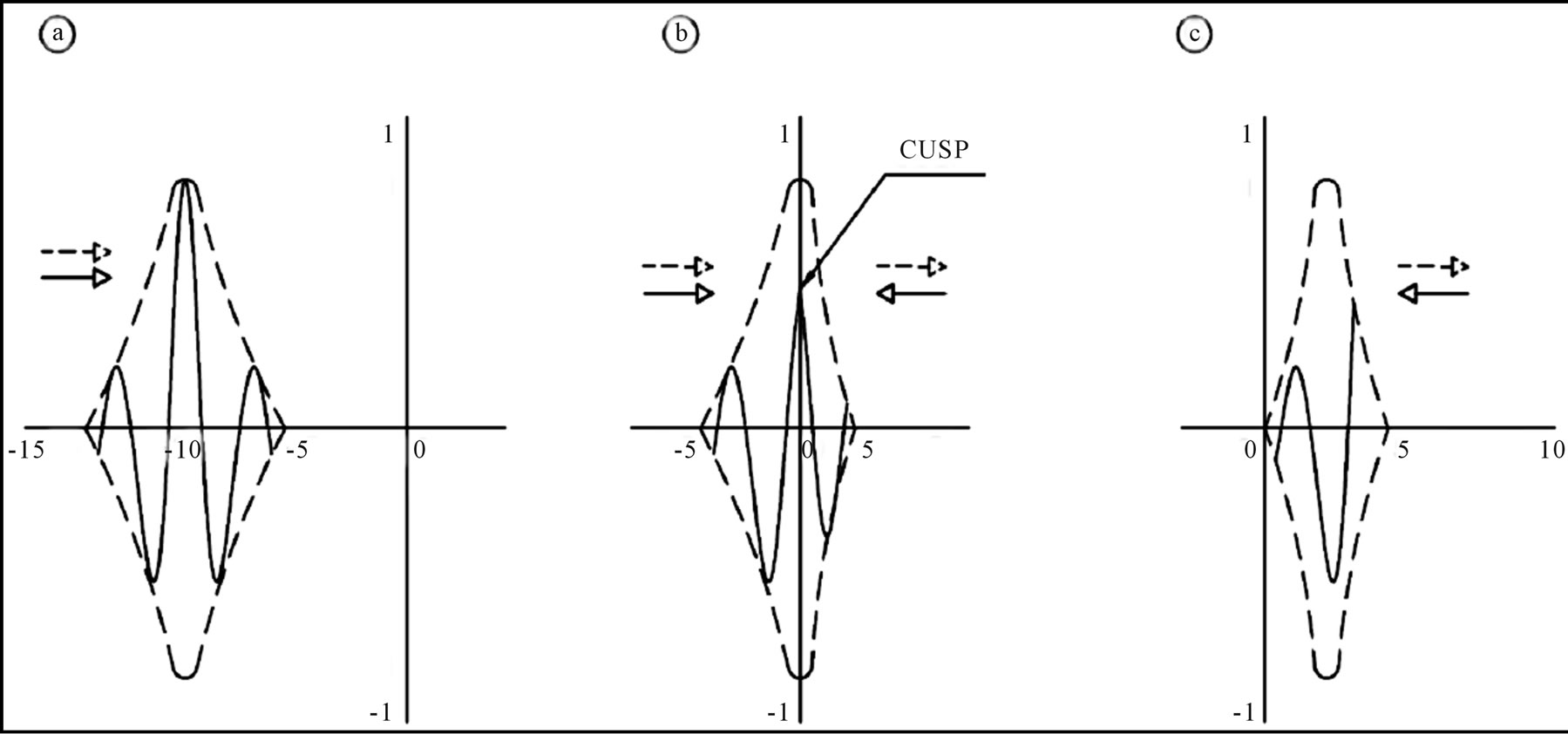
Figure 1. Propagation of electromagnetic pulse. (a) Pulse propagating towards right in free space, having envelope (dashed) and phases (solid) traveling with velocity c in same direction; (b) The same pulse touches the media with NRM with phase index as −1, and group index as +3; shows that at the boundary there is “cusp” formation and envelope retards. Here the phases travel in opposite direction and the group (envelope) travels in same direction. This cusp oscillates at the surface of the NRM boundary; (c) The pulse is traveling as envelope with squeezed envelope inside NRM towards the right direction with velocity +c/3 whereas the phases are traveling opposite to envelope, with velocity –c. The pulse is sharpened and squeezed. This is ideal case of loss-less NRM while lossy structures will have attenuated pulse as it travels.
photon) enters the NRM, the two observers will find that they are moving away from each other (Figure 1(c)).
This is this nature of wave-momentum that is generator of infinitesimal translations, and the infinitesimal translations of the “waves” corresponds to motion of its crests and troughs, and in NRM “opposed to” the direction of motion of radiation. It is for this reason the wavemomentum points in the opposite direction to the mechanical momentum inside NRM. We will deal with these aspects that are momentum (corpuscular, mechanical, and wave) for a single photon in NRM.
One can demonstrate backward wave, by a strip-line circuit presented in figure 2. The LHM is being emulated via circuit techniques of strip lines, where the output peak appears to arrive before the input peak; giving idea of faster than light propagation. This technique is called Periodically Loaded Transmission Line (PLTL) depicted in figure 2. Here there is anomalous dispersion giving negative regions in dispersion characteristic [6] thereby giving similar effect of Negative Indexed Material.
The figure 3 gives an idea what is an electromagnetic pulse. We shall relate corpuscular and wave nature to the same. The probability amplitude is what is of interest to say where the particle ought to be at space-time. Amplitude to find a particle (photon) at a place can in some circumstances, vary in space and time in a manner say , where
  is the frequency, which is related classically to energy by
 , and
, and  -the wave number, is related to momentum through
 . In the figure 3 the carrier wave frequency is 0.9 G Hz, thus
 .We would say the particle (photon) had a definite momentum,
  if wave number
  were exactly that particular wave number (without any spread or uncertainty); that is a perfect wave, which goes on with same amplitude everywhere. The amplitude equation as described, then gives amplitude and probability (square of amplitude) for finding particle (photon) as function of space-time. Thus for a perfect wave the probability is constant which means probability to find particle (photon) is the same anywhere. This is not the situation with single particle (photon) travelling as in figure 3. The amplitude modulated pulse as shown has maxima and dies out at both the sides. It was possible to get this by adding waves of nearly same
  and
and , in figure 3 signals of 0.89 GHz and 0.91 GHz were added to get the electromagnetic pulse a single photon. Thus the particle (photon) is more likely to be near the maxima (lump) of figure 3. After a few moments this wave with lump will be elsewhere, as it is traveling with group velocity
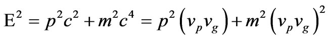
 , should be related to particle (photon) velocity. We have classical Energy momentum relativistic expressions as
 , and
, and
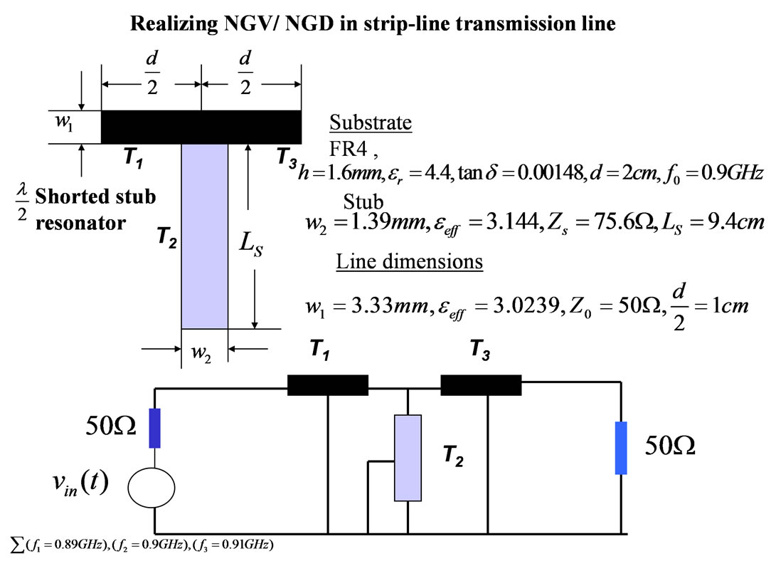
Figure 2. Periodically Loaded Transmission Line PLTL to make LHM.

Figure 3. Input output response to have a feel of “faster than light” propagation through LHM.
 . Eliminating
  from these two expressions lead us to
 . This relation is depicted in figure 4, and will be used in subsequent sections. The
  is related to
  and
and  is related to
 , using them in the total energy expression of above we get
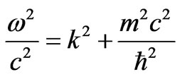
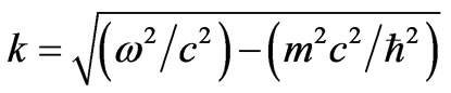
 , a quantum-mechanical relation between frequency and wave number, for a quantum-mechanical amplitude wave representing a particle of mass
 . From this derived expression we get
 , which gives phase velocity
 , as
, as . Differentiating, and substituting several related quantities we obtain expression of the group velocity as
 .
.
Recognizing that , we say that group velocity of the wave packet is particle velocity v. Here we have a special case as
 , which in general need not be equal, but are equivalent. This we shall deal in section 5 and use this concept further to arrive at momentum

Figure 4. The Energy Diagram for corpuscular and phase (wave) energy in free space.
and energy transfer to medium, by a single photon.
3. Phase and Group Refractive Index Revisiting for Negative Refractive Index Material
Let us demarcate the two refractive indices, [14,15], and [16,17,27] and this demarcation is essential for explaining the NRM theory. This concept is revisited here particularly to stress the Negative Refraction phenomena.
Take the refractive index dispersive that is a function of frequency call it  call it phase refractive index. This is basic refractive indices by which the velocity of phases of traveling gets modified inside a dispersive media. This we call phase index
 . Similarly velocity of a group of frequency travelling wave gets modulated in the media that gives group refractive index
 .
.
In case of NRM the phase refractive index if it were  at a particular frequency
 , it would imply that in that media the phases would be travelling with speed of light but in opposite direction. There is a backward wave inside NRM [6,7,14-17,21-26]. Refer figure 1(c); where it is demonstrated that phase gets reversed while inside NRM compared to the free space propagation. Now if there is no change in the refractive index for phases with respect to frequency, meaning that
 , we call it dispersion less medium. In that case the phase velocity
  of the wave and group velocity
  of the wave are same. In the free space (refer figure 1(a)) both group of frequencies and the crests and troughs of phases are travelling with
 . In the free space we have same modulation for the phases of the signal and group of frequency at a particular frequency and thus we say phase and group index are same
 .
.
If the media were dispersive we take phase refractive index as an “analytic” function of the frequency, that is  at a particular frequency
 . Expansion of Taylor series for
 , taking
 , as in expression (1) [6,7,14-17,21-26], for this dispersive phase refractive index; taking the origin at
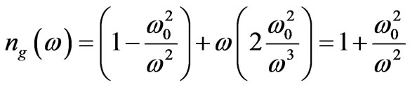
 , gives group refractive index. That is frequency response of NRM behavior, (only to its first derivative term at the frequency
  near electric plasma and magnetic plasma resonance where,
  and
and  for NRM), is defined as group refractive index, which needs be positive.
Meaning that
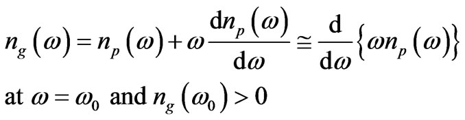 (1)
(1)
This demarcation of phase and group refractive index is very important in understating the behavior of NRM. NRM have unusual properties and in particular Snell’s law predicts that the refracted ray of EM signal on entering such a medium would be refracted on the same side of normal to the surface of the incident beam. The wave number that is  has the opposite sign to its value in positive indexed media, since
  at
at . From (1) we can also write the expression of group velocity as
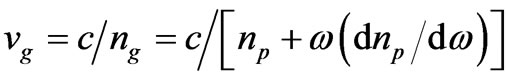 , where the phase velocity is
 ; for a media having dispersion in phase refractive index. It is shown [6,7, 14-17,21-26], that however that Poynting vector,
 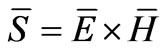 and flow of energy points in opposite direction to the wave vector
 . Hence in the expected direction of the propagation of the EM wave, where the phase travels in opposite direction, is depicted in figure 1(c). The existence of negative values of
  and
and  tends to suggest “negative energy density”; but that is not the case when dispersion is taken into consideration. Indeed NRM can only exist if the NRM media is dispersive. Moreover causality (in form of Kramer-Kronigs relation) requires that group refractive index defined in (1)
 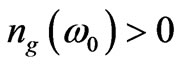 and group velocity
  are always positive [6,7,14-17,21-26].
4. Negative Phase Refractive Index and Positive Group Refractive Index for Negative Refractive Indexed Artificial Media a Prism
In the introduction we have made a statement of our prism experiment showing a negative value of refractive index of –1.8. We clarify that the, observed negative refraction is for “phase-refractive-index” as; 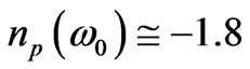 , at
, at , with region of NRM as
  where as the group refractive index
 , as this gives positive group velocity. We thus can say that we can observe a negative phase refractive index but the group refractive index is always shall be positive. Equation (1) should be read at a particular frequency
  of interest, where we are observing a negative refractive index, in our experimental case it were around 33 GHz [6].
We can emulate and model by a simplest model as in (2). An NRM (phase refractive index), by a function such that  is a frequency below which the phase refractive index is negative and above which the phase refractive index is positive. [6,7,14-17,21-26], as (2)
 (2)
(2)
This (2) is simplest form of model where one gets ENG (Epsilon Negative) and MNG (Mu Negative) material representation as  and
and  . Where
  and
and  are respectively electric and magnetic frequencies below which the permittivity and permeability are respectively negative. In (2)
  is chosen in the region where
  and
and  both are negative so that
 . This is design issue dealt in [6,7,14-17,21-26], to realize artificially NRM.
From (2) the differentiation with respect to  gives
gives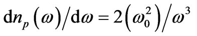 , putting this and (2) in (1) we get
 (3)
(3)
We call  and
and  explicitly to distinguish NRM, for ENG and MNG with negative permittivity and negative permeability, respectively. For plasmonic system to achieve NRM we need
  and
and , and for ideal case for
 , we need
  and
and , [6,7,21-26]. Well one can have electric plasma and magnetic plasma frequency overlapped, as
  below which the values of
  and
and  are negatives, so we get NRM as (2). At the Surface Plasmon Polariton resonance frequency
 , the value of
 , [6,7,18,19,20]; thereby, giving the value of phase refractive index as,
 . Also from (2) we find that
 , when
 . Putting this value of frequency, we obtain that
  when
when  at the frequency of operation Surface Mode Resonances [6,7,18-20]. Thus we say that the phase refractive index is negative for NRM and the group refractive index in positive for NRM.
5. Understanding the Physical Meaning of c2 That Equivalent to Product of Phase Velocity and Group Velocity
If a space between radiator and receiver is filled by vacuum that carrying between them is an electromagnetic radiation with energy E and to that we assign a linear momentum as , is also accompanying by a mass
 . Really radiator after emitting wavepacket recoils with velocity
 , where
  is the mass of radiator. The Wave packet reaches receiver sitting at distance Z after time
 , and the radiator moves a distance
  .
.
The requirement of stillness of inertia of entire system gives moment balance as . This description could be interpreted as, when energy E is transported from radiator to a receiver the mass of radiator gets decreased, but the mass of receiver gets increased by
  equal to
 ! The question is for the multiplier as
  , which is numerically equal to square of velocity of light in vacuum, which is used to justify the dimensions of the Energy Mass equation that is
 ! Well can this multiplier have different physical meaning?
Let us associate  as group velocity of the wave-packet, then in above paragraph the expression for time will be
 . Let the phase velocity be associated to crest and trough be identified as wave-velocity as
  then wave momentum correlation will be
 , this makes the accompanying mass as
 . In free space vacuum, both velocities are
 .
.
This validates our choice of multiplier , and this could be physical interpretation also. In the free space we have
  and thus in free space case
 , that is exactly equal. In media where
  and
and  are different then
  we replace by the product
  not essentially equal to
 . In general the product of group velocity and phase velocity is equivalent (but not always equal to) the
  term.
term.
6. A Special Case of Propagation of Radiation inside Wave Guide Where c2 Is Equal to vpvg
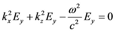
This section demonstrate that the concepts developed in section 5 has special case apart from free space radiation propagation where . In wave guide Electric Field
  must agree with all Maxwell’s equations in the free space inside the guide. Along with divergence of
  must be zero in the free space inside the guide since there are no charges there. That is the same thing as saying that it must satisfy the wave equation (4) [19]
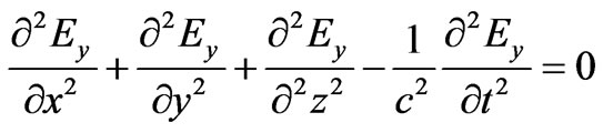 (4)
(4)
The wave guide of our example guides the waves in  direction with
  plane as its cross section having
  dimension (
 ) shorter than
  dimension (a -cm). Our electric field
  has only a
  component, and it doesn’t change with
 . This gives principal propagating mode with
  as
as  . Equation (4), where
  doesn’t depend on
  says that
 (5)
(5)
Unless  is zero everywhere (which is not very interesting) this (5) is correct if
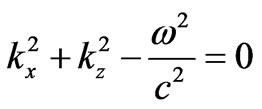 (6)
(6)
We have already fixed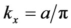 , as for principal mode, so the (6) tells us that there can be waves of type of principal mode (as we have assumed) if
  is related to the frequency
  so that (6) gets satisfied. In other words if
 (7)
(7)
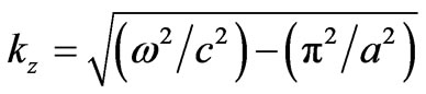
The waves we assumed and described in the wave-guide are propagated in  direction with value of wave number
  given by (7). This wave number from (7) tells us, for a given frequency
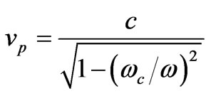
  the speed with which nodes (or antinodes) of waves propagate down the guide, thus giving phase velocity
 . The cut-off frequency of wave guide is
  below which waves do not propagate down the guide [27]. Using these and (7) we get
 (8)
(8)
For frequencies above cut-off where travelling waves exists the  in wave guide is greater than the speed of light in vacuum
 . Therefore, the wave guide simulates a material with refractive index less than unity. In order to know how fast the signals travel, we have to calculate the speed of pulses or modulations made by the interference of waves of one frequency with one or more waves of slightly different frequencies. The speed of the envelope of such group of waves is the group velocity, it is
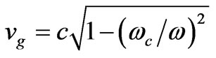
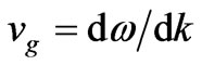 . Taking derivative of (7) and utilizing the definitions of cut-off frequency we get
 (9)
(9)
This is less than the speed of light in vacuum y.
Therefore geometric mean of  and
and  in this special case is just equal to c.
7. Relation vpvg = c2 Similarity with Quantum Mechanics
The Section 5 and Section 6 give us curiosity a similar relation in quantum mechanics. For a particle with any velocity (even relativistic) the momentum  and energy
  are related by
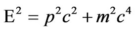 (10)
(10)
But in the quantum mechanics the energy is  and the momentum is
 , that is
  so we write (10) as
 (11)
(11)
 (12)
(12)
which looks very similar to (7), an interesting observation. The equation (10) has two parts a corpuscular part represented by  and the wave-energy momentum part represented by
 . These two components are represented by right angle triangle of figure 4. So we get total energy as (10) that is
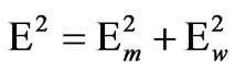 . In the next sections we shall use this relation and see how, equivalence of
  that is product of
  and
and , is utilized see have energy and momentum transport.
8. Energy and Momentum Transfer to Media by a Photon
Consider photon travelling in free space with mechanical energy 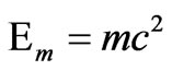 that is energy associated with its corpuscular part, and with phase or wavemomentum as
  having wave energy as
 , thus total energy is
 , having relation as below [27].
 (13)
(13)
We depict this by diagram of figure 4. Call  as phase velocity and
  as group velocity of monochromatic EM signal travelling in the region
 , where the
 , with relative permeability
 , and relative permittivity as
 . Conventionally, we can write for the dispersion less ideal region (
 ) that is;
 (14)
(14)
This we are assuming that  in a vacuum where EM waves are travelling is ideal condition. For negative indexed material NRM (lossless and ideal case, with
 ) we can write, an approximate relation (15), for region (
 ), where we have assumed perfect condition as
 ; with refractive index as
 , and
, and  this enables the propagating modes inside the LHM slab, with (15). In (15) we assume
 , inside LHM, (assumed ideally).
 (15)
(15)
This negative sign in right hand side is represent that group velocity and phase velocity are 180˚ apart from each other, magnitude being c. Energy mass momentum expression for particle at speed of light in relativistic approach is (13), and substituting (14) we get
 (16)
(16)
where E is total energy p is momentum of the particle (wave) which is present inside the meta-material; m is (rest) mass of the particle carrying the energy packet. The rest mass of photon is zero, but we can always associate a mass , for the Electro Magnetic Energy carrying mechanical (corpuscular) energy
 . This mechanical energy is responsible for radiation positive radiation pressure. While the other part of energy we may associate to phase wave-momentum energy due to the wave nature associated with photon-movement or translation of phases “crests” and “trough’s” motion, in the media; call it infinitesimal spatial translations (vacuum or otherwise).
Manipulating (16) we get the following:
 (17)
(17)
The Equation (17) is for free-space, medium with positive phase and group velocity and both equal to . That is
 .
.
Now we use (17), for NRM medium and manipulate as below:
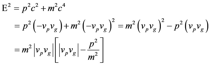 (18)
(18)
Put in the equation (18) , we get
 (19)
(19)
The expression of (19) we split into two parts, the mechanical (corpuscular) energy part  and the energy transport by wave-momentum part
  part. (Figure 5(b))
The (19) shows that particle energy is retained itself by the particle, inside NRM where the phase velocity is opposite to group velocity. In this case no (mechanicalcorpuscular) energy is transferred to the NRM medium. This we derive from the part of rest mass-energy that is the first part of expression ; meaning that corpuscular energy by photon is retained. But the intriguing question is the energy due to wave-momentum part is imaginary negative, inside NRM. That is equal to
  (considering the positive root). We can ascribe to this imaginary “negative’-photon” a wave-momentum a value
  . (Compare figures 5(a) and (b))
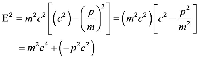
Now we retard the group velocity to , (this is the case with NRM dispersive media with
 ) and have phase reversal with phase velocity inside NRM as
  then
then , and put the same in (16) to get the following
 (20)
(20)
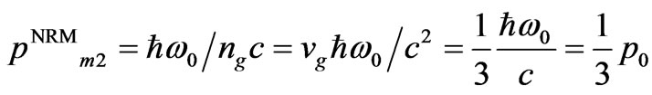
Here the particle inside the NRM has less total corpuscular energy; the difference of energy has been absorbed by the media itself. Expression (20) suggests one third of the corpuscular energy  is retained by the “photon” inside the NRM slab, and the two thirds of its corpuscular energy are given to the slab. The energy due wave momentum of the photon manifests as imaginary negative energy in this case as
 , (again retaining the positive root). We can ascribe to this imaginary “negative’-photon” a wave-momentum a value
 . These concepts are expressed in figure 5(c).
9. Electromagnetic Momentum and Energy Quantization for a Single Photon inside Weakly Dispersive Dielectric Media
The peculiar situation about momentum of electromagnetic radiation is long standing controversy, starting from Mikowski’s (subscripted M) definition [12] (1909) and followed by Abraham’s (subscripted A) definition [13] (1910). Where the former is referred to canonical one and later is referred to mechanical one classically. The traditional electromagnetic momentum density in a medium [12] and [13], with averaging over a time period, are:
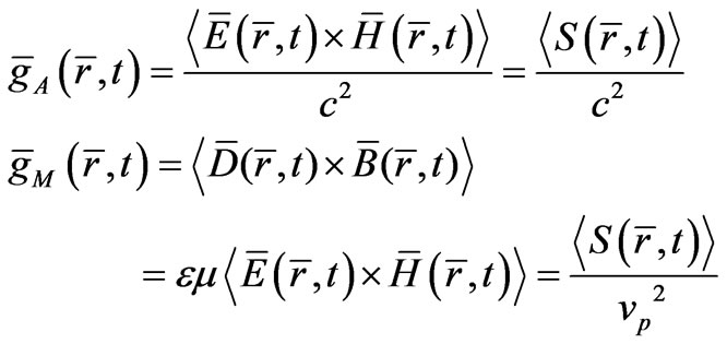 (21)
(21)
In the definition of  above, (21), in dispersive media we have used
 , similar to if it was free space then
 .
.

Figure 5. Energy diagrams of corpuscular and wave (phase) energy in NRM.
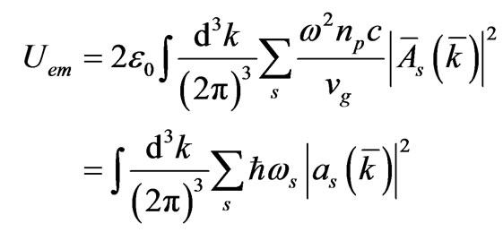
The quantization scheme we will use a very simple one, starts with standard classical expression for the electromagnetic energy density in a dispersive dielectric medium (non-magnetic one to keep the derivation simpler). For classical fields in such a dispersive medium [27], the effective energy is
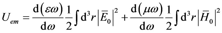 (22)
(22)
For a non magnetic media, then , and from above (22) we obtain, by putting
  (23)
(23)
 (23)
(23)
Note that in (22) (23) we take average over the carrier period , for a monochromatic radiation. Therefore
  is appearing in the expressions, that is average of sinusoidal square. The amplitudes
  and
and  are the peak values of the field. For monochromatic fields of interest, the power Fourier spectrum is concentrated at a particular frequency
  with spectral width
 . The medium is assumed to be weakly dispersive with respect to this wave packet (a single photon), that is
 (24)
(24)
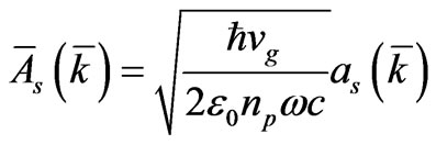
The quantum theory of the electromagnetic field starts by Fourier expanding the vector potential and then substituting operators for the amplitude term. Consider the classical field described by a vector potential in Fourier series having Fourier (root mean squared) amplitude as , that is
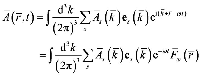 (25)
(25)
The amplitudes in  space are in root mean squared (RMS). The term
  is unit “polarization” vector in a plane perpendicular to
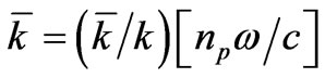 . The
. The  is function of wave vector
  in (25) and
  is mode function satisfying the transversality condition and Helmholtz equation that is
 (26)
(26)
From the vector potential (25) we obtain the electric and magnetic field from 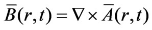 and
and 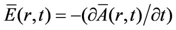 (assuming scalar electric potential is a constant and using
 ), as
), as
 (27)
(27)
 (28)
(28)
From (27) and (28) we get peak value of the field, from RMS expression of Fourier components as
 and
and
 . We substitute this in (23) and write (29).
 (29)
(29)
We employ the identity
 for the mode functionassuming the mode function is normalized such that this integral is unity we simplify (29) to get
 (30)
(30)
Also with this peak values, of  and
and  we can write time averaged magnitude of the Poynting flux as
 .
.
In this expression we manipulated by using
 to get the Poynting flux, and the Fourier expansion as indicated above is for plane wave expansion, thus
  and
and  are orthogonal, we get simplified Poynting or energy flux expression. This expression we will use later for momentum quantization.
We use the relation  and
and
 ,
,  to rewrite (30) after a simple algebraic manipulation as
 (31)
(31)
This electro-magnetic energy is a harmonic oscillator can be expressed as sum of energies  of several radiation oscillators with new amplitudes as
 , that is
 (32)
(32)
So we get by this quantization rule, a standard
 (33)
(33)
The Hamiltonian and the vector fields are represented as
 (34)
(34)
The quantized vector potential for free space would be, where ,
,  , that is photon in free space, is
 . In this section of Fourier expansion we are considering only the positive frequency
 , and writing the Fourier series representation. Applying the quantization rule to the momentum density definitions (21) we get two momentums as
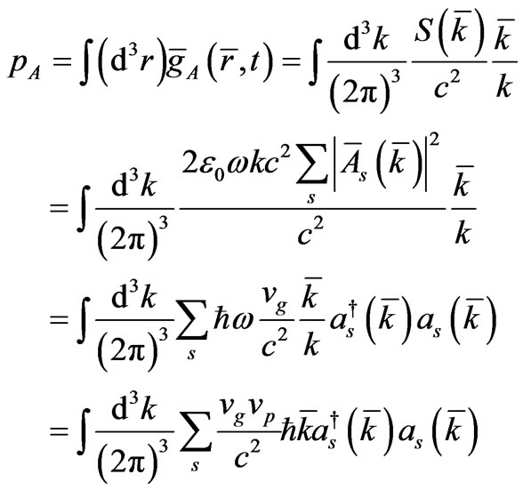 (35)
(35)
 (36)
(36)
The  operation with complex amplitudes represent modal-number operator for photons in the
  -th mode, the expressions (35) and (36) imply that a single photon in a dispersive dielectric medium has the momentums
 (37)
(37)
 (38)
(38)
We will use these definitions and show that these photon momentums are actually mechanical in nature.
10. Pulse of Electromagnetic Energy Travelling in Free Space and Inside Medium Its Transmission and Reflection at the Interface Boundary
The discussion on this section is from classical electrodynamics principles [19]. Let us take following example a pulse of EM energy travelling in free-space at a particular frequency , thus carrying an energy packet of
 . This packet of EM radiation may be represented as a Gaussian pulse; that will strike a medium (other than free-space) located at
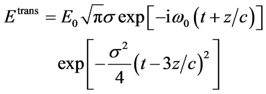
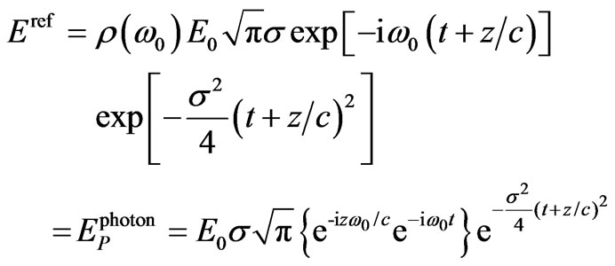
 , by (39), this is derived in (40) [27].
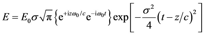 (39)
(39)
The field incident at  is adequately represented by complex Electric field as:
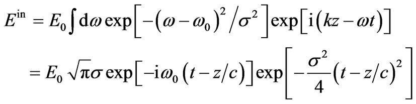 (40)
(40)
The (39) expression is for travelling Electric field that has two parts. The phase part given inside the  brackets, and multiplied by Gaussian travelling envelope in free space as
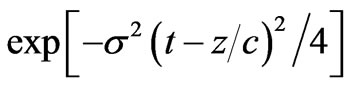 , having variance
 i.e. the width of the packet (Full Width Half Maxima FWHM). The packet is travelling from left to right thus phases (crest and trough are translating in
  -direction) with a phase velocity
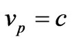 , and the group i.e. the envelope carrying the information/energy is travelling with group velocity
  in the same direction of
  in free space having
 , [19]. Refer figure 1(a) the (39) is depicted there traveling towards right with envelope as dashed and phases as solid lines.
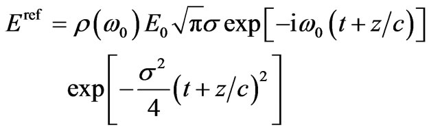
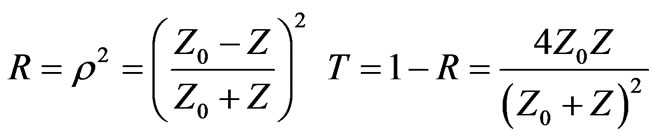
We investigate what happens when this (39) (40) incident Gaussian Electromagnetic pulse enters a medium. This Gaussian pulse is centered at angular frequency  and we assume that this energy beam is weakly focused so we take spatial spread in only one dimension. The reflection and refraction of Electromagnetic waves at an interface are described by Fresnel law. For normal incident [27] we have reflection coefficient
  and transmission coefficient
  described as (41) [27]; both being function of frequency since impedance of media is dispersive.
 (41)
(41)
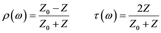
where 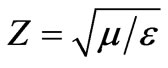 is impedance of medium and
  is free space impedance. Note for a NRM with
  the
the , the incident beam suffers no reflection and is 100% transmitted. The forms of reflected and transmitted waves follow from the spectrum of the incidence pulse (40) as (42) and (43) [27].
 (42)
(42)
 (43)
(43)
It suffices for our purpose to assume that spectrum is narrow so that we can approximate  and
and  by their values at
  and
and  by first two terms of Taylor series expansion (1). This leads to simple Gaussian forms for (42) and (43) as (44) and (45)
 (44)
(44)
 (45)
(45)
For 100% transmission when  say for NRM when
 , with
  and
and  we get
  since
since ,
,  and transmitted field inside NRM is thus given below (46).
 (46)
(46)
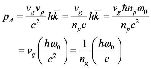
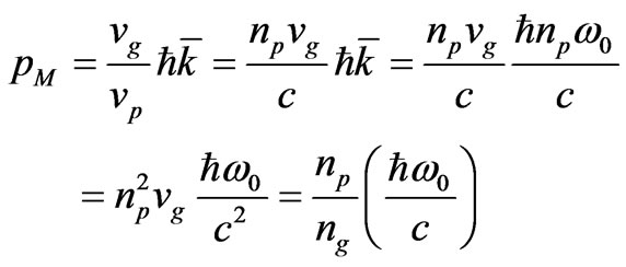
11. Energy Momentum of Gaussian Electromagnetic Pulse
To this Gaussian pulse there is a packet of energy ; we can associate momentum
  with this pulse. The research papers [8-13], discuss momentum of energy of this reversed electrodynamics, in different context but our approach and discussions are differently oriented. Inside a medium we can have scenario where the momentum can have different interpretation if we say
  as phase “wave” momentum inside medium, then if the media has
 , we get confused by this negative momentum indicating a decrease in pressure for radiation of electromagnetic wave, when it strikes a boundary. Call this momentum
  as “wave” momentum, to distinguish from “mechanical” momentum (47) (48) (containing group velocity and group index) as, [12], Minkowski or [13] Abraham;
 (47)
(47)
 (48)
(48)
These definitions of mechanical momentum ensure that they are positive, in side NRM as well. These mechanical momentum definitions (47) (48) give us confidence thought that even with  still there is positive electromagnetic pressure, as against definition of “wave” momentum
 , where we let believe if the electromagnetic pressure be negative in case of NRM. Only for phase reversal we make use of wavemomentum, and for energy transport and electromagnetic energy pressure we shall make use of mechanical momentum. The confusion is arising because of dual nature of radiation, particle as well as wave nature.
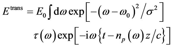
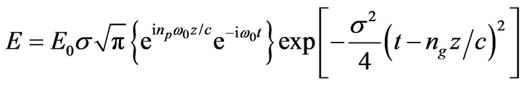
When the Gaussian pulse or this Electromagnetic energy enters a slab with  and
and , assuming 100% transmission into that slab we have different Electric field as from (45)
 (49)
(49)
Now if we state that , and
, and , then we will observe that the Gaussian pulse envelope will compress itself and keep propagating inside NRM block in the same direction of
 ,with group velocity
  but the phases will keep now translating in space in opposite direction but with phase velocity
 , refer figure 1(c). The meeting of the two opposite phases, (refer figure 1(b)) at the NRM boundary gives rise to cusps-owing to surface modes, which travel and oscillate in direction perpendicular to propagation direction and along the surface of the interface [6,7,18-26].
We pose a query that is, if (46) can be called a photon as it has now become inside NRM of our choice as:
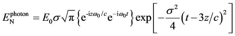 (50)
(50)
is different from original that is
 in the free space.
The (50) seems to suggest that the pulse envelope and the phases travel are in opposite direction, this packet need not be thus called a photon packet rather “negative” photon packet! (Refer figure 1(c)).
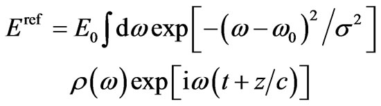
Here we are visualizing that electromagnetic pulse (39) is a “photon”. Our argument of “negative” photon stems from the fact that had there be 100% reflection to (39),  , then we get, a packet of original photon as in (51), from (44) where the envelope and phases are travelling in
  direction after hitting the boundary at
 , thus retaining the character of original photon.

 (51)
(51)
Reflected photon is original photon as incident photon, while transmitted photon inside NRM is “negative” photon (50).
12. Single Photon Momentum Transfer to the Medium
Taking clue from the above discussions in section 8 let us define phase momentum, or wave-momentum of a photon packet as (52); this choice will be clear as we proceed for proof subsequently.
 (52)
(52)
 .
.
If the photon is in free space then (52), would be  or if it were in our chosen NRM with
  and
and , then inside NRM this “negative” photon will have wave-momentum as
  .
.
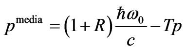
We start our discussion of effect of our single photon entering the medium from region of free space. If the photon is totally reflected then because of the momentum conservation it transfers  momentum to the medium. If the photon passes into the medium in that case momentum will be transferred to the medium at the interface surface where there will be reflection and transmission, the momentum transferred to surface is given as:
 (53)
(53)
where the reflection probability  and transmission probability
  [27] with respect to free-space impedance
  and impedance of medium
  are defined as
 (54)
(54)
The probabilities are square of amplitude and reflection and transmission coefficients (amplitudes) are given by Fresnel relation, as  and
and  used in (54).
Putting (54) in (53) and using  of (53) we get the following algebraic manipulations
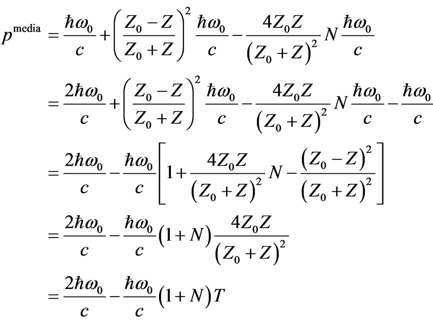 (55)
(55)
Therefore with the definition of wave-momentum as in (53) we get momentum transferred to the media, at the surface as (56)
 (56)
(56)
Using the mechanical momentum definitions of momentum obtained for a single photon in dispersive media in Section 9, and doing the same algebraic manipulations of (55) we get the mechanical momentums transferred to the medium at the surface as:
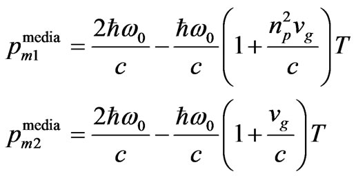 (57)
(57)
All these momentums transferred to medium at the surface of all types (56) and (57) reduces to  for a perfectly reflecting surface when
 , corresponding to change in momentum due to reflection. It is also clear that mechanical momentum transferred to medium by definition of
  will always be positive as
 , however the definition of
 , and
, and  (53), when used the momentum transfer to the medium at surface can be positive or negative depending on the property of media.
Let us take an example of ideal case whence  and
and , zero reflection and 100% transmission for, NRM with
 . The condition for this is
 , gives
 , thus
 . Here the photon passes into NRM with 100% probability (
 ). For this NRM condition the momentum transfer associated with mechanical momentums are identical, corresponding to
 , that is 2/3, of the original photon mechanical momentum transferred to the media. The mechanical momentum retained by photon is (1/3) the original photon momentum. This process is depicted in figure 1, with explanations about momentum and energy in figure 5.
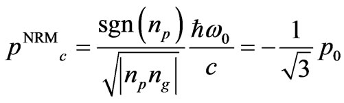
Whereas the wave-momentum transferred (56), for these values is  of the original momentum. The wave-momentum retained by “negative” photon is
  times the original momentum, pointing in opposite direction to wave-momentum of original photon. This also factually matches that inside NRM phase velocity is opposite to the energy flow or group velocity [6,7,18-26]. The mechanism is shown in figure 5(c). The case where
 , (hypothetically if it exists) the wave momentum transferred (56) to the medium is twice the original wave-momentum, and no mechanical momentum gets transferred to the media, well this is case of total internal reflection. For a medium
  and
and , the wave and mechanical momentum transferred to the medium is zero, that is all the momentum is retained by photon.
Let us consider the length of NRM slab, as , with
 , and
, and . The photon is retarded in comparison to its position in absence of medium by distance
 , which is
 (58)
(58)
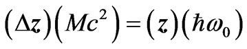
where  is the thickness of medium. The relativistic form of Newton’s first law of motion requires that the centre-of-mass energy of a system not subjected to any external force should be stationary or in uniform motion. Our medium is isolated from such external influence then the relevant total energy is sum of photon energy
  and the rest mass energy of the medium
 , where
  is mass of medium. The fact that photon has been retarded by the medium means the centre-of-massenergy can only have been in uniform motion if the medium has itself moved to the right by a distance
 , then the moments are
 (59)
(59)
Substituting value of  from (58) we get
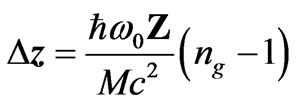 (60)
(60)
This motion can only take place if energy transfer takes place from photon whilst inside the medium. The required velocity of the medium is , from which we can readily obtain momentum
 (61)
(61)
where  is the initial momentum of the photon in free space. Momentum conservation suggests that we ascribe the difference between the initial momentum and this medium momentum to the photon momentum inside the medium. From previous section the mechanical momentum of photon in this NRM would be
 (62)
(62)
 (63)
(63)
The motions of the recoil and momentum transfer to the media, as described here can only take place if the momentum nature be of mechanical. Therefore the obtained definitions of the Minkowski’s and Abraham’s momentums are mechanical in nature; the wave momentum is different from them. The wave momentum and the mechanical momentums of single photon in NRM is calculated in (20); which also corresponds to (62) and (63), refer Figure 5. The wave momentum of photon inside this NRM slab is separate than Minkowski’s, Abraham’s momentum.
 (64)
(64)
The (62) (63) states that; (1/3) of the mechanical momentum is retained by the “photon” inside this NRM. This is well equating as if 1/3 of “particular” photon corpuscular energy is retained by photon inside NRM, whereas the wave-momentum retained by photon inside NRM (64) is  times the original wave momentum-also derived in (20).
13. Imaginary “Reactive Energy” and “Wave-Momentum” inside Medium
In the previous sections we could balance the retardation effect stating that the corpuscular energy that comprising of mechanical photon momentum is transferred to the medium thereby inside NRM the retardation of photon takes place. What was intriguing was imaginary energy of the photon inside the NRM, what we termed as “reactive” energy. This reactive energy of photon inside NRM is making the waves of phases travel backward inside NRM as contrary to positive indexed material. This reactive energy, represented as perpendicular in figure 5, is the translation of space which gives phase and only on which rides the information or packet or lump (figure 3). The active energy is the corpuscular part and the reactive energy is the wave part-both are needed be it positive indexed material negative indexed material or be it free space. The depiction is shown in the figure 5. The difference in NRM is that the reactive energy is opposite to what is in free space or in positive indexed material. This reactive energy of manifests as wave-momentum, giving infinitesimal spatial translations; positive spatial translations in case of free space or positive indexed material and negative spatial translations in case of NRM. On these spatial translation the information, packet, photon travels with group velocity manifesting through mechanical momentum and active energy (the base part in figure 5).
14. Wave Equation for Negative Indexed Material
We can identify the motion of the photon pulse with mechanical momentum but the wave momentum corresponds rather to motion of the phase fronts. The difference is analogous to that between phase and group velocities for a wave; the phase velocity is that at which the phase font propagate, while the pulse and its associated energy propagate at group velocity, thus the phase velocity does not appear in mechanical momentum expressions used above.
We now resort to classical wave as photon and see if we can distinguish between positive refractive indexed media and negative refractive indexed media, through wave equation. Classical Quantum Prescriptor and Schrodinger wave equation, where the total energy of system is expressed as Kinetic plus potential as
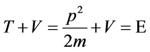 (65)
(65)
By putting standard Q prescriptors that is 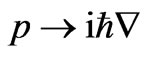 and
and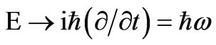 , and in addition asking these prescriptors to operate on wave function
 , the standard Schrodinger wave equation is obtained as
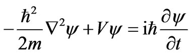 (66)
(66)
The plane wave solution in vector form is
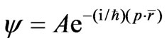 . With
  as photon’s momentum vector linked with its wave vector, and
 , without any potential the wave travels in straight line and we have
  (as
(as ) and we obtain potential free wave equation as
 (67)
(67)
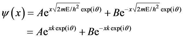
This has two solutions
 (68)
(68)
(68) is case for positive E a propagating case
 (69)
(69)
(69) is case for negative E a bounded case. This bounded case is for surface wave happens for ENG or MNG only.
Let us take the Q prescriptors modified as (70)
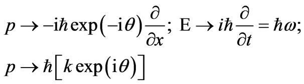 (70)
(70)
Put them in potential free energy expression  , when we operate this on wave function
 , we get a new Schrodinger equation as
 (71)
(71)
the solutions are for this wave equation then:
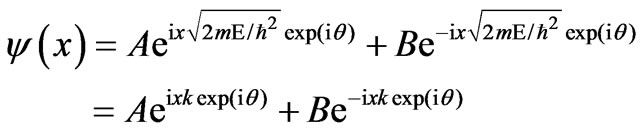 (72)
(72)
(72) is case for propagating case
 (73)
(73)
(73) is case for bounded case.
A quick verification shall state that for  one gets wave equation for normal media where the Right Handed Media (RHM), while
  gives a wave propagation in Left Handed Media (LHM) with NRM. This also opens up a possibility of having a system in between RHM and LHM. This gives a wave description of RHM and LHM where in the later case the phase is opposite the energy flow can be represented as different Quantum prescriptors and different Schrodinger wave equations. At least mathematics hints so; the physical consequences are far from reality, at present for these new Q-prescriptors. The rotational component
  may be personified as demarcation between phase velocity and group velocity and their relation to the phase and group indices, a future work! The future work shall also relate the relation between this rotational component with that of
  in new formulation of the canonical (wave) momentum.
15. Conclusions
Experimental realization of negative index of refraction has as a result raised important questions about the validity of this negative value in well known formulas of physics. The question of corpuscular energy transport inside negative indexed material, formation of reactive (negative-imaginary) energy inside the negative indexed substances, the character of single photon pulse especially its momentum (corpuscular and wave) is addressed along with duality of particle-wave nature of photon. Also it has been shown the classical Minkowski’s and Abraham’s definition for single photon inside negative indexed material is mechanical in nature and is related to corpuscular part of wave-particle duality, which corresponds to active energy, whereas we need separate definition of “wave-momentum” corresponding to wave energy (reactive in nature), for spatial infinitesimal translations in forward or backward direction opposite to energy flow. Few new concepts regarding new wave-momentum inside slab and reactive energy inside negative indexed material, and new generalized wave equation is proposed; to meet the future theoretical advances on these realized negative indexed materials.
16. Acknowledgements
This work is supported fully by Board of Research in Nuclear Science (BRNS) Department of Atomic Energy (DAE): the project is called LEFT HANDED MAXWELL SYSTEMS (LHM-Project). We acknowledge the encouragement received by Sri. B. B. Biswas, Head Reactor Control Division-BARC, Dr. B. N. Jagtap, Head AMP Div. BARC, Sri. G. P. Srivastava Dir. E & I Group BARC, Dr. R. K. Sinha Director BARC, and Dr S. Banerjee Chairman AEC Department of Atomic Energy (DAE); for inspiring us to do counterintuitive science.
The author acknowledges the team for this LHM Project, comprises of Sougata Chaterjee (sougata.sameer@ gmail.com) Research Scientist SAMEER, Amitesh Kumar (amiteshkumarsss@yahoo.co.in) Research Scientist SAMEER, Paulami Sarkar (paulami.sameer@ gmail.com) Scientist-SAMEER, Arijit Mazumder (arijit.majumder@ gmail.com) Scientist SAMEER, Dr. Ananta Lal Das (ald.pdirector@gmail.com) Director SAMEER; Society for Applied Microwave Electronics Engineering & Research (SAMEER) Kolkata. Prof. Subal Kar (subalkar @hotmail.com) Institute of Radio Physics & Electronics (IRPE) University of Calcutta, Kolkata, and Guide/ Consultant for LHM Project.
REFERENCES
- R. W. Ziolkowski and E. Heyman, “Wave Propagation in Media Having Negative Permittivity and Permeability,” Physical Review E, Vol. 64, No. 5, 2001, p. 056625.
- R. Shelby, D. R. Smith and S. Schultz, “Experimental Verification of a Negative Index of Refraction,” Science, Vol. 292, No. 5514, 2001, pp. 77-79. doi:10.1126/science.1058847
- V. Lindell, S. Tretyakov, K. I. Nikoskinen and S. IIvonen, “BW Media with Negative Parameters, Capable of Supporting Backward Waves,” Microwave and Optical Technology Letters, Vol. 31, No. 2, 2001, pp. 129-133. doi:10.1002/mop.1378
- A. Grbic and G. V. Eleftheriades, “Experimental Verification of Backward Wave Radiation from a Negative Refractive Index Meta-Material,” Journal of Applied Physics, Vol. 92, No. 10, 2002, pp. 5930-5935. doi:10.1063/1.1513194
- D. R. Smith, S. Schultz, P. Markos and C. M. Soukoulis, “Determination of Effective Permittivity and Permeability of Meta-Materials from Reflection and Transmission Coefficients,” Physical Review B, Vol. 65, No. 19, 2002, pp. 195104-19109.
- S. Das, “Lectures: Parts 1-8 Left Handed Maxwell Systems,” Class Room Lectures for the Reversed Electrodynamics.
- S. A. Ramakrisna, “Physics of Negative Refractive Indexed Material,” Reports on Progress in Physics, Vol. 68, No. 2, 2005, p. 449. doi:10.1088/0034-4885/68/2/R06
- U. Leonhardt, “Momentum in an Uncertain Light,” Nature, Vol. 444, 2006, pp. 823-824. doi:10.1038/444823a
- R. N. Pfeifer, T. A. Nieminen, N. R. Heckenberg Halina Rubinsztein-Dunlop, “Momentum of an Electromagnetic Wave in Dielectric Media,” Reviews of Modern Physics, Vol. 79, No. 4, 2006, pp. 1197-1216. doi:10.1103/RevModPhys.79.1197
- S. Setiawan, T. G. Mackay and A. Lakhtakia, “A Comparison of Super Radiance and Negative Phase Velocity Phenomena in Ergo Sphere of Rotating Black Hole” Physics Letters A, Vol. 341, No. 1-4, 2005, pp. 15-21. doi:10.1016/j.physleta.2005.04.064
- P. W. Milonni, “Field Quantization and Radiative Processes in Dispersive Di-Electric Media,” Journal of Modern Optics, Vol. 42, No. 10, 1995, pp. 1991-2004.
- H. Minkowski, “Die Graddglaichugen fur die Electromagnetischen Vorgange in bewegten Korpern,” Nachrichten von der Gesellschaft der Wissenschaften zu Göttingen, Mathematisch-Physikalische Klasse, Weidmannsche Buchhandlung, Berlin, 1908, pp. 53-111.
- M. Abraham, “Zur Electrodynamik bewegten Korpern,” Rendiconti del Circolo Matematico, Palermo, 1909, pp. 1-28.
- V. G. Veselago “Electrodynamics of Materials with Negative Index of Refraction,” Physicsâ Uspekhi, Vol. 46, No. 7, 2003, pp. 764-768.
- D. Felbacq and A.Moreau, “Direct Evidence of Negative Refraction at Media with Negative Epsilon and mu,” Journal of Optics: Pure and Applied Optics, Vol. 5, 2003, pp. L9-L11.
- V. G. Veselago, “The Electrodynamics of Substances with Simultaneously Negative Values of ε and μ,” Soviet Physics Uspekhi, Vol. 10, No. 4, 1968, pp. 509-514. doi:10.1070/PU1968v010n04ABEH003699
- V. Veselago, L. Braginsky, V. Shklover and C. Hafner, “Negative Refractive Index Materials,” Journal of Computation and Theoretical Nanoscience, Vol. 3, 2006, pp. 1-30.
- A. Kamli, et al. “Coherent Control of Low Loss Surface Polaritons,” Physical Review Letters, Vol. 101, No. 26, 2008, pp. 263601-263605. doi:10.1103/PhysRevLett.101.263601
- H. Kogelnik, “Theory of Optical-Waveguides in Guided Wave Optoelectronics,” Springer-Verlag, Berlin, 1988, pp. 7-88.
- A. A. Barybin and V. A. Dmitriev, “Modern Electrodynamics and Coupled-Mode Theory: Application to GuidedWave Optics,” Rinton Press, Princeton, 2002.
- J. B. Pendry, J. Holden, W. J. Stewart and I. Youngs, “Extremely Low Frequency Plasmons in Metallic MesoStructures,” Physical Review Letters, Vol. 76, No. 25, 1996, pp. 4773-4776. doi:10.1103/PhysRevLett.76.4773
- J. B. Pendry, J. Holden, D. J. Robbins and W. J. Stewart, “Low Frequency Plasmons in Thin Wire Structures,” Journal of Physics Condensed Matter, Vol. 10, No. 22, 1998, pp. 4785-4808. doi:10.1088/0953-8984/10/22/007
- J. B. Pendry, J. Holden, D. J. Robbins and W. J. Stewart, “Magnetism from Conductors and Enhanced Non Linear Phenomena,” IEEE Transactions on Microwave Theory and Techniques, Vol. 47, No. 11, 1999, pp. 2075-2084. doi:10.1109/22.798002
- D. R. Smith, W. J. Padilla, D. C. Vier, S. C. Nemat Nasser and S. Schultz, “Composite Medium with Simultaneously Negative Permeability and Permittivity,” Physical Review Letters, Vol. 84, No. 18, 2000, pp. 4184-4187. doi:10.1103/PhysRevLett.84.4184
- D. R .Smith and N. Kroll, “Negative Refractive Index in Left Handed Materials,” Physical Review Letters, Vol. 85, No. 14, 2000, pp. 2933-2936. doi:10.1103/PhysRevLett.85.2933
- J. B. Pendry, “Negative Refraction Makes a Perfect Lens,” Physical Review Letters, Vol. 85, No. 18, 2000, pp. 3966-3969. doi:10.1103/PhysRevLett.85.3966
- J. D. Jackson, “Classical Electrodynamics,” 3rd Edition, Willey, New-York, 1999.