Journal of Biomaterials and Nanobiotechnology
Vol.3 No.2A(2012), Article ID:18990,9 pages DOI:10.4236/jbnb.2012.322037
Modern Monitoring Intraocular Pressure Sensing Devices Based on Application Specific Integrated Circuits
![]()
1Group of Research in Control and Diagnostics, ESS Bilbao, Vizcaya, Spain; 2Group of Experimental Ophthalmo-Biology, Department of Cell Biology and Histology, University of the Basque Country UPV/EHU, Vizcaya, Spain.
Email: *elena.vecino@ehu.es
Received January 4th, 2012; revised February 16th, 2012; accepted March 20th, 2012
Keywords: Glaucoma; Intraocular Pressure; Monitoring; Implantable Device; Application-Specific Integrated Circuit
ABSTRACT
Glaucoma is a neurodegenerative condition that is the leading cause of irreversible blindness worldwide. Elevated intraocular pressure (IOP) is the main risk factor for the development and progression of the disease. Methods to lower IOP remain the first line treatments for the condition. Current methods of IOP measurement do not permit temporary noninvasive monitoring 24-hour IOP on a periodic basis. Ongoing research will in time provide a means of developing a device that will enable continuous or temporary monitoring of IOP. At present a device suitable for clinical use is not yet available. This review contains a description of different devices currently in development for measuring IOP: soft contact lens, LC resonant circuits and on-chip sensing devices. All of them use application-specific integrated circuits (ASICS) to process the measured signals and send them to recording devices. Soft contact lens devices are based on an embedded strain gauge, LC circuits vary their resonance frequency depending on the intraocular pressure (IOP) and, finally, on-chip sensing devices include an integrated microelectromechanical sensor (MEMS). MEMS are capacitors whose capacity varies with IOP. These devices allow for an accurate IOP measurement (up to +/– 0.2 mm Hg) with high sampling rates (up to 1 sample/min) and storing 1 week of raw data. All of them operate in an autonomous way and even some of them are energetically independent.
1. Introduction
Glaucoma is the second cause of blindness. It affected to approximately 60 million people worldwide in 2010 and there are predictions of noticeable increases within the next decade [1]. It is a progressive, asymptomatic disease of the optic nerve. In the normal eye, aqueous humor is produced in the ciliary body in the anterior chamber at balanced rate. Intraocular pressure (IOP) is the balance between aqueous humor formation and outflow. It circulates throughout the eye and finally drains through the trabecular meshwork into the Schelm’s canal and the episcleral veins [2].
Failure of the aqueous humor to leave the eye due to the obstruction in the drainage sites result in elevated IOP. There are different reasons: an increase in the epiescleras venous pressure [3] or an increase in trabecular resistance outflow [4]. Elevated IOP is not the only diagnostic factor and many people with high intraocular pressures have normal vision. However, 1 mm Hg increase in IOP increases the risk of getting glaucoma by 10%.
IOP varies widely through the day (ranging from 12 - 21 mm Hg) and it is even pulsated according to its cardiovascular origin. Therefore, two or four measurements obtained periodically during the year are not indicative of patients actual IOP. Current methods of IOP measurement do not permit temporary noninvasive monitoring 24-hour IOP on a periodic basis. Such measurements may be critical in understanding the progression of glaucomatous visual loss, especially in normotensive or lowtension glaucoma. Despite numerous previous attempts at continuous IOP monitoring, a device suitable for clinical use is not yet available. However, devices currently in development for permanent IOP monitoring seem to be nearly ready for human testing.
IOP is known to undergo both random fluctuations as well as variations following a circadian pattern. In humans, IOP is highest at night and lower during the daytime, largely due to changes in body position, although other factors appear to contribute. Ongoing research will in time provide a means of developing a device that will enable continuous monitoring of IOP and should lead to improved management of glaucoma with attendant benefits in reducing glaucoma blindness.Thus, there is a need for cost-effective measurement devices for early management of glaucoma.
Classically, the two most widely employed devices to measure IOP were the Goldmann tonometer and the Tono-Pen, which is a microprocessor-controlled portable version of the Goldman tonometer [5]. Both devices utilise the applanation principle, which is based on the relationship between force, pressure and area.
Although the Goldmann method is considered the standard procedure for measuring IOP, it has a number of disadvantages. For the patient, it is highly invasive and uncomfortable. First, the head of the tonometer must come into direct contact with the cornea. Second, in order to prevent reflexes during measurement, anaesthesia must be applied to the numb eye. A fluorescein strip must also be applied to the eye to detect the applanated state. All these steps require a skilled technician or expertise of the ophthalmologist. And, despite the advanced techniques involved, they do not provide an accurate measure of the patients IOP.
The increasing capabilities of the electronics industry for sensing signal processing, actuating and communication with the environment have been applied to health care for years. One of the most spectacular topics in this field is implantable devices. This industry is not completely new. From battery-powered pacemakers, semiconductor electronics have been used to devise implantable medical devices that save lives and improve patient quality of life.
During the last years, the implant volume and other characteristics have been dramatically improved by orders of magnitude [6]. This way, this technology was transferred into new therapy areas such us the measurement of glucose levels, devices interfacing with the body’s electrical network or breath neuromodulation technologies.
Additionally, smaller devices with better performance increases patient acceptance for therapies targeting prevention and enable less invasive and lower cost procedures. Moreover, the advanced miniaturization allows the using of new form factors and even independent devices that communicate with each other as a part of a Body Area Network.
One of the last cutting-edge working areas for implantable devices is their application to monitor glaucoma intraocular pressure (IOP) [7]. So, the former theoretical idea of an autonomous intraocular implantable device using Application Specific Integrated Circuits (ASICs) is very close to become a reality. This paper is a review consisting of an analysis of the main principles that new devices rely on and some of the more new, advanced and representative devices.
Currently some different ideas for implantable devices are being developed. One of the techniques is the integration of a strain gauge pressure sensor into a soft contact lens [8]. This system was initially wired and then made wireless. These devices produce measurements affected by variability, which has to do with the possible movement of the lens. There are other implantable devices that do not suffer from this problem. They are based on LC resonant systems [9]. This solution produces robust, simple and smaller solutions. Conversely they have limited functionality.
Along the past two years, the work of some research groups in implantable devices has produced an important leap in the technology for continuous IOP monitoring [10,11]. A set of new devices consisting of ASICs and microelectromechanical systems (MEMS) has been published. This new systems provide operation over a much longer monitoring period. Recording and measures are done up to every 5 minutes. For instance, one of them consists of an ASIC fabricated with a 0.13 μm technology, MEMS, antenna and capacitive power array. The MEMS sensor is used to convert pressures into capacitance and is fed into the ASIC for data processing and modulation onto a high-frequency carrier for wireless transmission.
In the present review, we will describe the classical Goldmann based measuring methods (tonometry). Then, the main new methods based on Application Specific Integrated Circuits and their theoretical basis and finally, some of the most representative methods of each category are analysed. This review ends with some concludeing remarks.
2. Classical IOP Measurement Methods
The main different principles developed in the past to measure the IOP are: palpation, manometry and tonometry.
Palpation: is also known as digital tonometry. It estimates IOP by gently pressing the index finger against the cornea of the closed eye. This method is notoriously unreliable and the oldest one. It is the simplest, cheapest method but also the least accurate method to estimate the IOP [12]. By comparing tactile estimations of IOP to formal pressure measurements, the examiner’s sense of touch can be educated up to a limit. Bowman suggested in 1862 [13] a classification of the examined tension divided into 9 grades (T1 to T3 and –T1 to –T3), which ranges from “extremely low tension” to “maximally raised tension”. This classification was the first method for quantitative estimation of pressure differences.
Manometry: This is an invasive technique that measures IOP in a more accurate way. It is used mainly as a laboratory technique to perform continuous IOP measurements for the evaluation of experimental pharmacological preparations [14]. Ethical rules indicate the using of this method only for eyes undergoing enucleation or intraocular surgery [15].
Tonometry: It is the process of determination of IOP by means of a device called tonometer. This device determines a value for IOP with minimum damage for the patient’s eye. It is based on the Pascal principle. The pressure applied to an enclosed fluid is transmitted undiminished to every part of the fluid, as well as to the walls of the container. So the working principle consists of trying to measure the IOP accessing to the cornea. This is the only ocular structure, which is externally accessible. Depending on the particular physical principle applied (indentation, applanation, contour matching, rebound), we found different types of tonometers. Any device uses one or a combination of these principles.
2.1. Applanation Tonometry
In this case, the IOP is inferred from the force required to flatten a constant area in the cornea (Figure 1). The physical principle is the Imbert-Fick law [16]: “the pressure in a sphere filled with liquid and surrounded by an infinitely thin membrane is measured by the counter pressure which just flattens the membrane”. The parameters of this law are related in the following way:

According to this expression, there are two ways of determining the IOP: measuring the force necessary to flatten a fixed area (fixed-area tonometer) or measuring the area flattened by a fixed force (fixed-force tonometer). This law assumes an infinitely thin, perfectly elastic and flexible cornea. So the thickness and the resistance offered by the cornea when is pressed are sources of error [17].
2.1.1. The Maklakoff Tonometer
This is a fixed-force tonometer and an early example of this method. This device was developed by von Graefe and Maklakoff in the XIX century. Due to direct contact with the eye, anaesthesia must be applied in the eye as eye drops. IOP was significantly underestimated compared to more modern methods. Other example of this type of devices is the Posner tonometer developed in 1965.
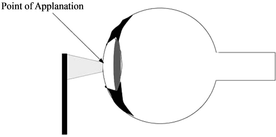
Figure 1. Applanation tonometry.
2.1.2. The Goldmann Tonometer
This is the most widely used tonometer, which is based in the fixed-area principle. The applanation surface has a diameter of 3.06 mm placed in the centre of a plastic cylinder. This cylinder is attached to an arm pushed forward through a spring-loaded knob. The amount of force on the cylinder is precisely controlled and can be read from a scale on the knob. The device is mounted on a slit-lamp biomicroscope. In this case, topical anaesthesia is required together with a fluorescein dye. When this tonometer is employed some variables can affect on the IOP measurements: corneal rigidity can overestimate the IOP; tears can underestimate the measurement and high corneal astigmatism can cause big deviations.
This device is considered to be the gold standard test and the most widely accepted method. However, it is not portable. Perkins tonometer was designed with the same principles but it is a portable one, battery powered and usable in the supine as well as sitting positions. One of the main disadvantages of contact tonometers is the spread of infections if the devices are not adequately sterilized between measurements.
2.2. Dynamic Contour Tonometry
Dynamic contour tonometry (DCT) uses the physical principle of contour matching instead of applanation. The DCT technology is a noninvasive and direct IOP measurement. This technology has been proposed to continuously and accurately measure the IOP of structural characteristics of the cornea and sclera [18].
A practical implementation of DCT tonometry is the PASCAL tonometer. The PASCAL tonometers have a tip that contains a hollow with the same shape as the cornea and a miniature pressure sensor in its centre. In contrast to applanation tonometry, it is designed to avoid deforming the cornea during measurement. Therefore, thought to be less influenced by corneal thickness and other biomechanical properties of the cornea, it is more influenced by corneal curvature. The PASCAL IOP is defined as the diastolic IOP.
2.3. Indentation Tonometry
The basis of this tonometry is: a known force will indent a fluid or gas filled object to a greater degree if the internal pressure is low compared with when the internal pressure is high. Van Graefe, in 1862, was the first that tried to apply this physical principle in a tonometer. In 1905, Schiotz developed the Schiotz tonometer that soon replaced the Maklakoff tonometer. Other indentation tonometers were designed later such as Bailliart tonometer or Maurice Electrical tonometer but only the Schiotz’s is still in clinical use today [19]. The MacKay-Marg tonometer, the TonoPen tonometer and the pneumatonometer device have properties of both applanation and indentation. The original MacKay-Marg tonometer uses a microplunger that protrudes a small amount from a flat footplate of a tubular hand piece. The microplunger is connected to a sensitive transducer, which converts pungler displacement into an electrical signal that is recorded on a paper chart, much like an electrocardiogram [20]. This device has been totally replaced by battery-operated and handheld version, the TonoPen.
In the TonoPen, the tip is covered by a disposable latex cover and applied perpendicularly to gently indent an anesthetized cornea. Each measurement requires several applanations. An acceptable applanation is indicated by an audible click after contact with the cornea. A microprocessor averages several acceptable waveforms and gives a digital readout of IOP on a liquid crystal display, with an estimate of the variability between the component readings. The TonoPen tends to give higher reading than the Goldmann applanation tonometer. Finally, the Pneumatic tonometer allows a continuous IOP reading that is recording on a moving paper chart.
2.4. Rebound Tonometry
Rebound tonometer determines intraocular pressure by bouncing a small plastic tipped metal probe against the cornea. This principle was applied by Obbink by first time in tonometry in 1931. The most recent version is the iCare tonometer. The iCare tonometer was introduced in 1997 [21]. The handheld device uses a projectile of stainless steel. One end is covered with a small plastic cap with a radius of 0.9 mm. Considering all of this, the ideal tonometer would be easy to use, comfortable for the patient and the physician, portable and reliable. A version of this tonometer for the using in small experimental animals has become very popular and one of the most used in research.
3. New IOP Measurement Techniques
There are different possibilities to classify the new IOP measurement techniques. In this paper, a classification depending on the used technology is proposed. There are three main groups: those that are based on soft contact lens, based on LC resonance and on-chip sensing devices. The last two groups produce implantable devices (placed in the anterior chamber) and show some advantages for pressure measurement, as they are independent of ocular surface, cornea rigidity, etc.
3.1. Wireless Contact Lens Sensors Devices
This noninvasive pressure sensing technique is based on a strain gauge embedded in the lens (see Figure 2). This lens is located over the meridional angle of the corneoscleral junction. The sclera is the preferable site for the sensor because of lower sensitivity and less susceptibility to injury than cornea [22].
The strain gauge is able to measure the angular changes at the junction due to variations in IOP. In order to work properly, the lens must be moulded as an exact copy of the eye surface.
The primary designs of this technique used wire lead from the strain gauge [23]. They were passed through the holder and over lower eyelid. These wires were connected to a recording device. However, later refinements of this technique made the recording process wireless, as it is explained later. Leonardi et al. [24], which is a representative design, built a design based on a micro-fabricated strain gauge in Wheastone bridge configuration.
The changes in corneal curvature correlated to intraocular pressure are measured. In general, there is a good correlation between the real pressure and the results obtained from the sensor. The device is placed in the same way as a corrective contact lens, no anaesthesia is required and vision remains unaffected.
The strain gauge mentioned before is inserted in a Wheastone bridge configuration [23], with two sensing resistive gauges (double sensitivity), and two compensation resistive gauges (thermal compensation). Under these conditions, a soft contact lens bends and follows corneal deformations, behaving like a partial spherical shell subjected to a uniform edge moment and has only circumferential strain. The sensing resistive gauges in the device are designed to have a circular arc shape around the centre. They have 11.5 mm of diameter, the same as the average corneoscleral junction position. It is supposed that at this place, the IOP changes cause the maximum corneal deformation.
The sensor contained in the lens is made of a thin microfabricated platinum (170 nm Pt/25 nm Ti). The gauge is embedded between two layers of polyimide, which is suitable for biomedical applications and offers advantages compared to other materials. The sensor is positioned in the mould and the outer shape of the lens is polymerized
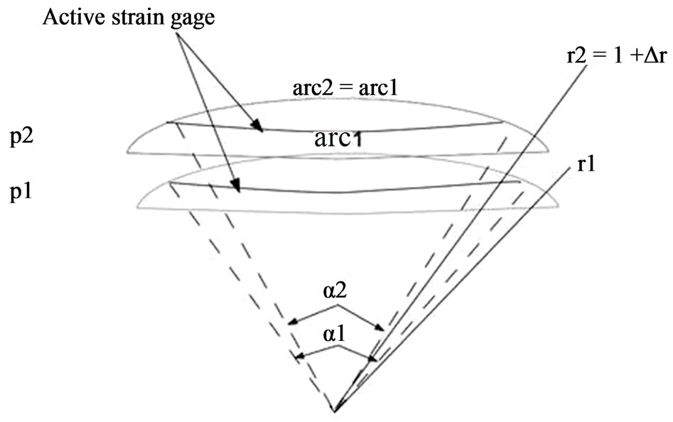
Figure 2. Deformation of a soft contact lens when IOP changes from pressure p1 to p2.
(Figure 3). Then silicone is added and polymerized to form the inner shape.
Initial designs included a 3 cm microflex connection cable, as well as a contact area for a zero insertion force connection [22,23]. However, the using of wires is a major drawback of the system: discomfort for the patient and air bubbles between the eye and the cornea. So, subsequent improvements of these devices resolve the powering and communication between the contact lens and an external recording unit performing it wirelessly by a microprocessor and an antenna integrated into the soft contact lens. In [24], the design of a dedicated application-specific integrated circuit (ASIC) for wireless communication is described. This ASIC has a thickness of 50 μm, it is connected to a sensor and a 10 mm diameter gold antenna was integrated. The final thickness of the lens is about 400 μm at the centre and 100 μm at the border.
The embedded ASIC transmits an output signal Vm proportional to the contact lens strain and therefore the IOP. Data are stored in a portable unit, worn by the patient. The measurement principle is based on stimulating the Wheastone bridge via a DC current I0. The bridge output is a signal voltage Vm proportional to its strain.
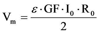
where ε is the strain of the active gages, GF is a gage factor and r the initial resistance of the gages. The lens should follow the corneal deformations, so ε can be written in terms of the initial curvature of the contact lens rand the initial opening angle α. The relation between ε and the variation of the curvature (Δr) is not linear. However, as these variations can be considered very small it is possible to find a simple and linear expression that contains the main idea of this approach: the corneal curvature is related to the IOP and, hence to the obtained voltage Vm.
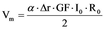
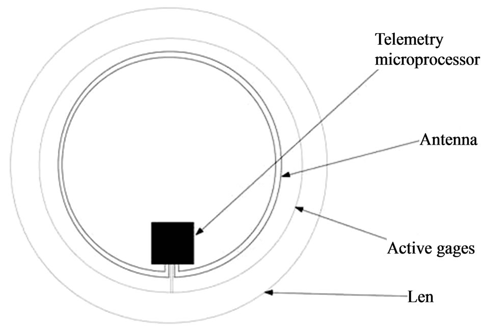
Figure 3. Contact lens wireless sensor.
Finally, the change in the cornea curvature is related to a pressure variation in the following way.
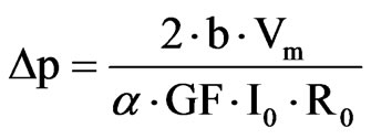
The test bench designed for this device is based on measuring the IOP in enucleated pig eyes with the contact lens sensor. An eye was cannulated with a needle inserted into the anterior chamber and connected with a silicone tube to a column filled with saline, whose amount is controlled by a syringe pump. A pressure sensor in the silicone tube permits the measurement of the pressure real value. The pressure from the contact lens was compared to this one. The contact lens sensor is powered wirelessly by the portable unit through a loop antenna and through the same wireless connection. The obtained data were recorded in a portable unit and sent to a PC.
This CLS showed a high linearity (R2 = 0.9935), a sensitivity of 109 μV/mm Hg and a reproducibility of +/– 0.2 mm Hg. So it is demonstrated that the device would be able to measure a signal equivalent to the human ocular pulsation and follows the IOP in a reproducible way.
3.2. Inductive Couple Telemetry LC Resonance Based Device
Almost all of them use capacitive transducers for pressure sensing [25]. The most common system is a passive LC resonance whose resonance frequency changes with pressure [26-28]. A coil is bonded to the capacitive pressure transducer element. As the capacitive coupling inside the coil changes, the resonance frequency of the whole system changes with pressure. Some devices, must be used to remotely sense the pressure using this technique.
These devices suffer from the requirement of high coupling between the external antenna and implant. So the optimal performance occurs when the sensor and detection circuits can be close to each other.
Traditionally, it was assumed that LC resonant devices were less accurate and with less sensitivity. However, the advances in materials and micromachining have improved the performance of this technique.
In [30] an IOP measuring device based on an inductance-capacitance (LC) resonant circuit is presented. As it was explained before, the capacitor in the LC circuit is used as pressure sensing device. Hence, the capacitance of the sensing device is related to the IOP. When the IOP changes, the capacitance in the circuit is modified and therefore, the resonance frequency also changes. So the measurement principle consists of measuring the resonance frequency of the circuit.
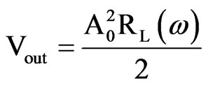
An external coil, placed near the eye, generates a magnetic field whose field lines are perturbed by the sensor. This produce changes in the impedance of the external coil (RL(w)) as a consequence of the variations of the IOP. Then the measure is made by extracting the real part of the impedance of the external coil as a function of the frequency, which depends on the quality factor of the LC circuit itself and the coupling factor between the two coils (this quality factor gives the measurement resolution). Finally, the voltage measure of the external coil gives the impedance and then IOP.
The system is made up of two differentiated parts: the analog section (in charge of the measuring) and a microcontroller. The ASIC microcontroller does not need to be high-speed processing element because the major part of the processing is made in the analog part. The analog/digital conversion and the frequency meter are contained in the microprocessor. The data are stored in a 256 Kilobytes memory. The IOP is recorded at a rate of 1 sample per minute. It is able to store 1 week of raw data that can be uploaded to a personal computer afterwards.
The passive sensor is implanted between the eyeball and the orbital bones where it can be fixed by means of a simple surgical access.
3.3. Capacitive On-Chip Sensor Devices
This is the most modern and technology developed approach. It consists of a programmable intraocular pressure sensor system implant integrated on a single CMOS chip. It contains on-chip micromechanical pressure sensor (MEMS) array, a temperature sensor, an antenna, a capacitive powering array, readout and calibration electronics, a µC-based digital control unit, and an RFtransponder. These devices are more robust for miniature implants and they permit to transmit the power and data to longer distance. On-chip storage of calibration data, high signal-to-noise ratio are other advantages. RF fields are usually used to activate and power sensor chips without using a battery [29]. RF is also used to transmit the data digitally to a remote reader unit. The pressure sensor consists of a pressure dependent capacitor (MEMS) used to convert pressures into capacitance. This information is processed by the ASIC and then, modulated into a highfrequency carrier for wireless transmission [10,11].
These types of sensors improve the possibilities for glaucoma disease treatment. There is a great chance for increasing the devices functionalities. In addition to this, it allows for the measurement for extended periods of time without having the presence of an external device providing power or extracting data.
Measurement principle One of the most representative example of these devices is described in [10,31]. The ASIC is constructed by using a 130 nm technology and is made of four parts: a sensor interface, voltage regulators and references, radio-frequency rectifier for remote powering and a wireless transmitter. An integrated monopole antenna is in charge of the wireless transmission and the independent operation is guaranteed by a capacitor array. That fits within the size constraints of the miniature package to provide power storage and avoid an external power supply.
The measurement of the IOP is based on two capacitors (see Figure 4). On of them is a MEMS, whose capacitance varies depending on the pressure. Therefore, whenever the IOP varies, so does the MEMS capacitance and, hence its charging/discharging time. So measuring the charging time it is possible to derive the IOP value. The other capacitor (Base cap in Figure 4) acts as a reference and its capacitance is equal to the base capacitance of the MEMS.
The MEMS sensor always has an equal or larger capacitance, compared to the reference capacitor, resulting in a longer charge-up time. Digital logic is used to create a pulse transition whenever one of the two capacitors charges up the corresponding Schmitt trigger in Figure 4. The voltage in the MEMS capacitor is:

t is the time while the a current is present, CMEMS is the capacitance of the MEMS sensor and ID is the current supplied to the capacitors. The initial current values are greater to produce a fast charging up to the base capacitance of the sensor. After this, the remaining capacitance, which represents the pressure reading, is charged with a smaller current value. This way, larger time variations are needed for this process and the sensitivity is increased. This effect is crucial as we are considering a low-power, low-delay device. The final time expressions is
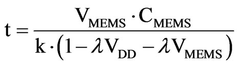

Figure 4. Capacitance-to-time circuit.
VMEMS reaches the threshold of the Schmitt trigger. Then, the output switches from high level to low level. Selecting the value of VMEMS to the threshold in the previous equation it is possible to obtain the time employed to charge the MEMS capacitor. The time between the beginning of the charging up and the threshold is directly proportional to the capacitance of the MEMS and, hence, the IOP. As said before, the reference capacitor reaches the threshold a little bit earlier. This difference represents the MEMS capacitor increment because of the pressure. Therefore, the logic converts this to a pulse, which is further digitized (42.2 KHz) and sent wirelessly or stored in the memory.
To permit the complete independent operation of the device, the system includes a memory storage unit. In this case, a non-volatile memory FeRAM (ferroelectric random-access memory) is used. The wireless data transmission is performed by an antenna (2.4 GHz). This antenna also acts a radio-frequency rectifier for remote powering and recharging. The antenna shape is designed taking into account clinical requirements and electromagnetic optimization (Figure 5). Additionally, to satisfy clinical size requirements, a high-dielectric surfacemount capacitors are used to storage the power drawn from the antenna. The device is able to track the IOP in 5 minutes intervals over 24 hours periods with a 0.5 mm Hg resolution.
The final packaging of this device was designed on purpose using a biocompatible hermetic package made of liquid crystal polymer (low moisture absorption, flexible and thermally bonded without adhesives). Biocompatibility tests for this material can be found at [32,33]. The final product has the form of a tadpole, as shown in Figure 5. The tail contains the antenna (curved along the rim in the anterior chamber) and the head contain the elec-
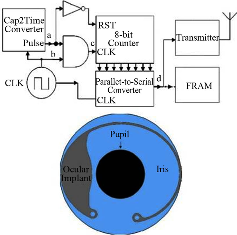
Figure 5. Device block diagram and frontal view of implantation.
tronics. The implantation can be made via a trochanter technique. A complementary receiver to get the stored data was also designed.
Solar energy collecting device.
An interesting possibility is presented in [11], which consists of a device collecting solar energy instead of getting power from an external device. This energy reaches the eye through the cornea, which is transparent, and it is collected by a 0.7 mm2 solar cell. This device is made up of an antenna and an electronics part as previously explained.
The energy collection is based on an integrated solar cell, a thin-film Li battery is also present for energy storage. The measurement principle is also based in a MEM capacitive sensor and an integrated circuit. However, in this case the electronics and the antenna are packaged in a compatible glass housing. The main parts of the integrated circuit are the following: a wireless transceiver, capacitance to digital converter, a microcontroller and a memory. The used fabrication technology is 0.18 mm CMOS.
The IOP is measured every 15 minutes with a pressure resolution of 0.5 mm Hg. The measurement technique is very similar to the previous device. A MEMS capacitor and a fixed capacitor are switched at 50 KHz. The fixed current is compared to the IOP-dependent current. The difference between them is processed to produce the pressure measurement. Again, IOP data are stored, in this case in SRAM memory. The microsystem is capable of storing 3 days of raw data. However, an additional functionality is provided that can compress the data to extend the storage capacity to 1 week.
The user can download the IOP data by using an external device, placed near the eye. The microsystem responds to a wireless query by means of an oscillator acting as a carrier generator and an amplifier. The lifetime is limited to 28 days without energy harvesting. The combination of energy harvesting and low-power operation allows the device to achieve zero net energy operation in low light, requiring 10 hours of indoor or 1.5 of outdoor illumination.
4. Concluding Remarks
This paper reviews the latest different solutions based on application specific circuits for IOP sensing. The main measurement principles used in the different devices have been described: soft contact lens, LC resonant circuits and on-chip capacitive sensor. The last two types generate implantable devices.
Some representative devices of each solution were described. An embedded strain gauge in a soft contact lens permits the accurate measurement by means of an integrated circuit. The sensitivity of this device is +/– 0.2 mm Hg. Wireless operation of these devices has been already devised. The traditional LC resonant circuits have been improved and provide implantable solutions. A device that is able to record 1 sample per minute during 1 week has been presented. Finally, the last cutting-edge devices using a microprocessor with a sensing integrated device have been analyzed. They have an accuracy of 0.5 mm Hg and are able to store big amount of raw data. These devices are able to work wirelessly and independently and have promising improvement possibilities.
These sensing devices are all clear examples of how multidisplinary collaboration between different research fields provides highly promising results. In the future, these devices will be expanded to operate in a closed loop monitoring and treatment system with a great potential for a vast increase in functionality. From a broad perspective, none of these technologies will transform care by themselves, but they can make significant improvements in patients’ treatment. In the future, special attention must be paid to reliability, implantation issues, performance and cost. If all these aspects are managed carefully, exciting possibilities will arise, especially to address chronic disease management needs.
5. Acknowledgements
Ayudas Grupos Consolidados Gobierno Vasco (IT437- 10), ONCE Foundation (Spain), Red Patología Ocular Inst. Carlos III RETICS (RD07/0062).
REFERENCES
- H. A. Quigley and A. T. Broman, “The Number of People with Glaucoma Worldwide in 2010 and 2020,” British Journal of Ophtalmology, Vol. 90, No. 3, 2006, pp. 262- 267. doi:10.1136/bjo.2005.081224
- D. H. Johnson, “Trabecular Meshwork and Uveoscleral Outflow Models,” Journal of Glaucoma, Vol. 14, No. 4, 2005, pp. 308-310. doi:10.1097/01.ijg.0000169397.32674.5e
- T. R. Friberg, G. Sanbor and R. N. Weinreb, “Intraocular and Episcleral Venous Pressure Increase during Inverted Postura,” American Journal of Ophtalmology, Vol. 103, 1987, pp. 523-526.
- N. Weinreb, “Uveoscleral Outflow: The Other Outflow Pathway,” Journal of Glaucoma, Vol. 9, No. 5, 2000, pp. 343-345. doi:10.1097/00061198-200010000-00001
- C. Kniestedt, O. Punjabi, S. Lin and R. L. Stamper, “Tonometry through the Ages,” Survey of Ophtalmology, Vol. 53, No. 6, 2008, pp. 568-591. doi:10.1016/j.survophthal.2008.08.024
- S. Oesterle, P. Gerrish and P. Cong, “New Interfaces to the Body through Implantable Systems Integration,” International Solid-State Circuits Conference, San Francisco, February 2011. doi:10.1109/ISSCC.2011.5746203
- K. C. Katuri, S. Asrani and M. K. Ramasubramanian, “Intraocular Pressure Monitoring Sensors,” IEEE Sensors Journal, Vol. 8, No. 1, 2008, pp. 12-19. doi:10.1109/JSEN.2007.912539
- M. Leonardi, P. Leuenberger, D. Bertrand, A. Bertsch and P. Renaud, “First Steps toward a Noninvasive Intraocular Pressure Monitoring with a Sensing Contact Lens,” Investigative Ophtalmology and Visual Science, Vol. 45, No. 9, 2004, pp. 3113-3117. doi:10.1167/iovs.04-0015
- C. Po-Jui, D. C. Rodger, S. Saati, M. S. Humayun and T. Yu-Chong, “Microfabricated Implantable Parylene-Based Wireless Passive Intraocular Pressure Sensors,” Journal of Microelectromechanic Systems, Vol. 17, 2008, pp. 1342-1351. doi:10.1109/JMEMS.2008.2004945
- E. Y. Chow, A. L. Chebowski and P. Irazoqui, “A Miniature-Implantable RF-Wireless Active Glaucoma Intraocular Pressure Monitor,” IEEE Transactions on Biomedical Circuits and Systems, Vol. 4, No. 6, 2010, pp. 340- 349.
- G. Chen, H. Ghaed, R. Haque, M. Wieckowski, Y. Kim, G. Kim, D. Fick, D. Kim, M. Seok, K. Wise, D. Blaaw and D. Sylvester, “A Cubic-Milimeter Energy Autonomous Wireless Intraocular Pressure Monitor,” International Solid-State Circuits Conference, San Francisco, February 2011. doi:10.1109/ISSCC.2011.5746332
- C. D. Birnbach and M. M. Leen, “Digital Palpation of Intraocular Pressure,” Ophthalmic Surgery Lasers, Vol. 29, No. 9, 1998, pp. 754-757.
- O. Bowman, “On Glaucomatous Affections and Their Treatment by Iridectomy,” British Medical Journal, Vol. 2, 1862, pp. 377-382. doi:10.1136/bmj.2.93.377
- B. A. Ellingsen and W. M. Grant, “Influence of Intraocular Pressure and Trabeculotomy on Aqueous Outflow in Enucleated Monkey Eyes,” Investigative Ophtalmology & Visual Science, Vol. 10, 1971, p. 705.
- M. Blumenthal, M. Chane and I. Ashkenazi, “Direct intraopative continuos monitoring of intraocular pressure,” Ophtalmologic Surgery, Vol. 23, 1992, pp. 132-134.
- H. Goldmann, “Applanation Tonometry,” Transactions Second Glaucoma Conference, Josiah Macy, Jr Foundation, New York, 1957.
- M. M. Whitacre and R. Stein, “Sources of Error with Use of Goldmann-Type Tonometers,” Survey of Ophthalmology, Vol. 38, No. 1, 1993, pp. 1-30. doi:10.1016/0039-6257(93)90053-A
- H. E. Kanngieser, C. Kniestedt and Y. C. Robert, “Dynamic Contour Tonometry: Presentation of a New Tonometer,” Journal of Glaucoma, Vol. 14, No. 5, 2005, pp. 344-350.
- D. R. Anderson and W. M. Grant, “Re-Evaluation of the Schiotz Tonometer Calibration,” Investigative Ophtalmology & Visual Science, Vol. 9, 1970, pp. 430-446.
- E. Marg, “A Report on Mackay-Marg Tonometry in Optometry,” Journal of the American Optometric Association, Vol. 34, No. 12, 1963, pp. 961-965.
- A. Kontiola, “A New Electromechanical Method for Measuring Intraocular Pressure,” Documenta Ophthalmologica, Vol. 93, No. 3, 1997, pp. 265-276. doi:10.1007/BF02569066
- M. Leonardi, P. Leuenberger, D. Bertrand, A. Bertsch and P. Renaud, “First Steps toward Noninvasive Intraocular Pressure Monitoring with a Sensing Contact Lens,” Investigative Ophthalmology & Visual Science, Vol. 45, No. 9, 2004, pp. 3113-3117. doi:10.1167/iovs.04-0015
- M. Leonardi, P. Leuenberg, D. Bertrand, A. Bertsch and P. Renaud, “A Soft Contact Lens with a MEMS Strain Gage Embedded for Intraocular Pressure Monitoring,” 12th International Conference on Solid State Sensors, Actuators and Microsystems, Boston, 8-12 June 2003.
- M. Leonardi, E. Pitchon, A. Bertsch, P. Renaud and A. Mermoud, “Wireless Contact Lens Sensor for Intraocular Pressure Monitoring: Assessment on Enucleated Pig Eyes,” Acta Ophthalmologica, Vol. 87, No. 4, 2009, pp. 433-437. doi:10.1111/j.1755-3768.2008.01404.x
- R. Puers, “Capacitive Sensors: When and How to Use Them,” Sensors and Actuators A, Vol. 37-38, 1993, pp. 93-105. doi:10.1016/0924-4247(93)80019-D
- Y. Backlund, L. Rosengren, B. Hok and B. Svedbergh, “Passive Silicon Transensor Intended for Biomedical, Remote Pressure Monitoring,” Sensor and Actuators A, Vol. 21-23, 1990, pp. 58-61. doi:10.1016/0924-4247(90)85011-R
- K. Van Schuylenbergh and R. Pures, “Passive Telemetry by Harmonics Detection,” Proceedings of 18th Annual International Conference, Vol. 1, Amsterdam, The Nederlands, pp. 299-300.
- O. Akar, T. Akin and K. Najafi, “A Wireless Batch Sealed Absolute Capacitive Pressure Sensor,” Sensors and actuators A, Vol. 95, 2001, pp. 29-38. doi:10.1016/S0924-4247(01)00753-1
- K. Stangel, S. Kolnsberg, D. Hammerschmidt, H. K. Trieu and W. Mokwa, “A Programmable Intraocular CMOS Pressure Sensor System Implant,” IEEE Solid State Journal, Vol. 36, No. 7, 2001, pp. 1094-1100. doi:10.1109/4.933466
- S. Lizon-Martinez, R. Gianetti, J. L. Rodriguez-Marrero and B. Tellini, “Design of a System for Continuous Intraocular Pressure Monitoring,” IEEE Transactions on Instrumentation and Measurement, Vol. 54, No. 4, 2005, pp. 1534-1540. doi:10.1109/TIM.2005.851216
- E. Y. Chow, S. Chakraborty, W. J. Chapbell and P. P. Irazoqui, “Mixed-Signal Integrated Circuits for SelfContained Sub-Cubic Millimetre Biomedical Implants,” International Solid State Circuits Conference, San Francisco, 2010.
- C. Chouard and P. Pialoux, “Biocompatibility of Cochlear Implants,” Bulletin National Academy of Medicine, Vol. 179, 1995, pp. 549-555.
- D. R. Merrill, M. Bikson and J. Jefferys, “Electrical Simulation of Excitable Tissue: Design of Efficacious and Safe Protocols,” Journal of Neuroscience Methods, Vol. 141, 2005, pp. 171-198. doi:10.1016/j.jneumeth.2004.10.020
NOTES
*Corresponding author.