Open Journal of Fluid Dynamics
Vol.4 No.1(2014), Article ID:44154,12 pages DOI:10.4236/ojfd.2014.41008
3D Thermo-Fluid Dynamic Simulations of High-Speed-Extruded Starch Based Products
Alessandro Cubeddu1,2, Cornelia Rauh1,2, Antonio Delgado1
1Institute of Fluid Mechanics, Technical Faculty, University of Erlangen-Nuremberg,
Erlangen, Germany
2Department of Food Biotechnology and Food Process Engineering, Faculty III—Process Science and Engineering, Berlin Institute of Technology, Berlin, Germany
Email: alessandro.cubeddu@tu-berlin.de
Copyright © 2014 by authors and Scientific Research Publishing Inc.
This work is licensed under the Creative Commons Attribution International License (CC BY).
http://creativecommons.org/licenses/by/4.0/


Received 16 February 2014; revised 16 March 2014; accepted 22 March 2014
ABSTRACT
This paper aims to investigate a method to perform non-isothermal flow simulations in a complex geometry for generalised Newtonian fluids. For this purpose, 3D numerical simulations of starch based products are performed. The geometry of a co-rotating twin-screw extruder is considered. Process conditions concern high rotational speed (up to 1800 rpm), different flow rates (30, 40 and 60 kg/h) and water contents (22% and 36%), for a total of 54 simulations. To cope with the geometry complexity a Mesh Superposition Technique (MST) was adopted. The pseudoplastic behaviour of the fluid is taken into account by considering viscosity as function of shear rate (Ostwaldde Waele relationship) and temperature (Arrhenius law). Simulated temperature variations are compared with measurements at same process conditions for validation. Qualitative behaviour of temperature T and shear stress 𝛕 along the screw are analysed and comparisons of different process conditions are presented. By these simulations a database is formed to develop a process control strategy for novel extruder operating points in food technology.
Keywords:High Speed Extrusion; Non-Isothermal Numerical Simulation; Ostwald-De Waele Model

1. Introduction
Since their massive development in the first half of 20th century, extruders have been experiencing a non-stop growth in all industrial fields, not only in plastic industry but also in food processing. The need to develop new products and increase the existent production encourages manufacturers to develop new geometrical screw configurations and to promote research to better understand the complex nature of extrusion processes. Especially in the area of breakfast cereals and convenience food many works have been carried out in order to explain the rheological properties of starch based extrudates. Senouci and Smith [1] as well as Xie et al. [2] characterised shear stress and melt viscosity as function of product temperature, moisture content and melt amylose/ amylopectin content and investigated the regression power law parameters. The influence of the specific mechanical energy (SME) on cornmeal viscosity was illustrated by Chang et al. [3] while product degradation and expansion mechanisms were widely studied in many other works [4] [5] [6] [7] . An exhaustive review of the state of the art about the rheology of starch polymers and related rheometric techniques can be found in [8] . Engineering aspects of extruder performances from an energy point of view have been also investigated [9] [10] and assessment of twin-screw extrusion in producing snack food [11] as well as effects on product characteristics [12] have been experimentally studied. Some of the most important independent variables in the extrusion process are: preconditioning, screw speed N, water content xw, flow rate , barrel temperature TW, die geometry and extruder configuration [13] . All manipulable variables influence in a non-linear way the mechanical and thermal stresses and are responsible for the quality of the final product. Due to the complexity of the extrusion process and high number of design variables, most research has been historically carried out on an experimental basis and only recently, with the growth in computer science, the empirical approach has been supported by numerical contributions. Since the begin of the 1990s theoretical models have been used to simulate the transformation of starchy twin-screw extrudates [14] , but only with the advent of the new millennium first attempts have been done to solve the governing equations of fluid dynamics in 3D twin-screw geometries by means of Finite Element Method (FEM). Ishikawa et al. [15] modelled six discrete angular positions of the screw geometry and performed a non-isothermal quasi-steady-state simulation of a polypropylene material. Avalosse et al. [16] reproduced the results of Ishikawa using a Mesh Superposition Technique (MST). The MST as well as the Mesh Partitioning Technique [17] allows simulating the extrusion process without regenerating the finite element mesh as the screws rotate. Use of MST to perform isothermal fluid dynamic simulations of extruded starch based matrix can be found in [18] .
The present work is intended to provide a method to set non-isothermal flow simulations in a complex geometry for generalised Newtonian fluids. The new contribution is the analysis and discussion of the flow behaviour of the studied extrudate comparing a wide range of process conditions, which cover new and extremely high operating points, up to 1800 rpm. For this aim the MST implemented in the POLYFLOW® software is applied to a twin-screw co-rotating geometry and non-isothermal 3D numerical simulations of starch based products are preformed. The analysis of the extrudate flow behaviour is carried out from a thermal and kinematic point of view for screw speeds ranging from 400 rpm to 1800 rpm. Three different feed rates (30, 40 and 60 kg/h) and two water contents (22% and 36%) are also considered for a total of 54 simulations. The modelled zone is the melt-conveying zone of the extruder, before the die, where the mixture flows as molten monophasic dough. Counter pressure is taken into account. Material parameters were provided by the Department of Food Process Engineering and Department of Applied Mechanics of Karlsruhe Institute of Technology, that performed the experiments and measurements. Validation is made with experimental data for the temperature across the simulated area. Profiles of temperature and shear stress along the simulated area are qualitatively analysed. Quantitative comparisons of all process conditions are also discussed. The performed simulations investigate novel extrusion process conditions in food technology and offer a base of numerical data which can be used to develop a control strategy for optimisation and control of the extrusion process.
2. Materials and Methods
2.1. Geometry and Simulated Area
In Figure 1 the extruder cross section is schematically represented. The modelled area is found at the end of the extruder (melt-conveying zone). The advantages of simulating the flow just before the die are a filling degree of 100%, the possibility to take into account the counter pressure and to compare the calculated temperature variations with the measurements. In fact the temperature transducer plugs are situated across the considered elements. The simulated area consists of three screw elements in a row. Frontal and lateral view with dimensions (in mm) of a single screw and the lateral view of the whole simulated domain are illustrated in Figure 2.
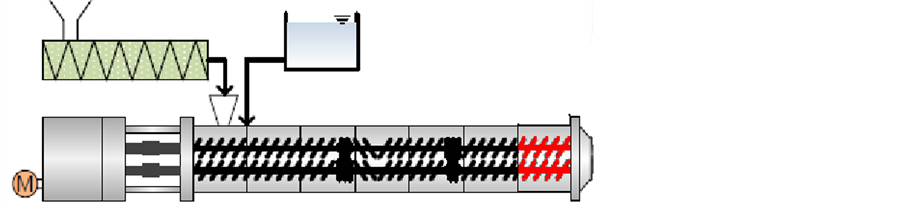
Figure 1. Schematic draw of the extruder and location of the modeled area.
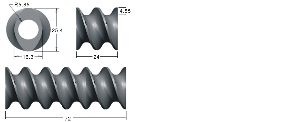
Figure 2. Frontal and lateral view of a single screw element and lateral view of the modeled area (3 elements). Dimensions are in mm.
2.2. Mesh Superposition Technique
Even in a steady state operating condition (i.e. constant screw speed and far away from start-up or shut-down transitories), due to the rotation of the helicoidal screw geometry, the fluid inside the extruder flows at a nonsteady periodic condition. The state variables are time dependent with a periodicity depending on the screw speed. Thus, the discretisation of the fluid domain is in principle also time dependent. In a classical approach [19] the mesh is created only on the volume occupied by the fluid, following the geometrical shape of the screw surface at different angles. As the screws rotate, the mesh must be regenerated to take into account the new relative position between the screw volume and the fluid domain. In this study the use of MST allows avoiding a re-meshing algorithm. The screw meshes and the fluid mesh are independently generated with the mesh generator program ICEM CFD®. The fluid mesh is made up of hexahedra bricks for a total of 25,230 elements. The screws are discretised with tetrahedral, for a total of 21,846 elements. The created meshes are then merged using the tool POLYFUSE, which allows to combine multiple meshes. In the resulting merged mesh some portions of the fluid overlap the screw cells (Figure 3). As the screw rotate new portions of the fluid domain will overlap partially or totally the screws. Making use of the MST requires a modification of the fundamental equations of fluid dynamics.
For an incompressible fluid, mass (Equation (1)), momentum (Equation (2)) and energy (Equation (3)) conservation equations can be written as follows1 [20] :
 (1)
(1)
where  is the velocity,
  is the relative compression factor, artificially added to guarantee the mass
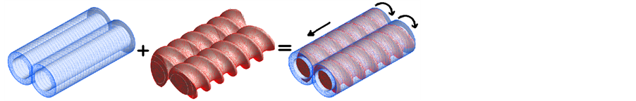
Figure 3. Domain discretisation and mesh superposition.
conservation and avoid peaks of pressure near to the moving elements,  is the shear viscosity and
  the pressure.
 (2)
(2)
where is a step function introduced to distinguish if a fluid mesh node is inside or outside the screw subdomain. If H = 0 then the node is considered part of the fluid, else it is considered to be inside of the moving parts and takes all physical properties of the screws. The parameter
  is the fluid density,
  is shear stress tensor and
  is the acceleration of volume forces,
 (3)
(3)
where  is the specific heat capacity,
  is the temperature and
  is the thermal conductivity.
  is the substantial derivative.
2.3. Kinematic and Thermal Boundary Conditions
The kinematic and thermal boundary conditions are shown in Figure 4. Rotation of the screws and main flow direction are indicated by the arrows. Flow rate  is imposed at the inlet domain. Simulations at 30, 40 and 60 kg/h have been performed. The chosen values of flow rate guarantee a filling degree of 100% in the considered area. Temperature at the inlet is in principle different for each process condition. Indeed, the inlet temperature decreases with the increase in water content and screw speed. However, for simplicity, we used two constant values of the inlet temperature: 418 K for all simulations at
  and 373 K for all simulations at
 . These values are experimental averages for each of the considered water contents, respectively.
On the outlet of the domain a counter pressure is imposed. The values of the counter pressure have been measured at the Karlsruhe Institute of Technology for each considered operating point. The screws are insulated solids which rotate at constant angular velocity. Screw speed varies from 400 rpm to 1800 rpm. A non-slip condition is imposed on the screw surface. On the barrel, there is a non-slip condition and a constant temperature of 373 K. The Newton´s law of cooling has been used on the boundary layer of the internal barrel surface in order to take into account convective effects:
 (4)
(4)
where r is the radial direction and  is the heat transfer coefficient. Common value of
  for starch based products is 500 W/(m2·K) [21] .
2.4. Material Parameters
The fluid is a non-Newtonian shear thinning fluid. It means that the higher the shear rate is, the smaller is the viscosity. A pure viscous model can be written as:
 (5)
(5)
where  is the shear rate. The model used in this study is the Ostwald-de Waele relationship:
 (6)
(6)
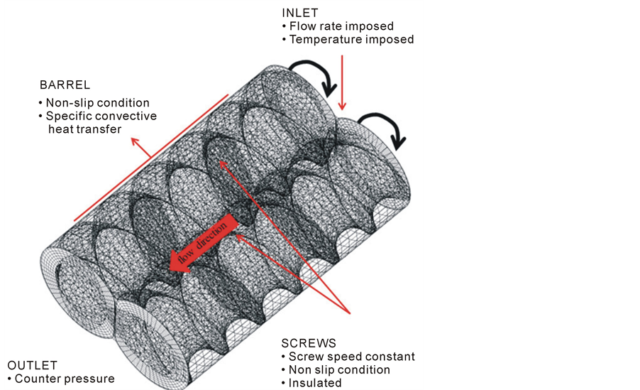
Figure 4. Kinematic and thermal boundary conditions.
where  is the Arrhenius law and n is the flow index, representing the slope of the viscosity curve in a ln-ln diagram. It takes a value <1 in case of a shear thinning fluid like the one considered in this study. The Arrhenius law can be written as follows:
 (7)
(7)
where  is the consistency related to the magnitude of the average viscosity. It represents the apparent viscosity at unit shear rate. The parameter α is the ratio of the activation energy to the universal gas constant. In this case α takes the value of 2407 K, as the measured average activation energy is 20 kJ/mol. The complete equation for the viscosity can be written as follows:
 (8)
(8)
The flow function  is univocal for each process condition. The values of the consistency
  and flow index
  depend strongly on the process conditions. In general
  decreases when screw speed
  or water content
  are increased, whereas
  has the opposite behaviour.
The fluid density  is constant during the extrusion process and takes the value of 1351 kg/m3 for
  and 1288 kg/m3 for
 .
.
Inertial terms and acceleration of gravity have been neglected: the inertial terms because the Reynolds number is less than one, due to the high fluid viscosity and small dimensions of the extruder section, and the acceleration of gravity because it does not play a relevant role in the extrusion process which takes place in a horizontal plane.
The thermal conductivity of the fluid k is considered constant with a value of 0.6 W/(m·K) [22] . The fluid specific heat capacity  has a constant value of 2300 J/(kg·K) [23] .
2.5. Numerical Solution
Due to the high number of finite volumes and the complexity of the numerical problem, the matrices of the coefficients are very large sparse matrices whose factorisation requires high computational resources. For that reason a domain parallelisation was adopted, in order to reduce the computational load on the CPU. Therefore a mesh decomposition was made by using the Chaco decomposition method. A number of 512 sub-parts was specified to partition the whole domain in smaller and simpler to handle sub-domains. The resulting sub-matrices are then solved and reassembled on a parallel basis making use of a High Performance Computing (HPC) technology. To take advantage of the HPC parallelisation capabilities, a multifrontal method [24] has been adopted as solver. To avoid convergence problems due to the dependence of the viscosity on both shear rate and temperature, two simulations for each process condition were performed. In the first simulation only the viscosity dependence on shear rate is considered, while . Momentum and energy equations are hence decoupled. In the second simulation the results of the first simulation are used as initial conditions and only the viscosity dependence on temperature is taken into account. In this case momentum and energy are coupled and therefore an iterative one-way coupled solution is adopted. The one-way method ensures convergence of the solution even if at a convergence rate generally lower than a full coupled method. Convergence difficulties can be caused also by the high value of Péclet number. It is defined as the ratio of the advection heat transfer to the conduction heat transfer:
 (9)
(9)
where d is a characteristic dimension of the geometry (in this case the depth of the channel,  mm) and v is the modulus of the flow velocity. In polymer extrusion the advection heat transfer term is much higher than the conduction heat transfer. The Péclet number is of the order of 103 to 105 [25] . In this study it varies from 3 × 10³ to 3 × 10⁴, depending on the process conditions. A high Péclet number means high non-linearity of the energy equation and causes instability of the numerical solution. To solve this problem the Péclet number was varied iteratively during the second step simulation from a very small value
  to its actual value. Another dimensionless number common in extrusion science is the Brinkman number. It is defined as the ratio of viscous heat dissipation to heat conduction transfer through the barrel:
 (10)
(10)
where Tref is a reference temperature, e.g. the bulk temperature of the fluid. High values of Brinkman number are very common in the extrusion process, due to the high viscosity dissipation. This is a cause of numerical instability. In this study, the Brinkman number ranges from 10 to 30 and therefore also for this number an iterative evolution (from a very small value to its actual value) was adopted.
3. Results and Discussion
In Table 1 are summarised the Ostwald-de Waele parameters A and n of 8 numerical simulations used to validate the temperature field. A constant flow rate of 40 kg/h has been used. Of the 8 validation points, the first 4 are referred to a fluid with 22% of water content and the remaining 4 points to a fluid with 36% of water content. The comparison between measured  and simulated
  across the modelled domain are diagrammed in Figure 5. Simulation results show a good agreement with the measured values for both considered water contents. The source of error is due to the simplifications adopted in the simulations. For instance, the inlet temperature is considered function of the only water content because this variable influences considerably the temperature at the inlet. The influence of the screw speed on the inlet temperature is neglected. Furthermore, thermal parameters like specific heat capacity, thermal conductivity and convective heat transfer coefficient are kept constant, for simplicity. However, the simulations can reproduce accurately the temperature variation trend, demonstrating the suitability of the Ostwald-de Waele model to reproduce the extrudate temperature.
3.1. State Variables along the Screw
It is interesting to focus the attention on one simulation ( rpm,
rpm,  ,
,  kg/h) and have a look at the qualitative variation of the temperature and shear stress in the simulated area. In Figure 6 it is represented the temperature contour over two revolution surfaces located at 11 mm of radius from the rotational axes and over the plane of symmetry of the extruder. The screws rotate anticlockwise and the fluid is pumped in z-direction. The temperature contour shows an increasing in temperature in z-direction from the

Table 1. Ostwald-de Waele parameters A and n used to validate the model.

Figure 5. Comparison between simulated and measured values of temperature.

Figure 6. Temperature contour in the simulated area.
initial value of 373 K to its final value at the outlet of the domain. The viscous dissipation is the cause of the temperature increase. As the temperature increases, the viscosity decreases (shear thinning behaviour) resulting in a reduction of viscous dissipation and then in a lower increase of the temperature. The equilibrium is reached when the viscous heating is balanced by the heat flux through the barrel. The dissipative effects are homogeneously distributed and the temperature profile shows an almost linear increasing trend along the screw (Figure 7). The shear stress contour is represented in Figure 8. Highest values of shear stress are found in the intermeshing zone (between the two screws) and especially close to the barrel. Here the stresses
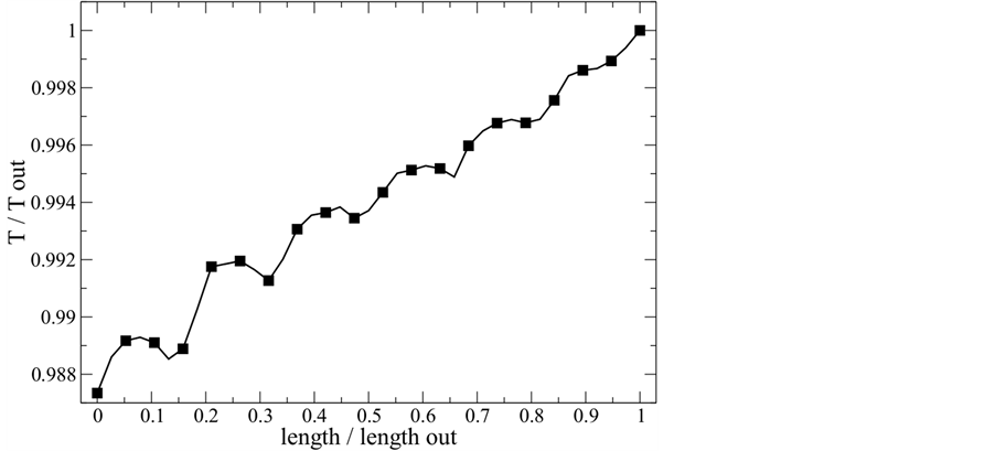
Figure 7. Normalised temperature variation along the screw.
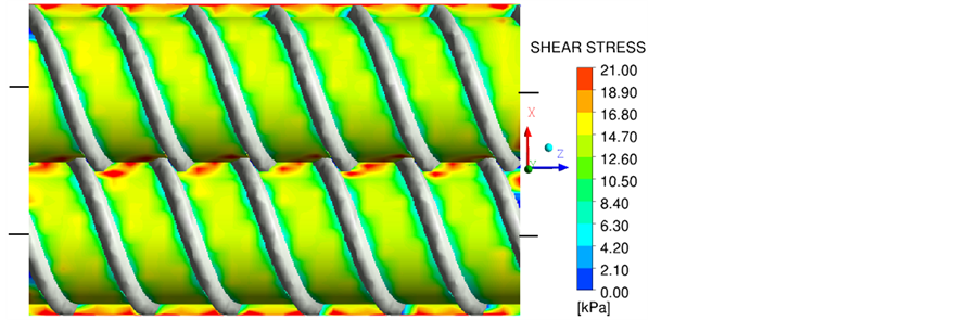
Figure 8. Shear stress contour in the simulated area.
concentrate because of the high relative speed between screws (intermeshing zone) and between screws and barrel (close to the barrel wall). In z-direction the shear stress presents a periodic behaviour. This can be seen in Figure 9 that shows the normalised shear stress variation in a line parallel to the rotation axes. In the middle of each channel where the velocity gradient is higher, the shear stress has a higher value in comparison with its value near to the flights.
3.2. Comparison of Different Process Conditions
The fluid dynamic variables  and average shear stress in the simulated area in function of screw speed are diagrammed in figures 10 to 13. Figure 10 and Figure 11 show a comparison of the temperature variations for the three flow rates considered in this study, i.e. 30, 40 and 60 kg/h. The water content of the dough is 22% and 36% for Figure 10 and Figure 11, respectively. For all curves there is an increase of
  with the screw speed. This is due to the higher mechanical energy transferred to the fluid at higher screw speed. The curves show in general a reduction of the
  while the flow rate is increasing. In fact, the higher the flow rate is, the lower is the permanence time of the dough inside the pumping area and then the temperature increase. Comparing Figure 10 with Figure 11, it is to be noted that, fixing the other process conditions, the temperature increase is smaller for dough with higher percentage of water content in comparison with a fluid with a lower water content. This is the consequence of the smaller average viscosity of a fluid with higher water content and therefore a minor viscous dissipation. The curve at 60 kg/h shows a smaller slope in respect to the curves at lower flow rates. It may be caused from the fact that a high reduction of the permanence time of the dough inside the pumping area makes the fluid less sensitive to the other process conditions.
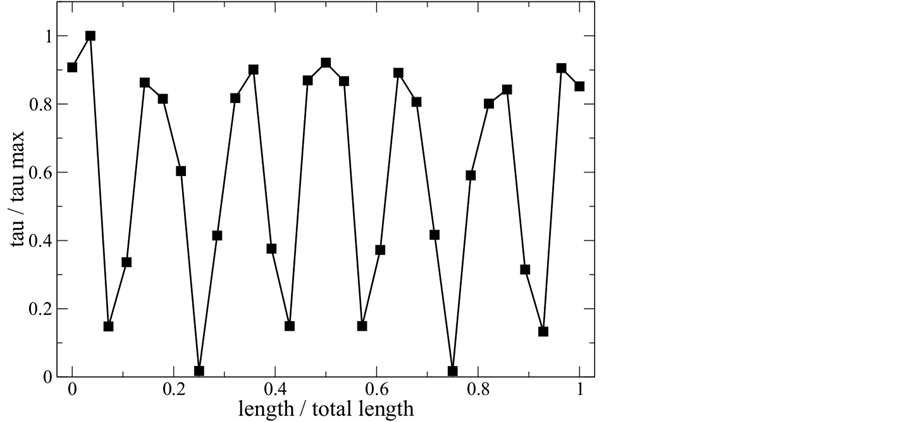
Figure 9. Normalised shear stress along the screw.

Figure 10. ΔT in function of screw speed for three different flow rates. Water content is 22%.
Therefore an increase in screw speed results in a smaller percentage of temperature increase, which causes a flattening of the curve.
In Figure 12 and Figure 13 the average shear stresses at different process conditions are compared for an extrudate with 22% and 36% of water content respectively. In case of a dough with medium water content (Figure 12), the shear stress decreases while the screw speed is increasing, whereas in case of a dough with high water content (Figure 13) the shear stress increases while the screw speed is increasing. This can be explained with a different behaviour of the viscous fluid at different water contents. Increasing the water content results in fact in a more Newtonian behaviour of the fluid. Therefore, the effects of mechanical stress on the fluid, caused by the increasing in screw speed, overtakes the effects of the viscosity reduction due to the shear thinning nature of the fluid. Thus the shear stress increases with the screw speed. At medium and
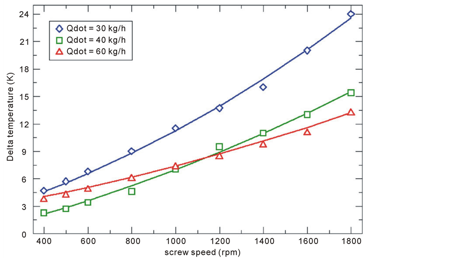
Figure 11. ΔT in function of screw speed for three different flow rates. Water content is 36%.

Figure 12. Average shear stress in function of screw speed for three different flow rates. Water content is 22%.
low water contents the shear thinning behaviour of the polymer is vice versa more relevant and the shear stress reduces while the screw speed is increasing. The influence of the flow rate on the shear stress seems not to be very relevant. The absolute values of shear stresses remain of the order of 50 kPa and 20 kPa for a fluid with 22% and 36% of water content respectively. The higher absolute values for the extrudate with at 22% of water content is due to its higher average viscosity in comparison with a fluid at 36% of water content.

Figure 13. Average shear stress in function of screw speed for three different flow rates. Water content is 36%.
4. Conclusion
3D thermo fluid dynamic simulations of starch based extruded products have been performed. 54 numerical simulations have been carried out for a wide range of process conditions considering novel food properties, different flow rates and very high screw speeds. The fluid has been modelled with the Ostwald-de Waele relationship and the Arrhenius law. The study shows that the chosen viscous model coupled with the temperature dependence of the viscosity is able to describe the behaviour of the studied dough inside the pumping area of an industrial extruder. Temperature variation as well as shear stress is discussed for a fixed operating point in the simulated area and along the pumping direction. Comparison of the simulated variables is also presented for all studied process conditions and interpretations are proposed. Results of the simulations can be used in the industry and for design of a process control strategy which allows to optimise the process of extrusion and to improve the product quality.
Acknowledgements
This research was supported by the German Ministry of Economics and Technology (via AiF) and the FEI (Forschungskreis der Ernährungsindustrie e.V., Bonn) Project AiF 332 ZN. Thanks to the company Coperion GmbH for providing the screw geometry.
References
- Senouci, A. and Smith, A.C. (1988) An Experimental Study of Food Melt Rheology. I. Shear Viscosity Using a Slit Die Viscometer and Capillary Rheometer. Acta Rheologica, 27, 546-554. http://dx.doi.org/10.1007/BF01329355
- Xie, F., Yu, L., Su, B., Liu, P., Wang, J. and Chen, L. (2009) Rheological Properties of Starches with Different Amylose/ Amylopectin Ratios. Journal of Cereal Science, 49, 371-377. http://dx.doi.org/10.1016/j.jcs.2009.01.002
- Chang, Y.K., Martinez-Bustos, F., Park, T.S. and Kokini, J.L. (1999) The Influence of Specific Mechanical Energy on Cornmeal Viscosity Measured by an On-Line System during Twin-Screw Extrusion. Brazilian Journal of Chemical Engineering, 3, 285-295.
- Willet, J.L., Millard, M.M. and Jasberg, B.K. (1997) Extrusion of Waxy Maize Starch: Melt Rheology and Molecular Weight Degradation of Amylopectin. Polymer, 38, 5983-5989. http://dx.doi.org/10.1016/S0032-3861(97)00155-9
- Della Valle, G., Boché, Y., Colonna, P. and Vergnes, B. (1995) The Extrusion Behaviour of Potato Starch. Carbohydrate Polymers, 28, 255-264. http://dx.doi.org/10.1016/0144-8617(95)00111-5
- Della Valle, G., Vergnes, B., Colonna, P. and Patria, A. (1997) Relations between Rheological Properties of Molten Starches and their Expansion Behaviour in Extrusion. Journal of Food Engineering, 31, 277-296. http://dx.doi.org/10.1016/S0260-8774(96)00080-5
- Launay, B. and Lisch, J.M. (1983) Twin-Screw Extrusion Cooking of Starches: Flow Behaviour of Starch Pastes, Expansion and Mechanical Properties of Extrudates. Journal of Food Engineering, 2, 259-280. http://dx.doi.org/10.1016/0260-8774(83)90015-8
- Xie, F., Halley, P.J. and Avérous, L. (2012) Rheology to Understand and Optimize Processibility, Structures and Properties of Starch Polymeric Materials. Progress in Polymer Science, 37, 595-623. http://dx.doi.org/10.1016/j.progpolymsci.2011.07.002
- Janssen, L.P.B.M., Mościcki, L. and Mitrus, M. (2002) Energy Aspects in Food Extrusion-Coocking. International Agrophysics, 16, 191-195.
- Liang, M., Huff, H.E. and Hsieh, F.H. (2001) Evaluating Energy Consumption and Efficiency of a Twin-Screw Extruder. Journal of Food Science, 67, 1803-1807. http://dx.doi.org/10.1111/j.1365-2621.2002.tb08726.x
- Shi, C., Wang, L., Wu, M., Adhikari, B. and Li, L. (2011) Optimization of Twin-Screw Extrusion Process to Produce Okara-Maize Snack Foods Using Response Surface Methodology. Journal of Food Engineering, 7, 1-24.
- Guha, M., Ali, S.Z. and Bhattacharya, S. (1997) Twin-Screw Extrusion of Rice Flour without a Die: Effect of Barrel Temperature and Screw Speed on Extrusion and Extrudate Characteristics. Journal of Food Engineering, 32, 251-267. http://dx.doi.org/10.1016/S0260-8774(97)00028-9
- Hubner, G.R. (2000) Twin-Screw Extruders. In Riaz, M.N., Ed., Extruders in Food Applications, CRC Press, Taylor & Francis Group, Boca Raton, 8-114.
- Della Valle, G., Barrès, C., Plewa, J., Tayeb, J. and Vergnes, B. (1993) Computer Simulation of Starchy Products’ Transformation by Twin-Screw Extrusion. Journal of Food Engineering, 19, 1-31. http://dx.doi.org/10.1016/0260-8774(93)90059-S
- Ishikawa, T., Kihara, S.I. and Funatsu, K. (2000) 3-D Numerical Simulations of Nonisothermal Flow in Co-Rotating Twin Screw Extruders. Polymer Engineering and Science, 40, 357-364. http://dx.doi.org/10.1002/pen.11169
- Avalosse, T., Rubin, Y. and Fondin, L. (2002) Non-Isothermal Modeling of Co-Rotating and Contra-Rotating Twin Screw Extruders. Journal of Reinforced Plastics and Composites, 21, 419-429. http://dx.doi.org/10.1177/0731684402021005442
- Gupta, M. (2008) Non-Isothermal Simulation of the Flow in Co-Rotating and Counter-Roteting Twin-Screw Extruders using Mesh Partitioning Technique. In: ANTEC 2008 Plastics: Annual Technical Conference Proceedings, ANTEC, Milwaukee, 316-320.
- Emin, M.A. and Schuchmann, H.P. (2013) Analysis of the Dispersive Mixing Efficiency in a Twin-Screw Extrusion Processing of Starch Based Matrix. Journal of Food Engineering, 115, 132-143. http://dx.doi.org/10.1016/j.jfoodeng.2012.10.008
- Bravo, V.L., Hrymak, A.N. and Wright, J.D. (2000) Numerical Simulation of Pressure and Velocity Profiles in Kneading Elements of a Co-Rotating Twin Screw Extruder. Polymer Engineering and Science, 40, 525-541. http://dx.doi.org/10.1002/pen.11184
- (2009) Ansys Polyflow 12.1 User’s Guide. http://docsfiles.com/pdf_ansys_polyflow_12_1_user_s_guide.html
- Yacu, W.A. (1985) Modeling of a Twin Screw Co-Rotating Extruder. Journal of Food Engineering, 8, 1-21. http://dx.doi.org/10.1111/j.1745-4530.1985.tb00095.x
- Sakiyama, T., Han, S., Kincal, N.S. and Yano, T. (1993) Intrinsic Thermal Conductivity of Starch: A Model-Independent Determination. Journal of Food Science, 58, 413-415. http://dx.doi.org/10.1111/j.1365-2621.1993.tb04287.x
- Noel, R.T. and Ring, S.G. (1992) A Study of the Heat Capacity of Starch/Water Mixtures. Carbohydrate Research, 227, 203-213. http://dx.doi.org/10.1016/0008-6215(92)85072-8
- Liu, J.W.H. (1992) The Multifrontal Method for Sparse Matrix Solution: Theory and Practice. Society for Industrial and Applied Mathematics, 34, 82-109.
NOTES

1Variables without subscription are referred to the fluid. The subscription el refers to the solid moving elements (screws).