Open Journal of Geology
Vol.3 No.2(2013), Article ID:30375,7 pages DOI:10.4236/ojg.2013.32013
Development of Flash Setting Material for Temporally Pipeline Restoration after Earthquake
Department of Earth Resources Engineering, Kyushu University, Fukuoka, Japan
Email: shimada@mine.kyushu-u.ac.jp
Copyright © 2013 Hideki Shimada et al. This is an open access article distributed under the Creative Commons Attribution License, which permits unrestricted use, distribution, and reproduction in any medium, provided the original work is properly cited.
Received February 8, 2013; revised March 8, 2013; accepted April 8, 2013
Keywords: Flyash; Surfactant; Injection Material; Offshore Structure
ABSTRACT
There are many earthquakes in Japan. If a large earthquake were to occur, it is necessary to consider how pipelines such as: gas, sewage, telecommunications, and so on are restored quickly. At that time, damaged gas pipelines are very dangerous because fire in large areas could be caused by the leakage of gas from the damaged pipeline. Accordingly, it is necessary for gas companies to stop the supply of gas to houses over a large area. Once the gas supply is stopped, there is a considerable amount of time to repair the pipelines over the area. For this reason, a quick method for restoring damaged gas pipelines would be useful after an earthquake. Recently, we have been developing new flash setting material for the damaged gas pipeline by an injection into the house connection of gas when the gas supply is stopped quickly in an emergency. From these points of view, in order to clarify to what degree the contents of flash settling material affect the properties of the injected fly ash mixture causing heavy damage to the gas pipeline in an earthquake, different combinations of fly ash, chemical agents and water were considered in several experiments.
1. Introduction
Japan is the biggest coal importer in the world, importing about 180 million tons, accounting for about 22.8% of the total available coal for trade in the 2007 fiscal year (FY) [1]. Over 100 types of coal every year, with some electric power stations using as many as 20 types of coal per year, are imported. The major sources of Japan’s coal are Australia, Indonesia, China, Russia, Canada and Vietnam. Japan’s dependence on coal is expected to remain at or near the same level in the future.
Considering global environmental issues, efficient and clean utilization of coal is essential to promoting the stable use of coal. In FY2007, about 9.9 million tons of coal ash was produced through coal burning power plants, of which 85% was effectively used and the remainder was disposed of. Of this, 70% was used as cement raw material (alternative for clay), 5% cement/concrete admixture, 10% in public works, 5% in construction, 2% in agriculture, and 6% for other uses [2]. There have been few discussions on increasing the scope of coal ash to be used as cement raw material. Consequently, it is necessary to expand its effective utilization in cement admixture and in public works.
Among the man-made pozzolans, fly ash is probably the most successful component used in mortar injection. When fly ash is added to Portland cement concrete, the same kinds of oxides as those of cement are created. As an injection component, fly ash acts, in part, as a fine aggregate and, in part, as a binding component. However, heavy bleeding and low fluidity can be observed if the cement-fly ash water ratio is high. It is necessary to consider a new pozzolan, which is mixed with fly ash and cement and enhances its durability [3]. In recent years, much trenchless rehabilitation of pipelines has been considered for residents’ and has mitigated the influence on traffic. Although the grouting material is required to make the established pipe and lining material unify, it has high mobility etc. A grouting material using the material that was mixed with the surface-active agent with the fly ash was developed. Usage of fly ash instead of cement leads to improved mobility, reduced construction costs and so on.
There are many earthquakes in Japan. If a large earthquake were to occur, it is necessary to consider how pipelines such as: gas, sewage, telecommunication, and so could be restored immediately. At that time, a damaged gas pipeline is very dangerous because fire over a large area is generally caused by the leakage of gas from the damaged pipeline. Accordingly, a gas company would have to stop the supply of gas to houses over a large area. Once the gas supply is stopped, there is a lot of available time to repair the pipeline. For this reason, a quick method to restore the damaged gas pipeline has to be considered after an earthquake. Recently, we have been developing new flash setting material for the damaged gas pipeline by an injection into the house connection of gas when the gas supply is stopped quickly in a small area in an emergency.
From these points of view, in order to clarify to what degree the contents of flash setting material affects the properties of the injected fly ash mixture into a heavy damaged gas pipeline by an earthquake, different combinations of fly ash, chemical agents and water were considered by means of several experiments.
2. Disaster of Gas Leakage after Earthquake
An earthquake is a sudden shaking of the earth caused by the breaking and shifting of rock beneath the surface. Earthquakes can cause buildings and bridges to collapse, telephone and power lines to fall, and result in fires, explosions and landslides. Earthquakes can also cause huge ocean waves, called tsunamis, which travel long distances across the ocean until they crash into coastal areas.
A fire caused by earthquake damage is a true emergency because the resources to fight fires may be spread out due to a large number of fires, or access to a fire area may be limited or blocked. Furthermore, following an earthquake, fire suppression systems such as: water systems, water sprinklers, and sheetrock siding may be compromised. Many earthquake fires totally destroy the original structure and spread to neighbouring structures [4].
In an earthquake, the shaking of a home or an apartment can cause damage to the gas pipeline and appliances. This damage can result in releases of gas that can lead to fires or even explosions. Structural weaknesses, the absence of appliance anchors, seismic activity, and a lack of flexible pipe connections can all contribute to a greater possibility of gas leaks. This problem is so prevalent that gas contributes to fires after an earthquake [5].
A primary concern when dealing with natural gas leaks and ensuing fires is the protection of property, rather than personal safety, because most homes have several exits that allow for escape from a fire. One of the most common ways of protecting buildings from gas leaks is by installing some sort of shut off valve for the gas supply [6]. For this reason, gas companies should consider how to shut off the gas supply. For a solution to shut off the gas supply, we are developing new material of flash setting by using the mixture of fly ash cement and chemical agents for the damaged gas pipeline by the injection into the house connection of gas when the gas supply is stopped quickly in a small area in an emergency. Figures 1 and 2 show a situation after earthquake. Figure 3 shows a conception of shut off the gas supply.
3. Characteristics of Fly Ash
The wastes generated from coal burning power plants are fly ash, scrubber sludge, ash, spent bed, and fluidized bed wastes. In Japan, these types of wastes are generally called “coal-ash” and classified into two groups: fly ash and clinker-ash [7].
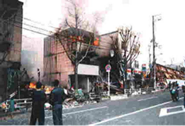
Figure 1. Fire after gas leakage.
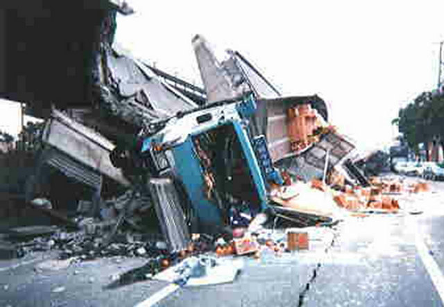
Figure 2. Road damage after earthquake.
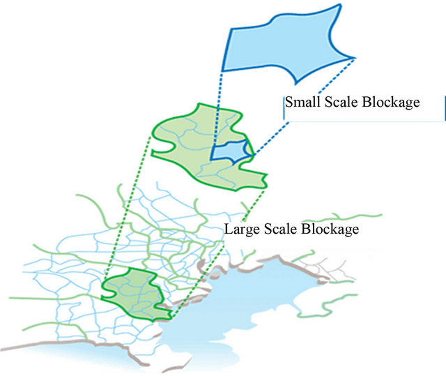
Figure 3. Conception of a shut off for a gas supply.
In Japan, over 150 million tons of coal is imported and about 50 million tons of coal is burned annually for generating electricity. Approximately 15 percent of all the coal burnt is transformed to coal-ash of which 85% to 95% is fly ash and 5% to 15% is clinker-ash. The size of clinker-ash is larger than that of fly ash, and therefore, it is crushed for utilization. About 80% of coal-ash is now utilized and the remains are disposed of at disposal sites. However, the life span of the disposal sites are limited and it is difficult to find new disposal sites. It has therefore been requested that the percentage of utilization of coal-ash be increased in every field in Japan. However, the quality of fly ash, depending on the coal type, restricts the extensive use of fly ash [8].
The predominately spherical particle shape of fly ash provides a smooth flow of the mix by acting as a lubricant that decreases the viscosity of the mix, which reduces wear and tear on the equipment. The particle size range is from less than 0.1, up to 1 mm, but the majority (90%) is less than 0.1 mm. The addition of fly ash also increases the specific surface area per unit weight and produces beneficial effects on segregation and rate of settlement, permeability, bleeding and pozzolanic activity.
Furthermore, the low heat properties of fly ash effectively reduce the temperature of hydration in mixes containing Portland cement by as much as 30%. In Japan, these mixes are called fly ash cement and there are three types of Portland fly ash cement: class A containing 5% to 10% fly ash, class B 10% to 20% and class C 20% to 30%. The mixed cement allows for cost benefits without adversely affecting the long-term strength of the concrete. The chemical composition of the fly ash is shown in Table 1.
4. Requirements of Flash Setting Material for Restoration
As the flash setting material concerns the repair of the gas pipeline, it is necessary that the gel time is small and
Table 1. Main chemical composition of cement and fly ash used in this study.

there are no gaps after the flash setting material is filled. In regards to injection by the flash setting material used by the cement slurry, the volume of space in a damaged pipe is vast because the cement slurry is not filled completely in the damaged pipe due to its bleeding property. In addition, if the ratio of cement and water is increased, it is very difficult to inject it into the space due to high viscosity.
As a result, the injection area is not uniform, even if the injection material is clogged, leakage of gas is exhibited. In addition, as gel times for the marketed flash setting material are 80 - 120 seconds, it is not effective at shutting off the gas supply completely.
The diameter of the house connection pipe from the main pipeline of 100 - 300 mm in diameter is 25 mm. For this reason, if the gel time of the flash setting material is large, the gas supply cannot shut off because the flash setting material after injection into the intersection at the main pipe is spread out. Also, as the small value of the gal time contributes to hardening of the pipe at the house connection, it is impossible to shut off the gas supply. For this reason, the optimum gel time is between 20 and 30 seconds. In addition, low bleeding, high fluidity and high capacity for bearing gas pressure, and so on is needed because the perfect shut off conditions for the gas supply can be satisfied. In order to solve this problem, application of flash setting material, which has sealing properties was attempted.
5. Development of Flash Setting Material
5.1. Experimental Methods
Among the man-made pozzolans, fly ash is probably the most successful component to be used in injection materials. When fly ash is added to the cement, the same kinds of oxides as those existent in the cement are being added. As an injection component, fly ash acts, in part, as a fine aggregate and, in part, as a binding component. Fortunately, there is no substantial alteration in the properties of the original component [9,10].
With this in mind, the requirements of flash setting materials used to shut off the gas supply are as previously mentioned as follows: little bleeding after injection, little separation of the components after injection, sufficient permeability, and a uniform property after injection. With these requirements being considered, a bleeding test, a slump test (Figure 4), a compressive strength test, an adhesive test, a permeability test, and other tests were carried out.
Considering the intended application of the mixture with fly ash and some kinds of agents, those being used on flash setting materials, testing of the viscosity or the fluidity characteristics was carried out by the slump test. The slump test is defined as the Japanese industrial standard. The dimension of the flow cone device was 51 mm × 50 mm. After the mixture was set into the cone on the glass board, the cone was pulled up from the original position. The mixture spread out after pulling the cone up from the original position, the length of the mixture being measured was the flow value. The flow value had good correlation with the yield stress, which is the beginning stress of the flow. Therefore, the larger the flow value, the better the fluidity. Figure 4 shows the device of the slump test.
Figure 5 shows the device of a bleeding test. Fly ash and some kinds of agents are mixed and suspended in water to yield suspension samples of the desired composition and density. The fly ash cement is then poured into a 1000 cm3 laboratory jar and left to rest. At selected intervals, the volume of the sediments suspended in a denser liquid under clear water was recorded. In this experiment, the height of the interface between the clear water and denser suspension liquid indicated the sediment volume. The height of the laboratory jar was 30 cm [11].
Figure 6 shows the illustration of an adhesive test. After injection into the damaged area, the flash setting material has to be kept under gas pressure from the main pipeline. Because of this, an adhesive test was carried out. The dimension of the acrylic pipe was 75 mm × 250 mm. After the mixture was placed into the pipe, pressure was exerted from the top. The adhesive strength was confirmed when the pressure of the mixture was moved after pressurizing at the original location. As the gas pressure
 (a)
(a)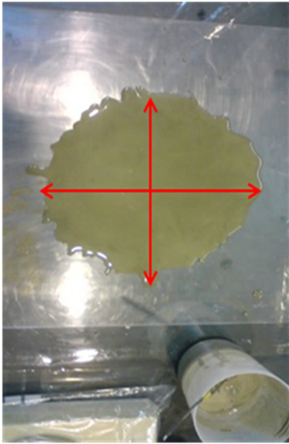 (b)
(b)
Figure 4. Slump test. (a) Device (b) After testing.
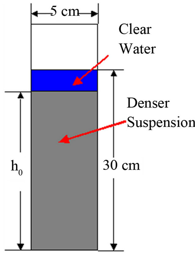
Figure 5. Bleeding test.

Figure 6. Adhesive test.
is set at less than 1.0 MPa in the main pipe, the adhesive strength is set to be more than 1.0 MPa [5].
Furthermore, each component of the flash setting material was sent separately via a pipe from the mixing plant, and the components were mixed just before injection into the damaged area. However, it was not possible to confirm whether or not the flash setting material gelled successfully because it was impossible to check its condition after injection. Therefore, gel time was adopted as a standard check for the filling condition in the damaged pipe. Gel time was defined as the amount of time the flash setting material lost fluidity after its components were mixed. In the case of low gel time, the flash setting material hardens before it is spread uniformly within the damaged area. In the case of high gel time, the flash setting material spread out into the main pipe and it is impossible to shut off the gas supply [12].
5.2. Development of Flash Setting Material
5.2.1. Flash Setting Material
At first, a chemical grouting material is considered as a flash setting material. The chemical grouting material consists of two components: silicic acid sodium as the main component (A agent) and the additional component (B agent) is such a mixture of cement, water, aggregate, and so on [13]. From the results of our previous research, it was clear that the stability of the fly ash mixture increases as the substitute ratio of fly ash for cement increases for bleeding. From this point of view, what degree the contents of flash setting material affects the properties of the injected fly ash mixture by increasing the substitution ratio of fly ash for silicic sand can be called an aggregate. Table 2 lists the contents of the five types of flash setting material. The percentage of the main component is 30% silicic acid sodium and the ratio of the mixture of the main and additional component is 1:1. Table 3 shows the experimental results of the samples the components of which are listed in Table 2.
From the results of the experiments, it is recognized that the gel time decreases when the substitute ratio of fly ash for silicic sand increases. The results of sample No.5 are superior to the other samples; however, it is impossible
Table 2. Contents of three types of flash setting material (unit; g).

Table 3. Gel time, flow value and bleeding ratio of each sample.
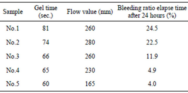
to shut off the gas supply because the bleeding ratio of the sample No.5 is 4.0. Furthermore, the gel time of sample No.5 is not satisfied.
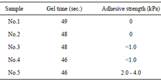
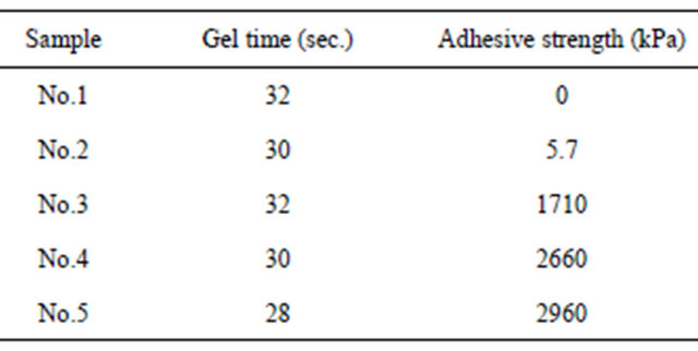
5.2.2. Flash Setting Material Added by Adhesive Agent
In order to satisfy the requirements of flash setting material to shut off the gas pipeline after an earthquake, an adhesive agent is added to sample No.5 in Table 2. This adhesive agent consists of powder emulsion of copolymerization between ethylene and acetic acid vinyl. This adhesive agent is used for the stability of the failure slope or tunneling on spraying against the objectives. Table 4 lists the contents of the five types of flash setting material added by the adhesive agent. Table 5 shows the experimental results of the samples. From the results of adhesive strength, all samples are not satisfied, for example the required gas pressure at 1.0 MPa. The gel times are also larger than the targets which are less than 30 seconds. Furthermore, many voids in all samples are visible curing after mixture of each ingredient. For these reasons, the adhesive agent is not enough for the flash setting material.
5.2.3. Flash Setting Material Added with Adhesive and Swelling Agents
It is understood that the flash setting materials which
Table 4. Contents of five types of flash setting material added with an adhesive agent (unit; g).

Table 5. Gel time and adhesive strength.
were added with only an adhesive agent, are not effective if gas pressure is added. Furthermore, as the gas permeability is very high due to many visible voids in the samples, it is impossible to shut off the gas supply in the main gas pipeline. For this reason, the adhesive and swelling agents were added into the flash setting materials. A swelling agent is selected as the material which controls the shrinking of volume after mixing each ingredient. The swelling agent consists of isolated oxide calcium as the main component and silicic calcium, glass, and so on as additional components. Table 6 lists the contents of the five types of flash setting materials added with adhesive and swelling agents. Table 7 shows the experimental results of the samples.
From the experimental results, sample No.5 is superior to the others. The gel time of No.5 was 28 seconds, and the adhesive strength was about 3.0 MPa. Furthermore, the permeability of water of No.5 was less than about 1.0 × 10⁻⁶ cm/s by the simple permeability test [12].
From the above results, it is possible for flash setting material added by adhesive and swelling agents to shut off the gas supply in heavily damaged areas after an earthquake.
6. Preparation Kit to Shut off the Gas Supply
At present, many Japanese gas companies are taking steps to deal with the situation after large earthquakes as
Table 6. Contents of five types of flash setting material added with adhesive and swelling agents (unit; g).
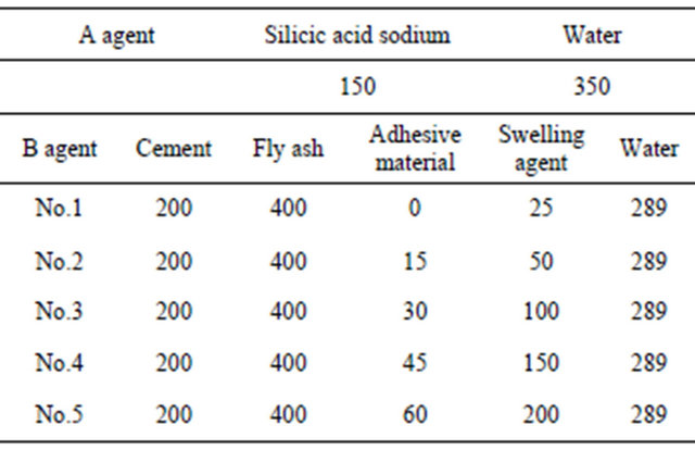
Table 7. Gel time and adhesive strength.
mentioned before. The main pipeline networks are divided into low, middle and high pressure zones. If the main pipeline is damaged, the damaged zones are cut off and separated from the main gas supply. However, if the damaged zones are of a large-scale, the time required for restoration is too much. For this reason, a method for small-scale restoration is needed.
Figures 7 and 8 show an illustration of the preparation kit to shut off the gas supply after an earthquake using flash setting material. The mixing plant is located near the house connection. The A and B agents are injected by the compressor from the mixing plant and mixed both at the valve of the house connection. The average length of the house connection is about 20 m. After the mixture is forced into the house connection by its weight, the material is kept at the joint of the house connection and the main pipe. After complete injection at the joint, the gas supply can be stopped.
7. Conclusions
If a large earthquake were to occur, it is necessary to consider how pipelines such as: gas, sewage, telecommunications and so on are restored immediately. At that time, a damaged gas pipeline would be very dangerous because fires over a large area could occur due to a leakage of gas from the damaged pipeline.
From these points of view, in order to clarify to what degree the contents of flash setting material affects the
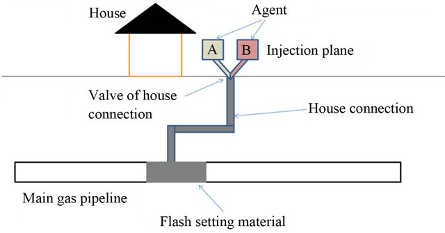
Figure 7. Illustration of the preparation kit to shut off the gas supply.
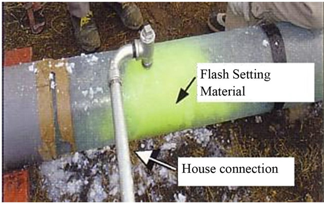
Figure 8. Photo of the preparation kit to shut off the gas supply.
properties of the injected fly ash mixture into a heavily damaged gas pipeline by an earthquake, different combinations of fly ash, chemical agents and water were considered by means of several experiments. As a result, the mixture of A agent, which is a 30% solution of silicic acid sodium, and the B agent of cement, fly ash, the adhesive, the swelling agents are able to accomplish these objectives.
REFERENCES
- Centre for Coal Utilization, “Report on Nationwide Survey on Coal Ash Circumstances,” 2005.
- Environmental Technical Association, “Coal Ash Handbook,” 2005.
- E. Nonveiller, “Grouting Theory and Practice,” 1989.
- Agency of Natural Resources and Energy, “Gas Industry Earthquake Counter-measures Study Report,” 1996.
- F. Yamazaki, T. Katayama, S. Noda, Y. Yoshikawa and Y. Otani, “Development of Large-Scale City-Gas Network Alert System Based on Monitored Earthquake Ground Motion,” Proceedings of JSCE, Vol. 525, 1995, pp. 331- 340.
- Y. Shimizu, S. Yasuda, I. Morimoto and R. P. Orense, “Development of Sensor for Monitoring Seismic Liquefaction,” Soils and Foundations, Vol. 42, No. 1, 2002, pp. 35-52. doi:10.3208/sandf.42.35
- JFA (Japan Fly ash Association), “Coal Ash Handbook,” 1995.
- Centre for Coal Utilization, “Report on Development of Coal Utilization Technology Development Strategy for the 21st Century,” 2003.
- R. E. Davis, “A Review of Pozzolanic Materials and Their Use in Cement Concrete,” 1949.
- R. C. Joshi and E. A. Rosauer, “Pozzolanic Activity in Synthetic Ashes,” American Ceramic Society Bulletin, Vol. 52, No. 5, 1973, pp. 456-463.
- H. Shimada, T. Sasaoka, S. Kubota, K. Matsui and Y. Yoshida, “The Application of Fly Ash Cement in Mining Backfill Material,” Proceedings of International Symposium on Mine Planning & Equipment Selection, Kalgoorlie, April 2003, pp. 199-204.
- Y. Yoshida, H. Shimada, J. Gottfried, M. Iino, K. Matsui, M. Ichinose, S. Fujita, M. Mineshita, T. Mizunuma, T. Kawai and E. Sakai, “Application of Injection Material for Rehabilitation of Pipeline Using Fly Ash-Surfactant Mixtures,” Proceedings of 10th Conference on Environment and Mineral Processing, Ostrava, 2006, Vol. 1, pp. 93-100.
- R. H. Karol, “Chemical Grouting and Soil Stabilization,” 2003.