Journal of Surface Engineered Materials and Advanced Technology
Vol.2 No.3A(2012), Article ID:21436,5 pages DOI:10.4236/jsemat.2012.223036
Lithography and Fabrication of Frictional Tiers on Poly(Dimethylsiloxane) Using Atomic Force Microscopy
![]()
School of Pharmacy and Molecular Sciences and Centre for Biodiscovery and Molecular Development of Therapeutics, James Cook University, Townsville, Australia.
Email: *jolanta.watson@jcu.edu.au
Received May 9th, 2012; revised June 13th, 2012; accepted June 20th, 2012
Keywords: Stick-Slip; PDMS; Manipulation; Friction; Polymer; AFM
ABSTRACT
This study investigates controlled micro/nano manipulation of polydimethylsiloxane (PDMS) using Atomic Force Microscopy (AFM). Lithographic results revealed stick-slip phenomena along the slow scan direction. Varying the normal loading force, scan size, scan number and contact conditions allowed the control of certain lithographic outcomes e.g., channel spacing. The PDMS surface experienced significant in-plane deformation in response to the tip-induced lateral force. This displacement increased with increasing loading force, creating greater spacing between channels in the slow scan direction. Simultaneous generation of a lateral displacement in the fast scan direction caused a decrease in channel length with increasing loading force due to an increase in static friction with normal force, resulting in a greater surface relaxation, and shorter track length of dynamic friction. By controlling both the loading force and the number of scans over an area, frictional tiers were produced.
1. Introduction
The surface structure and chemistry of polymers affect their functionality for a great range of applications in areas as diverse as biosensors [1,2], corrosion protection [3], semiconductor processing [4], biofouling [5], tissue engineering [6] and biomaterials technology [7]. Some of these applications require precise manipulation of laterally differentiated regions. For example attachment of biological moieties at surfaces and interfaces has shown to be highly dependent on local chemistry at the intended site of attachment [8]. Additionally, the local molecular-scale geometry may promote or hinder attachment events, as in the case of biofilms [9]. To date, however, the effect of frictional properties of surfaces for chemical and biomolecular attachment is a much less understood phenomena.
Controlled micro and nano machining/patterning is now a well-established family of technologies—e.g., directional chemical etching, preferential sputtering by focused ion beams, removal of material by laser ablation, micro-abrasion and other micro-scale mechanical wear mechanisms. More recently Scanning Probe Microscopy (SPM), and particularly the adjunct, Atomic Force Microscopy (AFM), have become another addition to the variety of tools available. While some of the technologies rest on a firm scientific basis, i.e., chemical etching and ion beam sputtering, the underlying science is much less satisfactory in the case of mechanical manipulation by SPM methods.
In this study we demonstrate controlled frictional patterning of a polymer surface (polydimethylsiloxane (PDMS)) using Atomic Force Microscopy (AFM) manipulation. PDMS is a bio-active/selective polymer having a broad range of applications such as materials for biomedical devices [10], molecular stamps [11], hydraulic fluid devices [12] and in soft lithography [13]. By controlling parameters such as loading force, scan size and contact conditions we are able to create lithographic patterns and frictional gradients on the polymer surface.
2. Experimental Details
2.1. Polymer Material Preparation
PDMS (Sylgard®-184, supplied by Dow Corning) is a two part silicone elastomer. The mixed base and curing agent (10:1 weight ratio) were spin-coated onto a silicon wafer substrate and cured in an ambient environment (25˚C and 55% relative humidity) for 48 hours prior to any analysis or manipulation.
2.2. AFM Instrumentation
The work was carried out on a ThermoMicroscope TMX- 2000 Explorer. A 130 × 130 μm2 tripod scanner (z-range of 9.7 μm) was utilized. The analyses were carried out under air-ambient conditions (20˚C - 23˚C and 60% - 70% relative humidity). Contact imaging was carried out in the constant force mode. Under normal topographical imaging conditions, the “over-scan” along the fast scan direction, is typically ca. 25%, and is a general characteristic of SPM instruments. This over-scan feature is intended as a means of removing the static friction feature from images. Thus for 20 × 20 and 10 × 10 μm2 fields of view there were 4 and 2.56 μm over-scans, respectively, in the fast scan direction. The over-scan must be taken into account in this study due to the manipulation taking place along the entire fast scan trace. The outcome was then imaged over a larger field of view with a soft (low spring constant) lever. As a result the imaged areas are quoted as 24 × 20 μm2 and 12.5 × 10 μm2. Imaging of the manipulated regions on the polymer was carried out immediately after alteration of the surface.
2.3. AFM Probes
The characteristics of beam shaped levers (Ultrasharp NT-MDT) employed in the present study are listed in Table 1. The data for tip apex radius of curvature, RTip, tip opening half-angle, Ar and surface chemistry are summarized from the suppliers’ specifications. kN, kL and kT are the lever force constants for normal, longitudinal and torsional deformation, respectively, determined from the resonance method [14] (for kN) and calculated from the expression for a long, thin lever described by Gibson et al. [15] (for kL and kT).
3. Results and Discussion
3.1. Lithography on PDMS from Contact Mode Imaging
Figure 1(a) shows a topographical image taken during the acquisition of a 10 × 10 mm2 image on the spin coated PDMS surface (tip “A”, Table 1). During the progression of the scan the loading force was progressively decreased. The image clearly shows an increase in the number of discontinuities with the decreasing load.
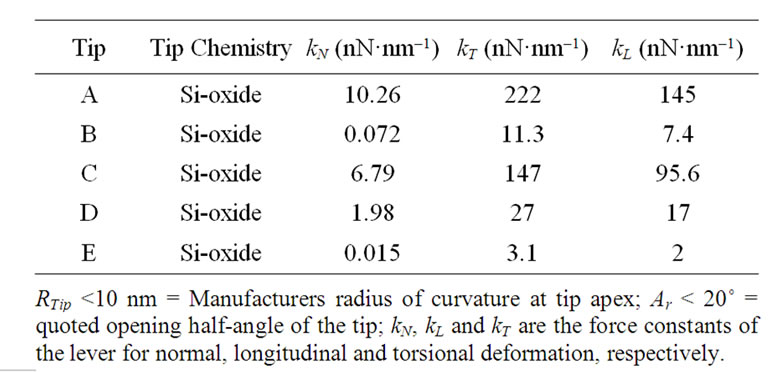
Table 1. Probe characteristics.
The manipulated area shown in Figure 1(a) was then re-imaged over a wider area and using a soft lever (tip “B”, Table 1), with the resulting topographical image shown Figure 1(b). It can be clearly seen that the discontinuities correlate with the channel formation on the polymer surface. As well, channel spacing (along the slow scan direction) increases suggesting that there is significant polymeric stretching and pushing as a result of the increasing loading force. The images indicate an interesting mechanism of tip-induced manipulation of the polymer surface. In the “normal” mode (constant normal force) of operation using AFM on a hard surface e.g., silicon, successive scans along the fast scan direction are implemented by movement of the stage along the slow scan direction resulting in travel of the tip apex equal to the stage movement (for large stage movements of 10’s of nm). This is not the case for the PDMS surface due to the tip being elastically restrained at a stick point. When lateral restraining forces exceed that of the opposing lever-imposed force, while the polymer surface undergoes lateral relaxation, a movement of the stage of many hundreds of nm’s is required before the tip is released to the new equilibrium position. Figure 2 shows a schematic diagram showing the behaviour of the stick-slip mechanism in the slow scan direction. As the tip sticks along the slow scan direction, with each progressive scan in the fast direction it is further embedded/restrained on the surface. However, the stage travel will generate an increasing lateral force. The tip is released when the latter exceeds the restraining force of the channel.
The relationship between loading force and the spacing between channels using tip “C” defined in Table 1 is shown in Figure 3. The results show that the channel spacing increases as the loading force increases due to the tip being embedded deeper into the polymeric surface, thus causing an increase in contact area, greater trapping
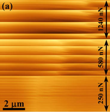
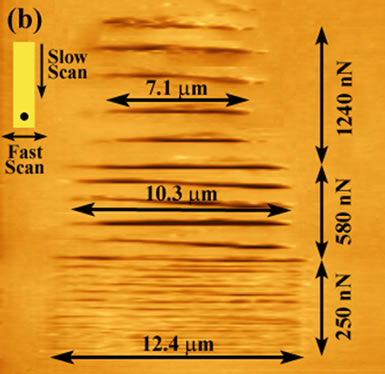
Figure 1. Topographical images (a) revealing lines of discontinuity during a scan (tip “A”, Table 1) and (b) a larger field of view scanned over the previously manipulated PDMS region using a low spring constant lever (tip “B”, Table 1) showing the increase in channel length (from 7.1 mm upto 12.4 mm) with a decrease in loading force. Also, an increase in the spacing of the channels with decreasing normal force is evident.
Figure 2. A schematic showing the stick-slip behaviour in the slow scan direction. With each progressive scan in the fast direction, the tip will create a deeper channel creating a larger potential barrier in the slow scan direction. Simultaneously stage travel will generate a greater lateral force. The tip will escape when the latter exceeds the static “friction” in the slow scan direction. The tip then slips onto its next stick position.
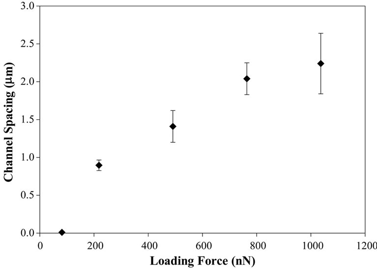
Figure 3. The number of channels decreases with increasing loading force due to the deeper penetration of the tip into the soft polymer surface. This results in an increase in the contact area, a higher “friction” (i.e., strength of confining force) and consequently a greater tip-induced lateral force will be required in order to escape from the stick line. This also results in the depth and channel spacing increasing with loading force.
and consequently greater lateral force required to escape from the trap. This also results in the depth of the channels increasing with loading force.
The channel lengths formed and shown in Figure 1 increase with decreasing loading force. This effect can be attributed to the increase in static friction with normal force, causing greater surface relaxation, and thus a shorter track length of dynamic friction. There is a 2.56 mm overscan in the x-direction (that is, the fast scan direction as seen in the inset in Figure 1(b)) associated with imaging on a “hard” surface over that scan area due to scanner displacement, that is, a 10 × 10 mm2 pre-set scan range will produce an image of 12.56 × 10 mm2. In Figure 1 the resultant channel length for a 250 nN loading force is 12.4 mm. As the polymer deforms, it restricts the tip from scanning across its full range of 12.56 × 10 mm2. Therefore, the channel is 0.16 mm short of a full scan at a loading force of 250 nN, 2.26 mm at 580 nN and 5.46 mm at 1240 nN.
3.2. Fabrication of Frictional Gradients
The PDMS sample was also raster scanned at low loading forces (100 nN) over a 20 × 20 μm2 field of view. The scan was undertaken using a moderately low spring constant, kN, of ca. 2 nN·nm–1 (probe “D” in Table 1). The area was later re-imaged over a larger field of view using a very low spring constant lever (probe “E”, Table 1) in order to observe any changes. Figure 4 shows a lateral force image after manipulation has taken place (contact mode imaging in a raster pattern). At relatively low force loadings the outcome of the manipulation process shows a region exhibiting higher friction in relation to the surrounding unmodified polymer surface. A similar effect has been observed on other polymer surfaces (e.g., [16] and [17]).
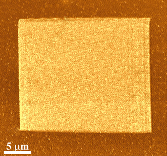
Figure 4. Friction (Lateral) force image of a manipulated region using a lower force loading (ca. 100 nN) showing a uniform laterally differentiated region.
By repetitive scanning across the polymer it was possible to create frictional patterning and frictional gradients with good spatial resolution. The frictional force image in Figure 5 shows three manipulated regions within a single field of view, with the corresponding friction loops revealing higher friction on the manipulated regions. Squares A and B are the result of three and four manipulation scans, respectively, using a high spring constant lever. The corresponding friction loops show the difference in friction in the two squares, i.e., DFL of square A is lower than that of square B. The RMS surface roughness of the manipulated regions was higher than unmodified surface regions. For example the RMS value on square B was found to be higher (~2.8 nm) than that of the surrounding PDMS surface (~1.8 nm), for a 4 ×4 mm2 area. Square C is the result of two scans over a 20 ×20 mm2 area, with a subsequent scan over a 10 ×10 mm2 area (square D), creating a frictional “tier”.
The frictional gradients can also be viewed as 3 dimensional profiles where higher regions are indicative of a higher frictional response (Figure 6). In this particular example the conditions of manipulation are similar to that for Figure 5 squares C & D however the first scan is over a wider area and the higher frictional tier is the result of 2 further scans.
Figure 7 demonstrates the flexibility and control of the technique with a variety of frictional architectures created on the PDMS surface by altering the loading force, scan size and the number of successive scans. The image shows both isotropic and anisotropic features overlapping. Squares A, B, D and E were created by maintaining a force loading below the point at which stick-slip is induced, thereby creating uniformly frictionally altered regions. Several squares overlap creating multi frictional “tiers”, e.g., squares A, B and C. Stick-slip effects are apparent on square C.
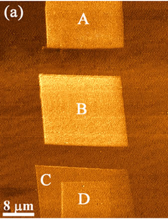
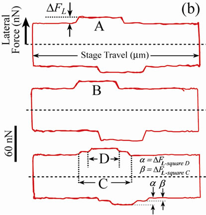
Figure 5. A frictional force image showing four square regions created by altering the number of successive scans; three for square A, four for square B, and two for square C. Square D is a result of scanning over square C once. The corresponding friction loops show higher friction created as a result of the scans.

Figure 6. A frictional force image showing a larger rectangular and one square region. The larger square is the result of two scans across a larger area. The smaller square was formed by a Further 2 repetitive scans over that area.
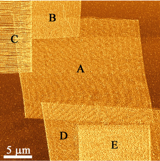
Figure 7. Frictional force image showing the degree of freedom in feature formation on the polymer surface.
4. Conclusions
In the process of imaging the PDMS surface with a stiff lever, various image discontinuities were observed. After imaging over the same area with a soft lever, these were determined to be the result of stick-slip phenomena. An explanatory model is presented in order to understand the process. The data revealed that an increasing loading force results in an increase in the in-plane displacement of the surface and the spacing between the channels.
By altering the scanning conditions it is possible to carry out frictional tuning on a polymer surface (in this case PDMS) at the micro and nano scales. The frictional patterning can be carried out to form intricate frictional profiles. The two distinct different forms of patterning can achieve both isotropic and anisotropic frictional surface profiles using manipulative atomic force microscopy. The pattered surfaces may have applications in regard to selective patterning and separation of biological molecules.
REFERENCES
- M. Gerard, A. Chaubey and B. D. Malhotra, “Application of Conducting Polymers to Biosensors,” Biosensors and Bioelectronics, Vol. 17, No. 5, 2002, pp. 345-359. doi:10.1016/S0956-5663(01)00312-8
- K. E. Geckeler and B. Müller, “Polymer Materials in Biosensors,” Naturwissenschaften, Vol. 80, No. 1, 1993, pp. 18-24. doi:10.1007/BF01139752
- M. Rohwerder and A. Michalik, “Conducting Polymers for Corrosion Protection: What makes the Difference between Failure and Success?” Electrochimica Acta, Vol. 53, No. 3, 2007, pp. 1300-1313. doi:10.1016/j.electacta.2007.05.026
- J. Y. Kim, K. Lee, N. E. Coates, D. Moses, T.-Q. Nguyen, M. Dante and A. J. Heeger, “Efficient Tandem Polymer Solar Cells Fabricated by All-Solution Processing,” Science, Vol. 317, No. 5835, 2007, pp. 222-225. doi:10.1126/science.1141711
- C. M. Grozea and G. C. Walker, “Approaches in Designing Non-Toxic Polymer Surfaces to Deter Marine Biofouling,” Soft Matter, Vol. 5, No. 21, 2009, pp. 4088- 4100. doi:10.1039/b910899h
- K. Rezwan, Q. Z. Chen, J. J. Blaker and A. R. Boccaccini, “Biodegradable and Bioactive Porous Polymer/Inorganic Composite Scaffolds for Bone Tissue Engineering,” Biomaterials, Vol. 27, No. 18, 2006, pp. 3413-3431. doi:10.1016/j.biomaterials.2006.01.039
- D. G. Anderson, D. Putnam, E. B. Lavik, T. A. Mahmood and R. Langer, “Biomaterial Microarrays: Rapid, Microscale Screening of Polymer-Cell Interaction,” Biomaterials, Vol. 26, No. 23, 2005, pp. 4892-4897. doi:10.1016/j.biomaterials.2004.11.052
- C. de las Heras Alarcón, S. Pennadam and C. Alexander, “Stimuli Responsive Polymers for Biomedical Applications,” Chemical Society Reviews, Vol. 34, No. 3, 2005, pp. 276-285. doi:10.1039/b406727d
- K. Anselme, P. Davidson, A. M. Popa, M. Giazzon, M. Liley and L. Ploux, “The Interaction of Cells and Bacteria with Surfaces Structured at the Nanometre Scale,” Acta Biomaterialia, Vol. 6, No. 10, 2010, pp. 3824-3846. doi:10.1016/j.actbio.2010.04.001
- A. Mata, A. J. Fleischman and S. Roy, “Characterization of Polydimethylsiloxane (PDMS) Properties for Biomedical Micro/Nanosystems,” Biomedical Microdevices, Vol. 7, No. 4, 2005, pp. 281-293. doi:10.1007/s10544-005-6070-2
- H. Tokuhisa and P. T. Hammond, “Nonlithographic Microand Nanopatterning of TiO2 Using Polymer Stamped Molecular Templates,” Langmuir, Vol. 20, No. 4, 2004, pp 1436-1441. doi:10.1021/la030191u
- G. M. Whitesides, “The Origins and the Future of Microfluidics,” Nature, Vol. 442, No. 7101, 2006, pp. 368-373. doi:10.1038/nature05058
- G. M.Whitesides, E. Ostuni, S. Takayama, X. Jiang and D. E. Ingber, “Soft Lithography in Biology and Biochemistry,” Annual Review of Biomedical Engineering, Vol. 3, 2001, pp. 335-373. doi:10.1146/annurev.bioeng.3.1.335
- J. P. Cleveland, S. Manne, D. Bocek and P. K. Hansma, “A Nondestructive Method For Determining The Spring Constant Of Cantilevers For Scanning Force Microscopy”, Review of Scientific Instruments, Vol. 64, No. 3, 1993, pp. 403-405. doi:10.1063/1.1144209
- C. T. Gibson, G. S. Watson and S. Myhra, “Scanning Force Microscopy—Calibration Procedures for ‘Best Practice’,” Scanning, Vol. 19, No. 8, 1997, pp. 564-581. doi:10.1002/sca.4950190806
- G. Haugstad, W. L. Gladfelter and R. R. Jones, “Scanning force Microscopy Characterization of Viscoelastic Deformations Induced by Precontact Attraction in a Low Cross-Link Density Gelatine Film,” Langmuir, Vol. 14, No. 14, 1998, pp. 3944-3953. doi:10.1021/la9713107
- R. H. Schmidt, G. Haugstad and W. L. Gladfelter, “Scan Induced Patterning and the Glass Transition in Polymer Films: Temperature and Rate Dependence of Plastic Deformation at the Nanometer Length Scale,” Langmuir, Vol. 19, No. 24, 2003, pp. 10390-10398. doi:10.1021/la0348564
NOTES
*Corresponding author.