World Journal of Engineering and Technology
Vol.05 No.04(2017), Article ID:79556,8 pages
10.4236/wjet.2017.54B014
Experimental Study on Electrostatically Actuated Micro-Gripper Based on Silica Process
Pengnian Yang, Yuhe Li, Yong Li, Qingxiang Li
Department of Precision Instruments and Mechanology, Tsinghua University, Beijing, China


Received: September 18, 2017; Accepted: October 9, 2017; Published: October 12, 2017
ABSTRACT
The characteristics of a kind of comb-drive electrostatic actuated micro-gripper are tested. The test platform using a microscope-CCD-computer, the state information of the micro-gripper obtained by data acquisition and image processing, voltage-displacement characteristic curve is obtained and the mathematical equation is established. The analysis of the characteristic equation has shown the consistency and rationality of the theoretical design and the experimental results. The main factors that cause the difference between the theoretical design and the actual test performance are analyzed, and the design method and experimental results is obtained for the micro-gripper in the field of micro-assembly.
Keywords:
Micro-Gripper, Image Process, Experimental Analysis

1. Introduction
There is currently a lack of full understanding that the law of motion of the mechanical system in microscopic conditions, physical and mechanical properties of small components behavior. The theory of micro-system design and methods has not yet formed perfect. As a kind of important method, the micro-device detection technology, not only can test the quality of micro-devices and micro-electromechanical systems, but also provides a means of verification for the basic theoretical research.
Micro-gripper is a main tool of micro-operation, which can link the macro and micro-world. The main body of the proposed micro-gripper is micro-clamp based on cantilever beam, with the advantages of large output force and large displacement [1], as shown in Figure 1. The micro-gripper is actuated electrostatically
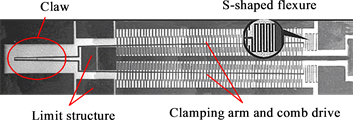
Figure 1. Electrostatically actuated micro-gripper based on silicon bulk micromachining process.
by a kind of comb structure based on the bulk silicon process. The gripper is composed of micro-claw, limit structure and comb driver. In order to reduce the internal stress, the clamping arm is designed as an S-shaped flexible structure. The micro-gripper has a large depth-width ratio: the structure thickness is 60 μm; the comb width is 6 μm, the depth-width ratio is 10:1; the comb tooth gap is 4 μm, the depth-width ratio is 15:1, the maximum size of the micro-gripper is 2465 μm, and the opening and closing value of the gripper is 12 - 140 μm. The clamping arm is used as a conductor and ground, the actuation mode of the fixed comb tooth with driving voltage, electrostatic drive will not be a negative impact on the object being held. The gripper has the characteristics of simple technology, profitable controllability, large clamping range and holding force. It is suitable for many micro-operation tasks.
2. Micro-Gripper Test
2.1. Test System
Electrostatic actuated micro-gripper is the electromechanical coupling device. The input is voltage and the output is mechanical displacement. The micro-gripper is tested by electrostatic actuated open-loop control. The tip of the micro-gripper has a displacement range of only a few dozen microns, and it is impossible to measure by conventional geometrical measurement tools. The microscope-CCD-computer test scheme is adopted as shown in Figure 2. Micro-gripper magnified by microscope and CCD-camera, the image processing and information collection are obtained by computer. The range of drive voltage of micro-clamp is set at 0 - 80 V. The battery power supply is adopted in order to reduce the electromagnetic interference.
During the test, it was found that the parasitic charge generated by the device itself and the electrostatic interference of the external environment had a great influence on the micro-gripper. The main reason was as follows: when the driving voltage was not applied, the micro-clamping arm was in the deflecting position. The phenomenon of limit structure occurred by micro-clamping arm contacts to the instruments, workstations and other operators. These problems greatly affect the micro-gripper characteristics of the test work. Therefore, avoiding electrostatic interference is the main task to ensure the smooth operation of the experiment. External electrostatic interference can be avoided by controlling

Figure 2. Schematic of test system for micro-gripper.
the environmental humidity, avoiding the electrostatic objects contact with micro-devices and their leads, lead grounding and other methods. Grounding the individual electrodes is a method to prevent the parasitic charge of the devices affecting themselves when the micro-gripper is stored.
2.2. Data Processing
In order to obtain the value of opening and closing of the micro-gripper at different voltages, it is necessary to quantize the collected images. The original image is collected, as shown in Figure 3. It is difficult to quantify it for the following reasons:
・ The contrast and boundary of image is not obvious because the surface of gripper sputtered the gold film as the lead bonding layer.
・ The “shadow” area of the no aurum film is obvious due to the structure block during the production of micro-gripper.
・ Impurity interference in the image.
It can be seen that the quality of the restored image is poor. Therefore, the following image processing methods are used [2]:
1) Adjust the gray scale distribution. The original image of the gray distribution is very narrow, as shown in Figure 4. Grayscale histogram shows the distribution of gray value strength. It is difficult to distinguish between the objects and background directly. The gray value of 100 - 255 pixels shows a good enhancement effect.
2) Edge extraction. As shown in Figure 5. If the gray value of the column pixel is quantified directly, it is hard to select the gray threshold of the boundary of the micro-clamping arm. Therefore, the Sobel operator is used to extract the edge, and the result is shown in Figure 6. Compared with the original image, the edge extraction method can detect the micro-clamping arm contour accurately, but the side of the edge is blurred.
3) Quantitative processing. The pixels in the x1 - x2 region in Figure 5, are projected onto x0 along the Y axis. As x1x0 = x0x2 , according to the regularity and probability principle of the image distribution, the center of the Y-direction of the micro-clamping arm after projection is coincident or has a little error with the actual position, the deformation value of micro-clamping arm tip can be acquired by searching along from x0. The intersections of x0 axis and y2 axis, y3 axis are the quantization result as shown in Figure 5.

Figure 3. Original image of micro-gripper.

Figure 4. Grayscale histogram of original image.

Figure 5. Result of image process.

Figure 6. Image of edge detection.
3. Experimental Analysis
3.1. Displacement Characteristics
The quantitative process of the image collected by the micro-gripper at different drive voltages, voltage-displacement characteristic curve obtained by the displacement variation from equilibrium to the closure process, as shown in Figure 7. The discrete data is quadratic.
In the form of:
The voltage-displacement equation of the micro-gripper can be described as:
(1)
where u is the applied drive voltage and d (u) is the displacement of the tip of the micro-gripper at drive voltage u.
There are three items in Equation (1).
1) a2u2 = 0.11092u2 indicate the working characteristics of the comb electrostatic actuator, the electrostatic force is independent of the displacement and is proportional to the square of the driving voltage. The single interdigital comb electrostatic actuator model is shown in Figure 8.

Figure 7. Voltage-displacement characteristic of micro-gripper.

Figure 8. Model of comb-drive actuator.
d represents the interdigital spacing, h and t are width and thickness, l is the overlapping length of the moving finger, and g is the distance between the tip of the fork and the root of the corresponding fork. The electrostatic driving force is expressed as [3]:
(2)
where C is the capacitance of the interdigitated structure and ε is the dielectric constant. Εt/d in Equation (2) corresponds to a2, which reflects the structural parameters of the comb driver.
2) a1u = −0.13808u shows that the displacement of the micro-clamping arm has a linear relation with the driving voltage, because the micro-clamping arm has a rigid connection with the fixed end, therefore, the stress and the displacement of micro-clamping arm is proportional. This form indicates the stress caused by the displacement of the micro-clamping arm.
3) a0 = 0.47233 shows the error of the test system is mainly from the accuracy of the image recognition and the error of the quadratic fitting. The error of the former is about 0.3 μm, and the error of the quadratic fitting constant is 0.19655. Therefore, the existence and the size of a0 are reasonable.
Equation (2) indicates the relationship between the driving voltage and the micro-clamping arm in the unloading state. This above analysis shows the rationality and provides the basis for the open-loop control of the micro-gripper.
3.2. Design Error Analysis
According to the design parameters, the drive voltage is 47.5 V when the micro-clamping arm moved to the maximum displacement, but the drive voltage during test is only 14.5 V. This difference reflects the design error, the errors of micro-clamping force and micro-clamping arm displacement are mainly caused by the following areas [4] [5]:
Difference between actual size and design value. The actual geometrical dimensions of the micro-gripper are shown in Figure 9, (design dimensions in brackets), indicating that the actual dimensions of the device differ from the design size greatly. There are many reasons for the difference in geometric dimensions: first, the alignment error of the mask pattern is ±0.3 μm, in the photolithography process, the deformation of the graphics size accuracy caused by overexposure or underexposure, also introduction of errors, which lead to micro-mechanical parts of the location and size of the low accuracy. Second, in the process of ICP deep etching, the difference of the factors such as the structure, material and the corrosion temperature result the errors of the geometry size on the different parts of the same device. During the test, the proportion between actual size of the processing and the design value is 0.85 - 0.90. The mechanical inertia is only 0.729 (0.93) times of the design value. This makes the micro-clamping arm more flexible.

Figure 9. SEM image of microgripper.
Electrostatic force estimation error. The Equation (2) is used as the calculation formula of the electrostatic force, which does not take into account the edge effect of the capacitor, but the edge effect is obvious that the ratio of the actual side length to the comb tooth gap is 7.5 - 15, therefore, the actual driving force of the comb drive is higher than the design value, the micro-clamping force output will be better than the design value.
Effect of material properties on the gripper. Monocrystalline silicon elastic modulus distribution between 125 - 202 GPa [6], the design used in the value is 169 GPa, is about the commonly used monocrystalline silicon elastic modulus of the median. Uncertainty in material performance, the design phase accurately estimates the performance of the device.
The effect of erosion on the gripper. The main problems in the process of inductively coupled plasma (ICP) etching are etch and hysteresis. Etching phenomenon is the main factor in this case. As shown in Figure 10. When erosion happened, lateral etching leading to a rapid decrease in the depth direction of the structure. The width of the slot has a great impact on the etching rate. The higher the width of the groove, the faster the etch rate is, and the effect on the fine structure is significant. The etching phenomenon happened even in normal etch process, especially when the structure has a large depth-width ratio, it will lead to the difference between the depth direction size and the design value in the structure.
4. Conclusions
The test method of the voltage-displacement characteristic curve of the micro-gripper is feasible, and the characteristic equation of the micro-gripper is obtained by the microscope-CCD-computer test system. The analysis of the characteristic equation shows the consistency and rationality of the theoretical design and the experimental results. It is different between micro-mechanical design and macro-mechanical because of the particular nature of micro devices,

Figure 10. Schematic of footing effect.
therefore, the rule of electrostatically actuated based microscale structure still need to further study and improve.
This research work was supported by the National Natural Science Foundation of China under Grant No.61362035, No.51275259 and the National Important Scientific Instrument Development Program of China under Grant No. 2011YQ030134.
Cite this paper
Yang, P.N., Li, Y.H., Li, Y. and Li, Q.X. (2017) Experimental Study on Electrostatically Actuated Micro-Gripper Based on Silica Process. World Journal of Engineering and Technology, 5, 126-133. https://doi.org/10.4236/wjet.2017.54B014
References
- 1. Millet, O., Bernardoni, P., Régnier, S., Bidaud, P., Tsitsiris, E., Collard, D. and Buchaillot, L. (2004) Electrostatic Actuated Micro Gripper Using an Amplification Mechanism. Sensors and Actuators A: Physical, 114, 371-378. https://doi.org/10.1016/j.sna.2003.11.004
- 2. Tang, W.C., Nguyen, T.H. and Howe, R.T. (1989) Laterally Driven Polysi-clion Resonant Structures. Proc. IEEE Micro Electro Mechanical Systems Workshop, February 1989, 53-59.
- 3. Legtenberg, R., Groeneveld, A.W. and Elwenspoek, M. (1996) Comb-Drive Actuators for Large Displacements. Journal of Micromechanics and Microengineering, 6, 320. https://doi.org/10.1088/0960-1317/6/3/004
- 4. Reaz, M.B.I., Hussain, M.S. and Mohd-Yasin, F. (2006) Techniques of EMG Signal Analysis: Detection, Processing, Classification and Applications. Biological Procedures Online, 8, 11-35. https://doi.org/10.1251/bpo115
- 5. Bhushan, B. and Li, X.D. (1997) Micromechanical and Tribological Characterization of Doped Single-Crystal Silicon and Polysilicon Films for Microe-lectromechanical Systems Devices. J. Mater. Res, 1997, 54-63. https://doi.org/10.1557/JMR.1997.0010
- 6. Wu, J.G. and Bin, H.Z. (2007) Dimensional Inspecting System of Thin Sheet Parts Based on Machine Vision. Optics and Precision Engineering, 1, 22.