J. Biomedical Science and Engineering, 2011, 4, 651-656
doi:10.4236/jbise.2011.410081 Published Online October 2011 (http://www.SciRP.org/journal/jbise/
JBiSE
).
Published Online October 2011 in SciRes. http://www.scirp.org/journal/JBiSE
The role of hardness and roughness on the wear of different
CoCrMo counterfaces on UHMWPE for artificial joints
V ictor A. González-Mora1, Michael Hoffmann1, Rien Stroosnijder1, F. Javier Gil2
1Institute for Health and Consumer Protection, Joint Research Centre, European Commision, Ispra, Italy;
2Department of Materials Science and Matallurgical, Technical University of Catalonia, Barcelona, Spain.
Email: francesc.xavier.gil@upc.edu
Received 19 April 2011; revised 12 May 2011; accepted 2 September 2011.
ABSTRACT
Wear tests were carried out to study the effect of the
hardness and roughness with various counterface
materials on UHMWPE wear behaviour. The materi-
als used as counterfaces were based on varieties of
CoCrMo: 1) forged (hand-polished) CoCrMo, 2)
forged (mass-finished) CoCrMo, and 3) cast (mass-
finished) CoCrMo. Additionally, two coatings were
proposed: 1) a CoCrMo coating applied to the forged
CoCrMo alloy by means of physical vapour deposi-
tion (PVD), and 2) a ZrO2 coating applied to the
forged CoCrMo alloy by means of plasma-assisted
chemical vapour deposition (PACVD). The recipro-
cating pin-on-flat (RPOF) device for pin-on-disk
wear testing was used for this study. The worn sur-
faces were observed using optical, atomic force and
scanning electron microscopes.
Keywords: Wear; Artificial Joints; CoCrMo; Hardness;
Roughness
1. INTRODUCTION
The total replacement of damaged or diseased synovial
joints represents the greatest advance in orthopaedic
surgery the last century [1]. The ability to replace dam-
aged joints with prosthetic implants has brought relief to
millions of patients who would otherwise have been
severely limited in their most basic activities and re-
signed to a life of pain [1,2].
Actual material combinations are based on a polymer
component for the acetabular cup in the hip joint or the
tibial plateau in the knee joint, and a metallic or ceramic
counterface for the femoral head in the hip joint or the
femoral condyle in the knee joint. Specifically for the
polymeric component, the Ultra High Molecular Weight
Polyethylene (UHMWPE) has been universally adopted.
At present, the couple or sliding pair composed by
UHMWPE and a metallic counterface (currently a CoCr-
based alloy) are the most widely applied. This material
combination is referred to as polyethylene-on-metal arti-
ficial joint. Another possibility for the counterface mate-
rial is use of a ceramic material, this is referred to as a
polyethylene-on-ceramic (alumina and zirconia are the
most relevant ceramic materials). In the last years a re-
newed interest for two different concepts has developed.
These are the metal-on-metal and ceramic-on-ceramic
artificial joints [3,4].
When the natural joint has to be replaced with artifi-
cial materials, there is a change in the tribological situa-
tion due to the inability of the actual materials used to
produce an artificial permanent lubricating film. There-
fore, the materials used for articulating components in an
artificial joint are always subject to wear. Furthermore,
there is no ideal bearing material that currently fulfils all
the requirements of arthroplasty design [5-7]. Importan-
tly therefore wear has to be minimised to avoid possible
aseptic loosening following osteolysis due to particle-
initiated foreign body reaction [8,9].
The articulating surfaces of a total joint replacement
are recognised as major sources of wear debris genera-
tion. Accurate laboratory wear simulations are essential
for evaluating candidate materials and designs, because
it is neither practical nor justified to evaluate the nume-
rous potential design alternatives through clinical trials.
By means of laboratory wear tests, useful tribological
information can be produced for clinical assessment of
new designs, materials, surface treatments, coatings, etc.
2. MATERIALS AND METHODS
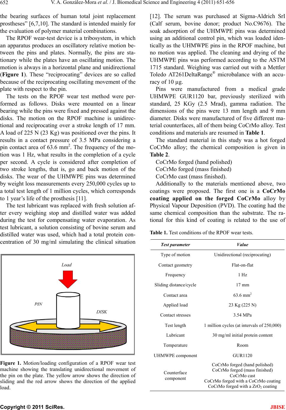
A reciprocating pin-on-flat (RPOF) device is a special
pin-on-disk (POD) wear tester that was designed in ac-
cordance with the ASTM F732-82 standard. This stan-
dard is the first specific standard in the field of biotri-
bology. It sets guidelines for a “laboratory method for
evaluation of the friction and wear properties of combi-
nations of materials that are being considered for use as
V. A. González-Mora et al. / J. Biomedical Science and Engineering 4 (2011) 651-656
652
the bearing surfaces of human total joint replacement
prostheses” [6,7,10]. The standard is intended mainly for
the evaluation of polymer material combinations.
The RPOF wear-test device is a tribosystem, in which
an apparatus produces an oscillatory relative motion be-
tween the pins and plates. Normally, the pins are sta-
tionary while the plates have an oscillating motion. The
motion is always in a horizontal plane and unidirectional
(Figure 1). These “reciprocating” devices are so called
because of the reciprocating oscillating movement of the
plate with respect to the pin.
The tests on the RPOF wear test method were per-
formed as follows. Disks were mounted on a linear
bearing while the pins were fixed and pressed against the
disks. The motion on the RPOF machine is unidirec-
tional and reciprocating over a stroke length of 17 mm.
A load of 225 N (23 Kg) was positioned over the pins. It
results in a contact pressure of 3.5 MPa considering a
pin contact area of 63.6 mm2. The frequency of the mo-
tion was 1 Hz, what results in the completion of a cycle
per second. A cycle is considered after completion of
two stroke lengths, that is, go and back motion of the
disks. The wear of the UHMWPE pins was determined
by weight loss measurements every 250,000 cycles up to
a total test length of 1 million cycles, which corresponds
to 1 year’s life of the prosthesis [11].
The test lubricant was replaced with fresh solution af-
ter every weighing stop and distilled water was added
during the test for compensating water evaporation. As
test lubricant, a solution consisting of bovine serum and
distilled water was used, which had a total protein con-
centration of 30 mg/ml simulating the clinical situation
Figure 1. Motion/loading configuration of a RPOF wear test
machine showing the translating unidirectional movement of
the pin on the plate. The yellow arrow shows the direction of
sliding and the red arrow shows the direction of the applied
load.
[12]. The serum was purchased at Sigma-Aldrich SrI
(Calf serum, bovine donor; product No.C9676). The
soak adsorption of the UHMWPE pins was determined
using an additional control pin, which was loaded iden-
tically as the UHMWPE pins in the RPOF machine, but
no motion was applied. The cleaning and drying of the
UHMWPE pins was performed according to the ASTM
1715 standard. Weighing was carried out with a Mettler
Toledo AT261DeltaRange® microbalance with an accu-
racy of 10 µg.
Pins were manufactured from a medical grade
UHMWPE GUR1120 bar, previously sterilized with
standard, 25 KGy (2.5 Mrad), gamma radiation. The
dimensions of the pins were 13 mm length and 9 mm
diameter. Disks were manufactured of five different ma-
terial counterfaces, all of them being CoCrMo alloy. Test
conditions and materials are resumed in Table 1.
The standard material in this study was a hot forged
CoCrMo alloy; the chemical composition is given in
Table 2.
CoCrMo forg ed (hand polished)
 CoCrMo forged (mass finished)
 CoCrMo cast (mass finished).
Additionally to the materials mentioned above, two
coatings were proposed. The first one is a CoCrMo
coating applied on the forged CoCrMo alloy by
Physical Vapour Deposition (PVD). The coating had the
same chemical composition than the substrate. The ra-
tional for this kind of coating is related to the use of
Table 1. Test conditions of the RPOF wear tests.
Test parameter Value
Type of motion Unidirectional (reciprocating)
Contact geometry Flat-on-flat
Frequency 1 Hz
Sliding distance/cycle17 mm
Contact area 63.6 mm2
Applied load 23 Kg (225 N)
Contact stresses 3.54 MPa
Test length 1 million cycles (at intervals of 250,000)
Lubricant 30 mg/ml initial protein content
Temperature Room
UHMWPE componentGUR1120
Counterface
component
CoCrMo forged (hand polished)
CoCrMo forged (mass finished)
CoCrMo cast
CoCrMo forged with a CoCrMo coating
CoCrMo forged with a ZrO2 coating
C
opyright © 2011 SciRes. JBISE
V. A. González-Mora et al. / J. Biomedical Science and Engineering 4 (2011) 651-656 653
Tab le 2. Chemical composition of the forged CoCrMo alloy in
%.
Element Cr Mo MnNi Si Fe CN
Balance 26 - 30 5 - 7 max
1
max
1
max
1
max
0.7
max
0.35
max
0.25
femoral components in Total Knee Replacements (TKRs)
The other coating applied on the  forged CoCrMo
alloy was a ZrO2 coating applied by plasma assisted
chemical vapour deposition (PACVD). The rationale for
testing this coating is the same as for the CoCrMo coat-
ing CoCrMo forged with a ZrO2 coating
For each counterface material, four disks were tested
and at less, three of them were considered for evaluation.
A total of 40 wear tests were performed. The roughness
and the hardness of each material can be observed in
Table 3.
3. EXPERIMENTAL RESULTS AND
DISCUSSION
The wear results obtained with the RPOF test method for
the UHMWPE specimens (pins) are shown in Figure 2,
where the volumetric wear (mm3) of the UHMWPE pins
is represented as a function of test duration (in cycles)
and the different counterfaces. The volumetric wear re-
sults are calculated form the average weight loss of three
specimens per each material.
The results show that the CoCrMo coating causes the
highest UHMWPE wear of all counterfaces tested. The
CoCrMo coating wear rates in an order of magnitude
higher than that produced by the mass finished (forged)
alloy, which in this study causes the least UHMWPE
wear. The ZrO2 coating and the hand polished (forged)
CoCrMo alloy produce intermediate UHMWPE wear
rates. The wear rates show a UHMWPE wear value for
the ZrO2 coating about the half of the CoCrMo coating.
Standard deviations vary between 0.01 and 0.05 mg,
except for the CoCrMo coating. The implication of this
Figure 2. Average volumetric wear of UHMWPE pins sliding
against different counterfaces.
measurement variation is that with little weight loss of
the UHMWPE the gravimetric wear determination is
highly affected form the intrinsic uncertainty of the
measurement. So that for the very early stages and espe-
cially for counterfaces producing very little weight loss
of the UHMWPE specimen, the measurements are af-
fected of a high uncertainty. Regarding the CoCrMo
coating, it had significantly higher standard deviations
ranging from 0.08 to 0.11 mg. The greater scatter for the
CoCrMo coating is thought to be due to the higher sensi-
tivity of the coating to scratches and third-body wear
which highly influence the surface roughness of the
disks and subsequently the weight loss of the UHMWPE.
The microhardness measurements were performed to
investigate, whether a correlation between the UHMWPE
wear and the Vickers microhardness of the counterface
have been established. The results of Tab le 3 show that
the mass finishing treatment on the surface of the forged
CoCrMo alloy increases the microhardness of the mate-
rial about 25% when compared with the hand polished
forged, showing the increase in hardness by means of the
mass finishing treatment. The reason of the hardness
increase in mass finished alloys is due to the impact of
the abrasive inert particles during the process, which
produce a state of deformation on the surface. The Co-
CrMo coating shows the highest value while the ZrO2
coating shows the lower hardness value.
Hardness ranking agrees with the wear results and sur-
face observations for the bulk counterfaces. From Fig-
ure 3 can be observed the relationship between the mi-
crohardness versus wear rates. Thus, the mass finished
(forged) alloy causes less UHMWPE wear than the mass
finished (cast) alloy and the later causes less UHMWPE
wear, at least for the bulk material. In the same order,
mass finished (forged) CoCrMo alloy is harder than the
mass finished (cast) alloy and latter is harder than the
hand polished (forged) alloy, as can be observed in Fig-
ure 3. As the figure shows, there is a linear ship between
counterface hardness and UHMWPE wear, at least for
the bulk materials. Therefore, the harder a surface is the
less UHMWPE wear causes. The effect of the counter-
face hardness in the UHMWPE wear is due to the fact
Table 3. Roughness and hardness for each material tested.
Material Roughness Ra (µm) Hardness (HVN)
Hand Polished 0.03 ± 0.01 673 ± 21
Mass Polished 0.05 ± 0.01 840 ± 62
Cast CoCrMo 0.05 ± 0.01 783 ± 52
CoCrMo coating 0.10 ± 0.01 884 ± 28
ZrO2 coating 0.06 ± 0.01 575 ± 43
C
opyright © 2011 SciRes. JBISE
V. A. González-Mora et al. / J. Biomedical Science and Engineering 4 (2011) 651-656
654
Figure 3. Vickers microhardness versus wear rate relationship
in the RPOF wear test.
that hard surfaces are more resistant against scratching
and consequently produces less UHMWPE wear, since
an increase in the surface roughening produces an expo-
nential increase in the UHMWPE wear. Indirectly, the
results here discussed indicated that the main wear proc-
ess occurring is abrasive wear and that adhesive wear is
less important or sensitive.
From the material characterisation discussed before, it
is clear that the hand polished counterface has a better
surface finish than the mass finished counterfaces (both
forged and cast). In a first instance, it is reasonable to
think that a rougher surface of the mass finished coun-
terface would produce a higher UHMWPE wear than the
smother surface of the hand polished counterface, since
the wear of an UHMWPE component depends on the
material counterface’s condition. However, the results of
this study shown that this assumption is erroneous and
that when predicting the effect in the UHMWPE wear of
different counterface materials the counterface hardness
are the essential parameter. On the contrary, the surface
roughness of the counterfaces does not appear to be an
important parameter when evaluating the UHMWPE
wear produced by different counterfaces.
The influence of counterface hardness in the
UHMWPE wear resulting from this study resembles the
fact the ceramic counterface causes less UHMWPE wear
than metallic counterfaces, even when having similar
surface finishing. Evidence of reduced UHMWPE from
ceramic counterfaces is given in the literature from both
clinical and laboratory studies [1-4,13]. Hard, stable ce-
ramic surfaces such as Al2O3 or ZrO2 can be expected to
maintain their initial surface finish and thus minimise
UHMWPE wear. On the other hand, metallic counter-
faces can be scratched increasing thus the roughness of
the counterface and the UHMWPE wear [12-15].
The UHMWPE wear caused by the ZrO2 coating
agrees with the assumption that less harder counterfaces
causes more UHMWPE wear. Additionally, AFM and
SEM observation of the worn surfaces have shown su-
perficial defects of the coating itself (Figure 4(a)) oc-
curred during the coating deposition. These defects to-
gether with the irregular mass finished substrate surface
and the well-known fragility of ZrO2 coatings can be the
cause of the coating fracture and subsequent detachment,
which can be observed in Figure 4(b). This kind of coat-
ing failure can produce a high UHMWPE wear. In Fig-
ure 5 can be observed by means AFM.
Regarding the CoCrMo coating, it has the highest
hardness value. This should provide the coating a very
good scratch resistance, at least much than for the bulk
materials investigated. Under the prevailing experimen-
tal conditions, however, the CoCrMo coating produced
the highest UHMWPE wear in this study. Additionally,
the observation of the CoCrMo coating worn surface by
AFM has shown a highly scratched CoCrMo coating
surface and consequently an increase in surface rough-
(a)
(b)
Figure 4. SEM micrographs of the ZrO2 coating surface. (a)
As-received surface showing coating deposition defects see
arrows. (b) Surface after the wear test showing the failure of
the coating by fracture and detachment. The CoCrMo subtract
was identified by EDS analysis.
C
opyright © 2011 SciRes. JBISE
V. A. González-Mora et al. / J. Biomedical Science and Engineering 4 (2011) 651-656 655
(a) (b)
(c) (d)
Figure 5. AFM images of the ZrO2 coating. (a) 25 × 25 μm
image of the virgin surface. (b) 5 × 5 μm image of the virgin
surface. (c) 25 × 25 μm image of the surface on the wear track.
(d) 5 × 5 μm image of the surface on the wear track. The black
arrows show the direction of sliding.
ness, causing high UHMWPE wear. Furthermore, coat-
ing fragments may have favour third body wear mecha-
nisms, roughening too the coating surface.
The as-received surface of the CoCrMo coating ap-
pears very homogenous. The scratches left during the
mass finishing process are not present, since the coating
has covered them (Figures 6(a) and (b)), leaving the
nodules as typical features of the coating deposition.
Compared to the forged CoCrMo alloy, the surface of
the CoCrMo PVD coating has undergone a significant
change after the wear test (Figures 6(c) and 6(d)). The
homogeneous structure of the CoCrMo coating in the
as-received state has completely disappeared and scra-
tches parallel to the sliding direction have formed. It has
been supposed that these scratches have been likely
produced by parts of the coating, which had delaminated
from the coating surface, leading to third-body wear.
This possibility corroborates the higher number of scra-
tches seen by the optical microscope on this material.
Additionally, ridges perpendicular to the sliding direc-
tion have remained on the coating surface. These are the
rests of the nodules left on the coating deposition. Both,
the ridges and scratches are considered responsible for
the observed increase in the surface roughness, causing
the higher UHMWPE wear compared to the forged and
(a) (b)
(c) (d)
Figure 6. AFM images of th × 25 μm
between counterface hardness
Gee, M. (1996) Wear and osteolysis in
,
71534692
e CoCrMo coating. (a) 25
image of the virgin surface. (b) 5 × 5 μm image of the virgin
surface. (c) 25 × 25 μm image of the surface on the wear track.
(d) 5 × 5 μm image of the surface on the wear track. The black
arrows show the direction of sliding.
4. CONCLUSIONS
An indirect relationship
and UHMWPE wear has been found. The effect of the
counterface hardness in the UHMWPE wear is due to
the fact the hard surfaces are more resistant against
scratching and consequently produces less UHMWPE
wear. The results of this study have shown that the
UHMWPE wear caused by different counterface materi-
als is mainly determined by the counterface hardness.
The roughness is not the main parameter.
REFERENCES
[1] Howie, D. and Mc
relation to prostheses design and materials. Medical Ap-
plications of Titanium and Its Alloys (ASTM STP 1272).
[2] McGee, M., Howie, D., Neale, S., Haynes, D. and Pearcy
M. (1997) The role of polyethylene wear in joint re-
placement failure. Proceedings of the Institution of Me-
chanical Engineering, Part H: Journal of Engineering in
Medicine, 211, 65-72.
doi:/10.1243/09544119
atory wear
doi:/10.1016/0043-1648(85)90048-1
[3] Dowson, D. and Wallbrigde, N. (1985) Labor
tests and clinical observations of the penetration of fe-
moral heads into acetabular cups in total replacement hip
joints: I: Charnley prostheses with polytetrafluoroethyl-
ene acetabular cups. Wear, 104, 203-215.
cast CoCrMo alloy.
C
opyright © 2011 SciRes. JBISE
V. A. González-Mora et al. / J. Biomedical Science and Engineering 4 (2011) 651-656
Copyright © 2011 SciRes.
656
7) Comparison
amic materials for
JBISE
[4] Zhou, Y., Ikeuchi, K. and Ohashi, M. (199
of the friction properties of four cer
joint replacements. Wear, 210, 171-177.
doi:/10.1016/S0043-1648(97)00066-5
[5] Wang, A., Polineni, V., Essner, A., Soko
Stark, C. and Dumbleton, J. (1997) T
l, M., Sun, D.,
he significance of
when they phagocytose particles. Jour-
itical size”
nonlinear motion in the wear screening of prthopaedic
implants materials. Testing & Evaluation, 13, 239-245.
[6] Wang, A., Stark, C. and Dumbleton, J. (1996) Mechanis-
tic and morphological origins of ultra-high molecular
weight polyethylene wear debris in total joint replace-
ment. Proceedings of the Institution of Mechanical En-
gineerng, Part H: Journal of Engineering in Medicine,
210, 141-156.
[7] Murray, D., Rushton, N. (1990) Macrophages stimulate
bone resorption
nal of Bone and Joint Surgery, 72, 988-992.
[8] Green, T., Fisher, J., Stone, M., Wroblewski, B. and Ing-
ham, E. (2004) Polyethylene particles of a “cr
are necessary for the induction of cytokines by macro-
phages in vitro. Biomaterials, 19, 2297-2302.
doi:/10.1016/S0142-9612(98)00140-9
[9] Doorn, P., Mirra, J., Campbell, P. and Amstutz,
Tissue reaction to metal on metal tot
H. (1996)
al hip prostheses.
Clinical Orthopaedics Related Research, 329, 187-205.
doi:/10.1097/00003086-199608001-00017
[10] Gil, F.J., Manero, J.M. and Planell, J.A. (1995) Tissue-
Effect of grain size on the martensitic transformation in
NiTi alloy. Journal of Materials Science, 30, 2526- 2530.
doi:/10.1007/BF00362129
[11] Gil, F.J. and Planell, J.A. (1999) Effect of copper ad-
682::AID-JB
dition on the superelastic behavior of Ni-Ti shape me-
mory alloys for orthodontic applications. Journal of Bio-
medical Materials Resesrch, 48, 682-688.
doi:/10.1002/(SICI)1097-4636(1999)48:5<
M12>3.0.CO;2-M
[12] Viceconti, M. Cavallotti, G., Andrisano, A. and Toni, A.
(1996) Discussion on the design of a hip joint simulator.
Medical Engineering and Physics, 18, 234-240.
doi:/10.1016/1350-4533(95)00026-7
[13] Wang, A., Essner, A., Polineni, V., Stark, C. and Dum-
-X
bleton, J. (1998) Lubrication and wear of ultra-high mo-
lecular weight polyethylene in total joint replacements.
Tribology International, 31, 17-33.
doi:/10.1016/S0301-679X(98)00005
memory alloys
31
[14] Gil, F.J. and Planell, J.A. (1998) Shape
for medical applications. Proceedings of the Institution of
Mechanical Engineering, Part H: Journal of Engineering
in Medicine, 212, 473-488.
doi:/10.1243/09544119815342
1) Kinetic grain growth [15] Guilemany, J.M. and Gil, F.J. (199
in Cu-Zn-Al shape memory alloys. Journal of Materials
Science, 26, 4626-4630. doi:/10.1007/BF00612397