J. Biomedical Science and Engineering, 2011, 4, 643-650
doi:10.4236/jbise.2011.410080 Published Online October 2011 (http://www.SciRP.org/journal/jbise/
JBiSE
).
Published Online October 2011 in SciRes. http://www.scirp.org/journal/JBiSE
Comparison of fatigue behaviour of eight different hip stems:
a numerical and experimental study
Mahmut Pekedis, Hasan Yildiz
Mechanical Engineering Department, Engineering Faculty, Ege University, Izmir, Turkey.
Email: mahmut.pekedis@ege.edu.tr; hasan.yildiz@ege.edu.tr
Received 14 March 2011; revised 21 April 2011; accepted 23 May 2011.
ABSTRACT
In this study, finite element analysis was used to in-
vestigate the fatigue behavior of eight different hip
stems. All of the prostheses investigated in the analy-
sis are already being used in Turkish orthopaedic
surgery. All stems were compared with each other in
terms of fatigue, deformation and safety factors.
Primary analysis was applied on three of the stems,
which were tested experimentally. It was observed
that the simulation and the experimental results are
in good agreement with each other. After determining
the reliability of the numerical method, the analysis
was applied on all other stems. To obtain a more re-
alistic simulation, boundary conditions were applied
according to standards specified in the ISO 7206-4
standard. Three different types of materials were
selected during analysis. These materials were Ti-
6Al-4V, cobalt chrome alloy and 316L. Minimum fa-
tigue cycles, critical fatigue areas, stresses and safety
factor values have been identified. The results ob-
tained from the finite element analysis showed that
all stems were safe enough in terms of fatigue life. As
a result of fatigue analysis, all stems have been found
to be successful, but some of them were found to be
better than the others in terms of safety factor. The
current study has also demonstrated that analysing
hip stems with the finite element method (FEM) can
be applied with confidence to support standard fa-
tigue testing and used as an alternative. Further
studies can expand the simulations to the clinical
relevance due to complex physical relevance.
Keywords: Hip Stem; Fatigue; The Finite Element
Method
1. INTRODUCTION
A degenerated organ in the human body can be replaced
by the surgical implantation of replacement components
called biological parts. Hip stems are the replacement
parts that are successfully applied to the patients affected
by hip disorders and fractures. John Charnley is known
as the inventor of artificial hip prosthesis with low fric-
tion [1]. Total hip arthroplasticity (THA) is applied in a
large number worldwide for the treatment of osteoarthri-
tis in hip joints [2-4]. Despite THA surgeries being suc-
cessful in recent years, 10% of them still fail within 9 -
10 years. These failures are caused by many reasons.
The most important reasons are dislocations of the ball
in the liner or bone cement not cohering to the hip stem
[5]. The other factors are conflicts in physical properties
of the implant and the body, biocompatibility, deteriora-
tion, design failure and surgical procedures. If the shape
of a stem leads to high stresses in fixation areas, fracture
in the short term or fatigue failure in the long term is
quite likely to occur. Several researchers have investi-
gated the stress and fatigue behavior of implants under
static body load conditions.
The forces applied to the prosthesis during human ac-
tivity generate dynamic stresses varying in time and may
result in fatigue failure of an implant. Therefore, it is
important to ensure that hip prostheses withstand against
fatigue failure. Fatigue testing of total hip joints must be
implemented as a part of the design approval of prosthe-
ses. In order to ensure this, the stems should be tested
according to international testing standards [6] in which
hip stems should survive a minimum cycle of 5 million.
Testing of prosthesis experimentally requires a long
time and high costs. To obtain an optimal prosthesis
without excessive time and costs, numerical testing
could be used as a powerful tool. In general, the finite
element method (FEM) is used in the analysis of bio-
medical components. In recent years, the FEM combined
with mechanical testing of orthopaedic implants is be
ginning to be accepted by the Food and Drug Admini-
stration during submission for pre-market approval [7].
In the literature, finite element analysis was used to
simulate fatigue damage of implants under static body
M. Pekedis, H. Yildiz / J. Biomedical Science and Engineering 4 (2011) 643-650
644
weight and dynamic walking load [8]. The results of
finite element analysis have been compared to the mate-
rial fatigue strength [9,10]. Stress distribution and design
optimisation on a conical stem of hip prosthesis were
determined using Ti6A4V and UHMWPE material [11].
Fatigue tests of hip models with different activities, such
as sit-to-stand movements and upstairs, downstairs and
climbing were conducted [12]. A three-dimensional stress
analysis was performed to determine stress distribution
in the cement mantle cross-section of the hip replace-
ments [13].
The performance of a hip stem depends on many pa-
rameters including material type, stem length, cross sec-
tion shape, neck length, neck angle, ball diameter and
cement use. In this study, finite element analysis ac-
cording to the ISO 7206-4 test procedure [6] was im-
plemented to analyse eight hip stems already in use in
terms of fatigue life, stem stress and displacement.
The analysis on eight stems was implemented by us-
ing the ANSYS Workbench package. The force applied
on the ball ranges from 300 - 2300 N as defined in the
ISO 7206-4 test standard. Fatigue analysis was primar-
ily carried out on some stems that are tested experiment-
tally. The results of experimental tests and finite element
analyses were compared. According to the comparison
of the results, the values obtained in the FEM and the
tests agree with each other in terms of fatigue cycle and
deflection. After determining the reliability of the
method, the new analyses were performed for the other
hip stems to determine the stem that may have the high-
est fatigue life. The type of material used in stems is also
an effective fatigue parameter. The most commonly used
materials in implants are metals, polyethylene polymers,
ceramics and composites [14]. In this study, three kinds
of materials were used in simulation to determine the
fatigue life change related to material variations.
Ti6Al4V, Cobalt Chrome Molybdenum (Co-Cr-Mo) al-
loy and 316L were used in analysis to determine the fa-
tigue behavior of the stems.
2. MATERIALS AND METHODS
2.1. Hip Stem Models
All hip stem models investigated in this study are shown
in Figure 1. The eight models made of different materi-
als (Ti6Al4V, Co-Cr-Mo and 316L) were analysed nu-
merically. It is well known that shapes with smooth sur-
faces reduce stress concentration and increase fatigue
life. As such, the investigated stems were considered to
have smooth surfaces. The most important factor for
determining the fatigue life of a stem is the stress distri-
bution. Another factor that is the type of material the
stem has been produced from has the potential to affect
the stem loosening and fracture. The cylinder in the
Figure 1. Hip stem models.
model applies the load to the ball in a vertical direction,
stem and spherical ball and bone cement for a realistic
analysis.
2.2. Experimental Test Method
The three stems were tested according to the ISO 7206-4
fatigue test standard. These tests determine the endur-
ance properties of femoral components and simulate the
dynamic loading of hip stems. The orientation of speci-
men in experimental study is shown in Figure 2.
The steps of the fatigue test can be listed as: deter-
mining the parameters according to Ta b le 1 , supporting
the test specimen in the position until the embedding has
sufficient hardness to support the specimen unaided,
mounting of the stem on to the test machine, adjusting
the load levels so that the cross head can apply required
load to the test specimen, applying the force to the stem
by testing machine and obtaining the results. The pa-
rameters related to the placement of the stem in the text
setup according to the test standard are shown in Table 2.
Figure 2. Orientation of specimen in experimental study [7].
Table 1. Parameters for alignment of the test specimen.
CT (mm) D ± 2 mm α ± 1 degree β ± 1 degree
up to and including 2000.4 × CT 10 9
more than 200 CT-100 0 4
C
opyright © 2011 SciRes. JBISE
M. Pekedis, H. Yildiz / J. Biomedical Science and Engineering 4 (2011) 643-650 645
2.3. Finite Element Analysis
The FEM was used to compute the fatigue life, stress
distribution and critical location of the stems. The mate-
rial properties, loading history and geometry of the
stems were input data to the analysis (Figure 3).
In this study, stems numbered from 1 to 8 were ana-
lysed by using the FEM according to the ISO 7206-4 test
conditions. The stems were embedded in cement at a
specific angle as shown in Table 1 in frontal plane. Ball,
stem, cylinder and cement were meshed using a higher
order three dimensional solid element (SOLID 187)
which is suitable for modeling the complex geometry.
Contact and sliding between ball-stem, stem-cement and
ball-cylinder interfaces modeled with contact (CONTA
174 and TARGE 170) elements. The contact elements
themselves overlay the solid elements describing the
boundary of a deformable body and that are in contact
with the target surface. The average number of elements
of the total models consisting of stem, ball, bone cement
and loading part is 15296 as shown in Table 3.
The average number of elements of the total models
consisting of stem, ball, bone cement and loading part is
15296 as shown in Table 3. The area of the stem around
cement and the ball modeled with a fine mesh with the
average of 2640 elements. Contact elements were used
between the stems and cement.
Table 2. Test setup dimensions for currently used stems.
No Prosthesis Length
(mm) Cone tip
Diameter (mm) D
(mm) α(o) β(o)
1 Revision 225 14 90 119
2 Leinbach 210 12 84 104
3 Artion 115 9 46 109
4 MPP-Plus 137 12 55 114
5 MPP-6 135 12 54 114
6 MPP-8 140 12 56 104
7 DDC 13-2 90 12 90 104
8 MPP Plus 137 12 55 114
Figure 3. Fatigue analysis prediction strategy.
The load was applied in two steps. First a vertical
force was increased from 0 to the maximum force of
2300 N acting at the centre of the cylinder (Figure 4). In
the second step the load was decreased to the 300 N and
stem was allowed to deflect backward to the original
position. The cylindrical surface and the bottom of the
bone cement were fixed in all directions. Three different
materials were used in the finite element analysis. The
alternating stress versus number of cycle graphs were
used to determine the stress range, minimum and maxi-
mum stresses, displacement and fatigue life were invest-
tigated on stems. The material of ball and the upper cy-
lindrical part was selected stainless steel while the stems
had three different materials (Table 4).
The alternating stress versus the number of cycle dia-
grams used in the fatigue analysis were obtained from
literature and are shown in Figures 5 and 6.
Table 3. Number of elements.
Elem ent Types
SOLID
187
SOLID
186
CONTA
174
TARGE
170
SURF
154
Revision1329491754832 4832 42
Leinbach7163 120 1193 1193 40
Artion 1315594 2405 2405 47
MPP-Plus5287 229 1726 1726 50
MPP-6 7456 262 1934 2000 54
MPP-8 10245129 5619 5619 43
DDC 13-2129690 3337 3337 44
MPP Plus5101 162 1178 1178 50
Average9333 12712778 2786 46
Figure 4. Finite element mesh, loading and boundary condi-
tions.
C
opyright © 2011 SciRes. JBISE
M. Pekedis, H. Yildiz / J. Biomedical Science and Engineering 4 (2011) 643-650
646
Table 4. Mechanical properties of materials used in analysis.
Material Elastic
Modulus
(GPa)
Poisson’s
Ratio
Yield
Strength
(MPa)
Ultimate
Strength
(MPa)
Ti-6Al-4V [15] 113.8 0.33 880 950
Co-Cr-Mo Alloy
[16,17] 234.8 0.30 720 1010
Cement
(PMMA) [18,19] 2.8 0.30 12.5 27.6
Stainless Steel
(316L) [20,21] 195.0 0.30 170 480
Structural
Steel[22] 200.0 0.30 250 460
(a)
(b)
Figure 5. S-N curves used for (a) bone cement (PMMA) [23];
(b) CoCrMo [24].
2.4. Fatigue Analysis
The finite element method was used to evaluate all of the
stems in terms of the fatigue life safety factor. Fatigue
lives of stems were calculated based on the Goodman
mean-stress fatigue theory.
Mean and alternating stresses in the Goodman fatigue
life theory are defined as:
(a)
(b)
Figure 6. S-N curves used for (a) 316L [25]; (b) Ti4Al6V [21].
max min
2
m

max min
2
a

respectively. According to the modified Goodman theory
the relation between mean and alternation stress is:
1
am
eut
SS n

where Se is the endurance limit and Sut is the tensile
strength of the material.
The fatigue factor of safety becomes as [26]
1
fam
eut
n
SS
3. RESULTS AND DISCUSSIONS
All stems were analysed with the FEM by applying load
and boundary condition defined in ISO 7206-4 standard.
C
opyright © 2011 SciRes. JBISE
M. Pekedis, H. Yildiz / J. Biomedical Science and Engineering 4 (2011) 643-650 647
First, three specimens (MPP-6, MPP-8 and MPP Plus)
were tested experimentally. Experimental and numerical
fatigue life behaviours of MPP Plus and the stem for
different loadings are given in Ta b l e 5 . The average of
difference between numerical and experimental results
was found to be 13%.
Both experimental and numerical results of the stem
MPP-6 fatigue for different loading, embedding level
and applied cycle are given in Ta ble 6. No damage was
seen when the stem was embedded 60.5 mm in the ce-
ment, with the load range of 300 - 1700 N after five mil-
lion cycles. Cycle-deflection graph is given in Figure 7
for the loading range of 300 - 1700 N for the stem
MPP-6 made of Co-Cr-Mo. It can be seen that both nu-
merical and experimental results obtained from tests
agree with each other.
Cycle-deflection graph is given in Figure 7 for the
loading range of 300-1700 N for the stem MPP-6 made
of Co-Cr-Mo. It can be seen that both numerical and
experimental results obtained from tests agree with each
other. In the same way, a cycle-deflection graph is seen
in Figure 8 for the loading range of 300 - 2800 N for the
stem MPP-8. The deflection varies from 0.09 to 0.75
mm as seen in Figur e 8.
All stems having different cross sectional geometries
were subjected to a force ranged from 300 to 2300 N.
Table 5. Experimental and numerical results for MPP-Plus made
of CrCoMo.
Minimum
Load (N) Maximum
Load (N) Cycles
(Experimental) Cycles
(Experimental)
360 2300 998494 1232545
360 2800 996343 998717
490 3800 764778 869871
Table 6. Experimental and Numerical Results for MPP-6 made
of CrCoMo.
Embedding
Level (mm) Load (N) CyclesResult
(Experimental) Result
(FEM)
80.5 300 - 1100 106 No Failure No Failure
300 - 1300 106 No Failure No Failure
300 - 1500 106 No Failure No Failure
300 - 1700 106 No Failure No Failure
300 - 1900 106 No Failure No Failure
300 - 2100 106 No Failure No Failure
79.0
300 - 2300 5 × 10⁶No Failure No Failure
61.2 300 - 1700 5 × 10⁶No Failure No Failure
60.5 300 - 1700 5 × 10⁶No Failure No Failure
Figure 7. Cycle-deflection relationship for MPP-6: the force is
ranged from 300 N to 1700 N.
Figure 8. Cycle-deflection relationship for MPP-8: the force is
ranged from 300 N to 2800 N.
The force was applied to the upper cylinder to get a dis-
tributed force on the femoral head (Figure 4).
It was observed in Figures 7 and 8 that the numerical
and the experimental results are comparable to each
other. The two stems that had the highest stresses were
MPP Plus and MPP Plus with collar. DDC 13-2 had the
lowest amount of vertical displacement. The best stem
among the eight was found to be Revision. The best
stem shape for fatigue analysis under given loading was
found to be Revision, made of Co-Cr-Mo (Figures 9-11).
Safety factor distributions were given in Figures 12-
14 when different materials were used. Critical safety
factor values are usually seen in the medial of the stems
and at the stem-cement interface. All of the analyses
involving titanium alloy cases had the highest amount of
displacements. This is because elastic modulus of Ti
alloy is lower than that of Co-Cr-Mo and 316L.
4. CONCLUSIONS
Results obtained from the finite element analysis show
that all stems investigated in this study are safe against
fatigue failure. The best stem shapes in terms of fatigue
life under given loading have been found to be Revision,
Leinbach, and Artion. These stems had the highest safety
factors. Revison was found to be about three times safer
than MPP Plus. When the geometry of the implant is
complex, high stresses will develop because of stress
C
opyright © 2011 SciRes. JBISE
M. Pekedis, H. Yildiz / J. Biomedical Science and Engineering 4 (2011) 643-650
648
concentrations. The maximum stress was seen in MPP
Plus. The location where the maximum stress occurred
for all stems were on lateral side of the implant.
This study shows that embedding level has an impor-
tant role in fatigue life (Table 6). Safety factors decrease
when decreasing the level of embedding. No failures or
Figure 9. Maximum von misses stresses in all stems for dif-
ferent stem materials.
Figure 10. Maximum vertical displacement in all stem for
different stem materials.
Figure 11. Minimum safety factor in all stem for different stem
materials.
Figure 12. Safety factor distributions for stems 1 to 8 made of
CoCrMo.
Figure 13. Safety factor distribitions for stems 1 to 8 made of
Ti6AL4V.
fractures were seen experimentally at different load lev-
els and cycles. According to the both experimental and
finite element results when using Co-Cr-Mo as a mate-
rial for MPP-6, MPP-8 or MPP Plus, there is no failure
at 5 × 10⁶ cycles. The minimum safety factor was ob-
served in MPP Plus.
When the materials used for stems were compared in
terms of fatigue life; the highest values were found in
Co-Cr-Mo stems while the lowest values were seen in
stems made of Ti6Al4V. The safety factors were found
close to each other in Revision, Artion and Leinbach.
Similarly, MPP-6, DDC 13-2 and MPP Plus were deter-
C
opyright © 2011 SciRes. JBISE
M. Pekedis, H. Yildiz / J. Biomedical Science and Engineering 4 (2011) 643-650 649
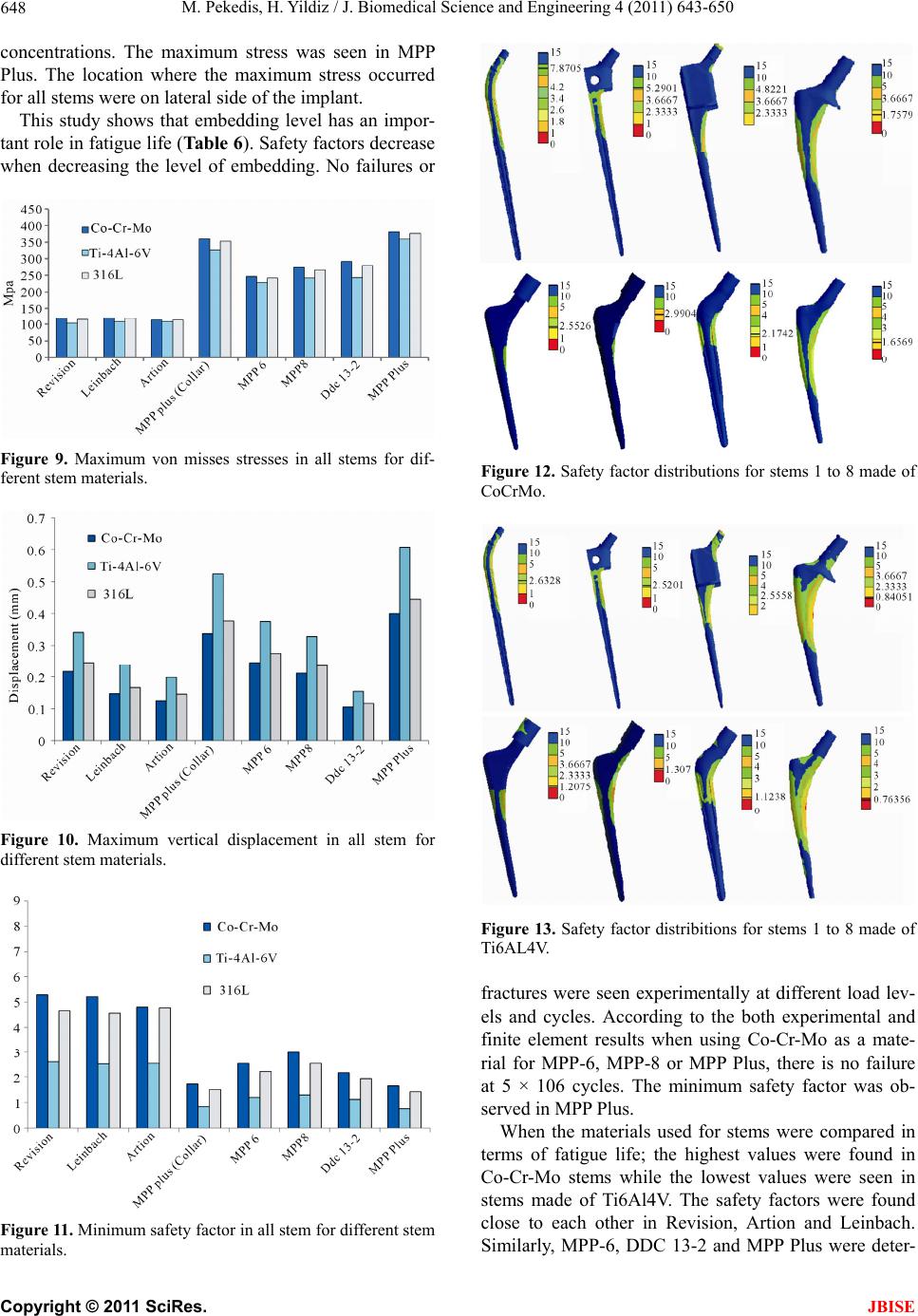
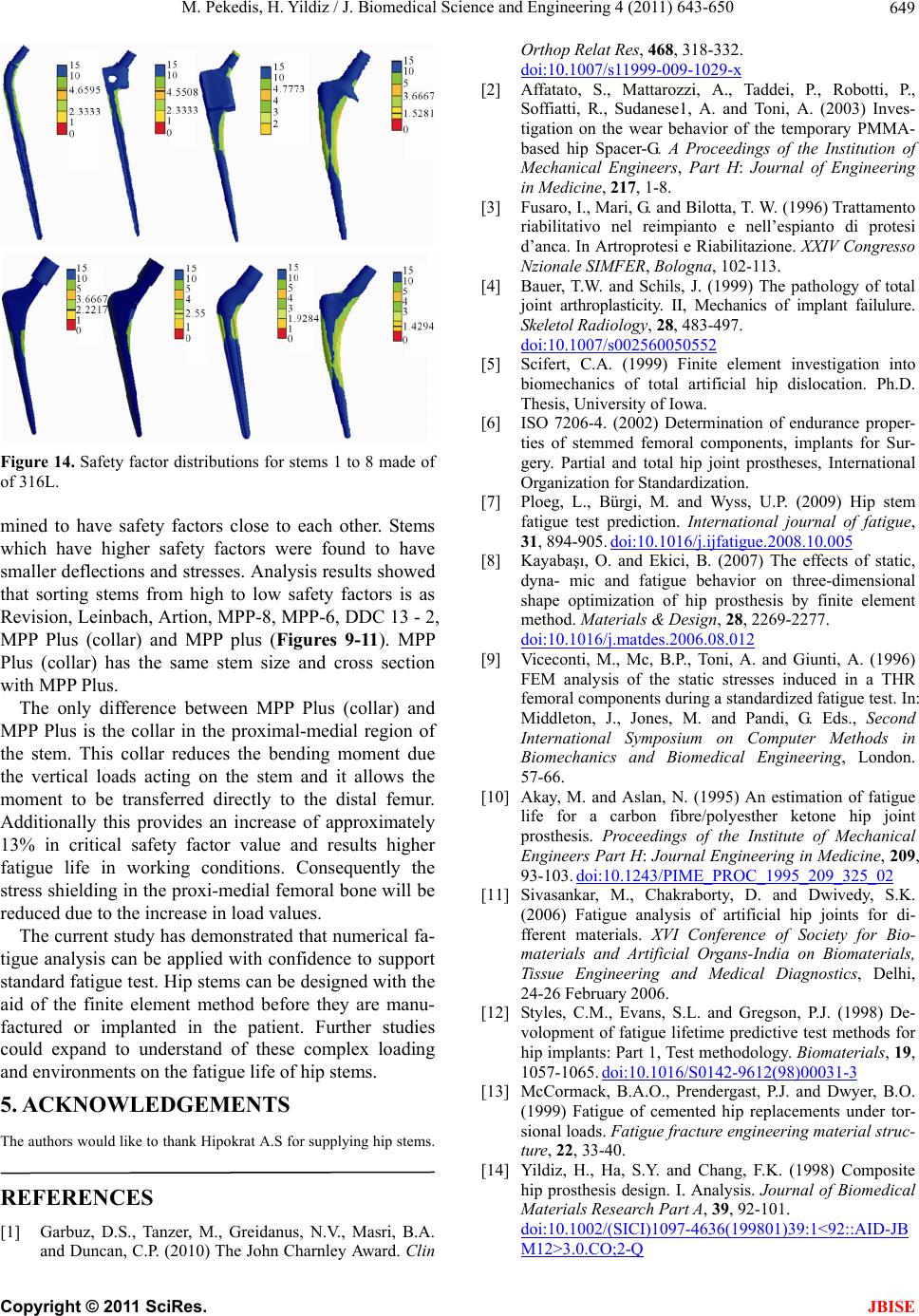
Figure 14. Safety factor distributions for stems 1 to 8 made of
of 316L.
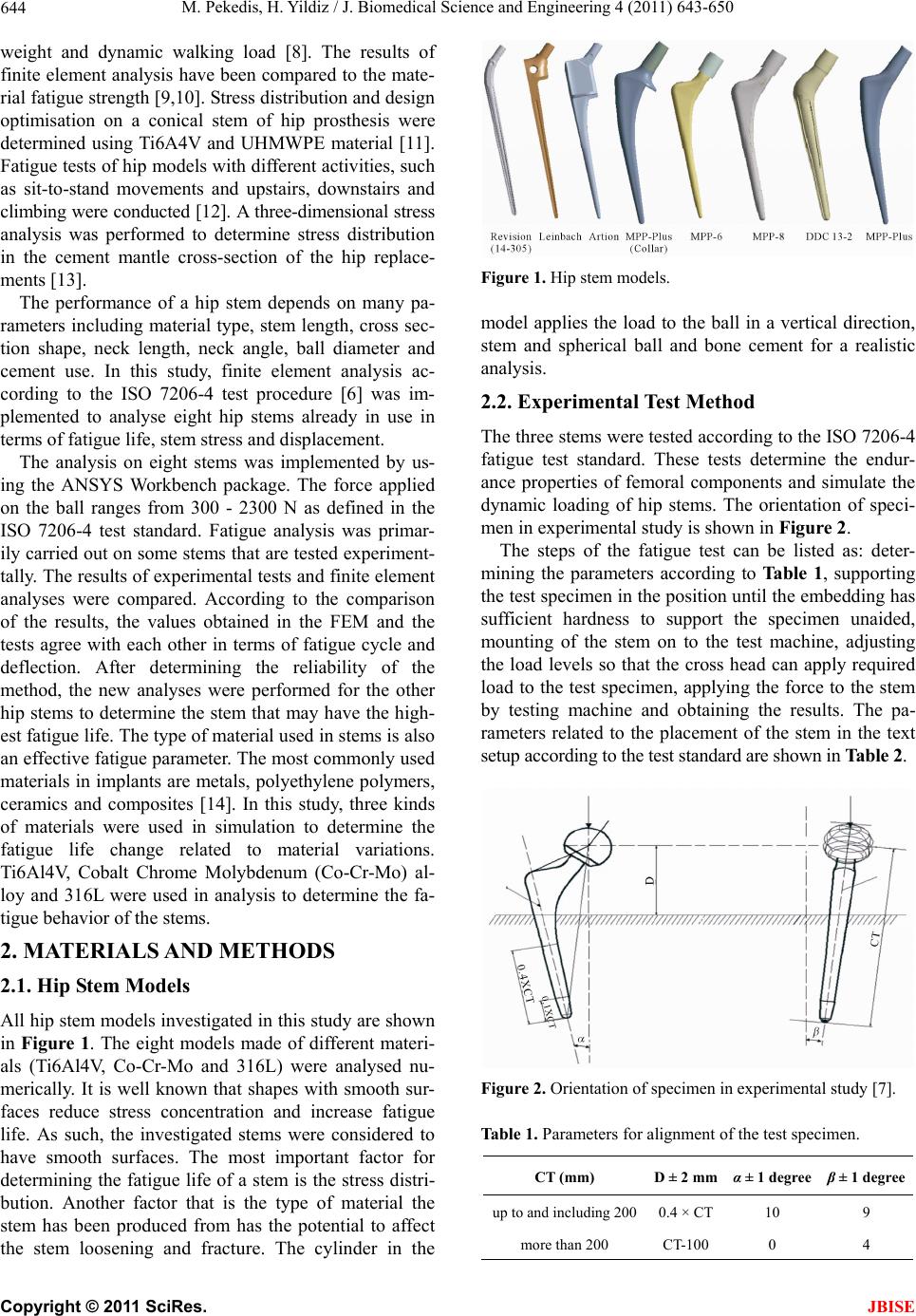
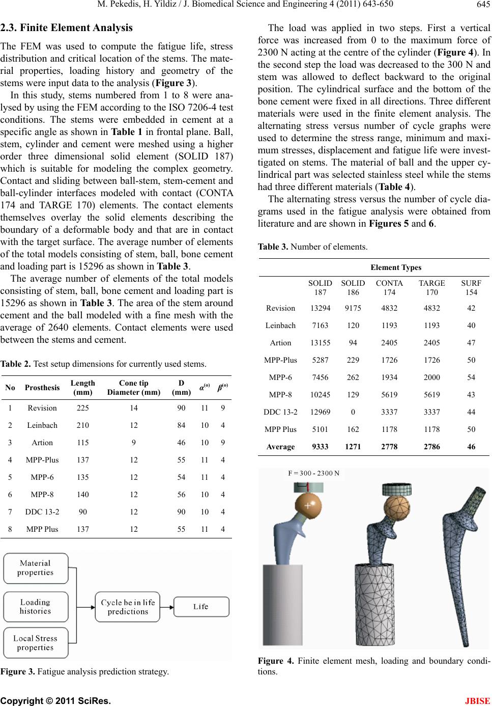
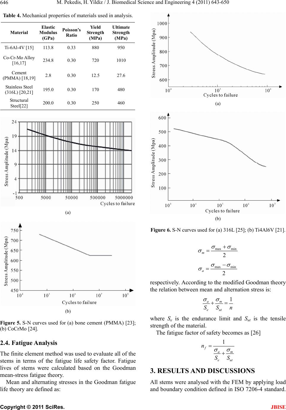
mined to have safety factors close to each other. Stems
which have higher safety factors were found to have
smaller deflections and stresses. Analysis results showed
that sorting stems from high to low safety factors is as
Revision, Leinbach, Artion, MPP-8, MPP-6, DDC 13 - 2,
MPP Plus (collar) and MPP plus (Figures 9-11). MPP
Plus (collar) has the same stem size and cross section
with MPP Plus.
The only difference between MPP Plus (collar) and
MPP Plus is the collar in the proximal-medial region of
the stem. This collar reduces the bending moment due
the vertical loads acting on the stem and it allows the
moment to be transferred directly to the distal femur.
Additionally this provides an increase of approximately
13% in critical safety factor value and results higher
fatigue life in working conditions. Consequently the
stress shielding in the proxi-medial femoral bone will be
reduced due to the increase in load values.
The current study has demonstrated that numerical fa-
tigue analysis can be applied with confidence to support
standard fatigue test. Hip stems can be designed with the
aid of the finite element method before they are manu-
factured or implanted in the patient. Further studies
could expand to understand of these complex loading
and environments on the fatigue life of hip stems.
5. ACKNOWLEDGEMENTS
The authors would like to thank Hipokrat A.S for supplying hip stems.
REFERENCES
[1] Garbuz, D.S., Tanzer, M., Greidanus, N.V., Masri, B.A.
and Duncan, C.P. (2010) The John Charnley Award. Clin
Orthop Relat Res, 468, 318-332.
doi:10.1007/s11999-009-1029-x
[2] Affatato, S., Mattarozzi, A., Taddei, P., Robotti, P.,
Soffiatti, R., Sudanese1, A. and Toni, A. (2003) Inves-
tigation on the wear behavior of the temporary PMMA-
based hip Spacer-G. A Proceedings of the Institution of
Mechanical Engineers, Part H: Journal of Engineering
in Medici ne, 217, 1-8.
[3] Fusaro, I., Mari, G. and Bilotta, T. W. (1996) Trattamento
riabilitativo nel reimpianto e nell’espianto di protesi
d’anca. In Artroprotesi e Riabilitazione. XXIV Congresso
Nzionale SIMFER, Bologna, 102-113.
[4] Bauer, T.W. and Schils, J. (1999) The pathology of total
joint arthroplasticity. II, Mechanics of implant failulure.
Skeletol Radiology, 28, 483-497.
doi:10.1007/s002560050552
[5] Scifert, C.A. (1999) Finite element investigation into
biomechanics of total artificial hip dislocation. Ph.D.
Thesis, University of Iowa.
[6] ISO 7206-4. (2002) Determination of endurance proper-
ties of stemmed femoral components, implants for Sur-
gery. Partial and total hip joint prostheses, International
Organization for Standardization.
[7] Ploeg, L., Bürgi, M. and Wyss, U.P. (2009) Hip stem
fatigue test prediction. International journal of fatigue,
31, 894-905. doi:10.1016/j.ijfatigue.2008.10.005
[8] Kayabaşı, O. and Ekici, B. (2007) The effects of static,
dyna- mic and fatigue behavior on three-dimensional
shape optimization of hip prosthesis by finite element
method. Materials & Design, 28, 2269-2277.
doi:10.1016/j.matdes.2006.08.012
[9] Viceconti, M., Mc, B.P., Toni, A. and Giunti, A. (1996)
FEM analysis of the static stresses induced in a THR
femoral components during a standardized fatigue test. In:
Middleton, J., Jones, M. and Pandi, G. Eds., Second
International Symposium on Computer Methods in
Biomechanics and Biomedical Engineering, London.
57-66.
[10] Akay, M. and Aslan, N. (1995) An estimation of fatigue
life for a carbon fibre/polyesther ketone hip joint
prosthesis. Proceedings of the Institute of Mechanical
Engineers Part H: Journal Engineering in Medicine, 209,
93-103. doi:10.1243/PIME_PROC_1995_209_325_02
[11] Sivasankar, M., Chakraborty, D. and Dwivedy, S.K.
(2006) Fatigue analysis of artificial hip joints for di-
fferent materials. XVI Conference of Society for Bio-
materials and Artificial Organs-India on Biomaterials,
Tissue Engineering and Medical Diagnostics, Delhi,
24-26 February 2006.
[12] Styles, C.M., Evans, S.L. and Gregson, P.J. (1998) De-
volopment of fatigue lifetime predictive test methods for
hip implants: Part 1, Test methodology. Biomaterials, 19,
1057-1065. doi:10.1016/S0142-9612(98)00031-3
[13] McCormack, B.A.O., Prendergast, P.J. and Dwyer, B.O.
(1999) Fatigue of cemented hip replacements under tor-
sional loads. Fatigue fracture engineering material struc-
ture, 22, 33-40.
[14] Yildiz, H., Ha, S.Y. and Chang, F.K. (1998) Composite
hip prosthesis design. I. Analysis. Journal of Biomedical
Materials Research Part A, 39, 92-101.
doi:10.1002/(SICI)1097-4636(199801)39:1<92::AID-JB
M12>3.0.CO;2-Q
C
opyright © 2011 SciRes. JBISE
M. Pekedis, H. Yildiz / J. Biomedical Science and Engineering 4 (2011) 643-650
Copyright © 2011 SciRes.
650
JBISE
[15] Titanium Ti-6Al-4V (Grade 5) (2011) Annealed.
http://asm.matweb.com/search/SpecificMaterial.asp?bass
num=MTP641
[16] Materal Property Date, (2011) Carpenter MP35N* Ni-
Co-Cr-Mo alloy, 25% cold reduction.
http://www.matweb.com/search/DataSheet.aspx?MatGUI
D=b78f5c9066924c5eb6c16d949f27d928
[17] Murray, K., Kearns, M. and Mottu, N. (2009) Alloy
powders for medical applications. Medical Device Te-
chnology, 20, 50-51.
[18] Saha, S., Pal, S. (1984) Mechanical properties of bone
cement. Journal of Biomed Mater Research, 18, 435-462.
doi:10.1002/jbm.820180411
[19] Litchman, H.M., Richman, M.H., Warman, M. and Mit-
chell, J. (1978) Improvement of the mechanical proper-
ties of polymethylmethacrylate by graphite fiber reinfor-
ce-ment. Transaction Orthpadidc Resesrch, 2, 86.
[20] SpecSearch, (2011) AISI type 316L.
http://www.efunda.com/materials/alloys/stainless_steels/s
how_stainless.cfm?ID=AISI_Type_316L&show_prop=al
l&Page_Title=AISI%20Type%20316L
[21] Teoh, S.H. (2000) Fatigue of biomaterials: A review.
International Journal of Fatigue, 22, 825-837.
doi:10.1016/S0142-1123(00)00052-9
[22] ANSYS (2007) Theory reference manual. Release 11.0,
ANSYS Inc.
[23] Pilliar, R.M., Blackwell, R., Macnab, I. and Cameron,
H.U. (1976) Carbon-fiber reinforced bone cement in or-
thopaedic surgery. Journal of Biomedical Materals Re-
sesrch, 10, 893-906. doi:10.1002/jbm.820100608
[24] Bayrak, O., Yetim, A.F., Alsaran, A. and Çelik, A. (2010)
Fatigue life determination of plasma nitrided medical
grade CoCrMo alloy. Materials & Structures, 33, 303-
309.
[25] Taira, M., Lautenschlager, E.P. (1992) In vitro corrosion
fatigue of 316L cold worked stainless steel. Journal of
Biomedical Materals Resesrch, 26, 1131-1139.
doi:10.1002/jbm.820260903
[26] Budynas, R.G., Nisbett, J.K. (2008) Shigley’s mechani-
cal engineering design. 8th Edition, Mc Graw Hill, Bos-
ton.