Circuits and Systems, 2011, 2, 269-273
doi:10.4236/cs.2011.24037 Published Online October 2011 (http://www.scirp.org/journal/cs)
Copyright © 2011 SciRes. CS
A New CMOS Current Controlled Qu adrature O sci llat or
Based on a MCCII
Ashwek Ben Saied1,2, Samir Ben Salem2,3, Dorra Sellami Masmoudi1,2
1Computor Imaging and Electronic Systems Group (CIEL), Research Unit on Intelligent Design
and Control of com pl ex Syst ems (ICOS), Sfax, Tunisia
2University of Sfax, Nation al En gi neeri ng School of Sf ax (ENIS), Sfax, Tunisia
3Development Group in Electronics and Communications (EleCom)
Laborat ory of El ect ron i cs a nd Informati on Technology (LETI), Sfax, Tunisia
E-mail: Achwek.bensaied@ gmail.com, samir.bensalem@isecs.rnu.tn, dorra.ma sm oudi@enis.rn u.tn
Received March 15, 2011; revised April 21, 2011; accepted April 28, 2011
Abstract
In this paper, we propose a design of a current controlled Quadrature Sinusoidal Oscillator. The proposed
circuit employs three optimized Multi-output translinear second generation current conveyer (MCCII). The
oscillation condition and the oscillation frequency are independently controllable. The proposed Quadrature
Oscillator frequency can be tuned in the range of [198 - 261 MHz] by a simple variation of a DC current.
PSpice simulation results are performed using CMOS 0.35 µm process of AMS.
Keywords: Quadrature Sinusoidal Oscillator, Optimized MCCII
1. Introduction
Controlled Quadrature Sinusoidal Oscillator is a basic
signal-generating block frequently needed in communi-
cation systems, instrumentation and control systems. In
communication it is require for Quadrature mixer and
single side band generators.
MCCII based Quadrature oscillator presents a good
solution to avoid limitations of Surface Acoustic Wave,
such as problems of integration, impedance matching,
tuning, linearity, etc.
In order to get controllable characteristics for the pro-
posed Quadrature Qscillator, translinear Multi-output
second generation current controlled conveyer based str-
ucture seems to be the most attractive [1-3]. In fact, be-
ing able to control the output resistance at port X by
means of a current source [4-6], one may exploit this in
the synthesis of electronically adjustable functions [5-8].
Translinear MCCII family is wathly extended to MOS
submicron technologies going towards VLSI design.
Indeed, reaching sub-micron technologies, the MOS
transistor becomes able to achieve high transit frequen-
cies [1,7,9,11]. These Multi-output conveyors are em-
ployed in different RF controllable applications such as
oscillators, quadrature oscillator and filters [1,2,7,11].
In this paper, we are interested in the design of MCCII
based Quadrature Oscillator. This paper is organized as
follows: in section II, we present the MCCII based Qua-
drature oscillator architecture [1]. Then After presenting
the inconvenient of this oscillator, we present the general
characteristics of Multi-output second generation trans-
linear current conveyor in section III. In section IV, we
give the proposed Controlled Quadrature Oscillator. Fi-
nally, the proposed structure is designed and simulated
using PSPICE.
2. The Controlled Quadrature Oscillator
Parven Beg [1] presents a novel single resistance con-
trolled sinusoidal quadrature oscillator shown in Figure
1. This architecture uses only two CMOS multioutput
CCIIs along with the grounded resistors and capacitors.
The corresponding oscillation condition is given by:
2
1221223
1111 0ss
RRCCCRR




2
(1)
It leads to the following condition
1
RR
(2)
and following oscillation frequency:
A. B. SAIED ET AL.
270
R
1
R
2
R
4
R
3
R
5
C
2
C
1
V
O2
V
O1
YY
X
X
Z
MOCCll MO C C ll
Z
Z
Z
Z
Figure 1. Quadrature oscillator implementation proposed
by Parven Beg.
0
1232
1
2
fCCRR
(3)
From Equation (3), we get a variable frequency oscil-
lator. The oscillation frequency can be adjusted indepen-
dently without modification of the oscillation condition
by varying R3 [1]. However, to avoid tuning R3 after in-
tegration, one can change this external resistance by an
internal active controllable one corresponding to the X
port parasitic resistance of the MCCII.
CMOS Implementation of the MCCII
The MCCII can be represented by the symbol of Figure
2. The port relations of the MCCII can be characterized
by the following expression:
0, ,
YXYXXZiX
I
VVIRI I
  and
Z
iX
I
I
where, RX denote the parasitic resistance at the X input
terminal of the MCCII and i = 1, 2, 3. The plus and mi-
nus sign of the current transfer ratio represent the posi-
tive and negative types of the MCCII outputs
The terminal characteristic of the MCCII can be de-
scribed by the following matrix equation:
1
2
3
1
2
3
000
100
010
010
010
010
010
010
Y
X
ZY
ZX
ZZ
Z
Z
Z
I
V
IV
I
I
IV
I
I
I








 

 

 

 












(4)
The MCCII implementation is given in Figure 3. As-
suming the same gain factors for both NMOS and PMOS
transistors, the parasitic impedances are described by the
following expressions (5)

1
*
oNP
Ry I (6)


11,,3or 1,,3
*

 

oNP
Rzi i
I (7)
2
We notice that the optimization process can be done in
the same way for other simulation conditions [7,9,10].
Table 1 shows the optimal device scaling that we get
after applying the optimization approach.
Figure 4 shows the simulated parasitic resistance at
port X (RX) in the optimized configuration. It can be
tuned on more than a decade over [427 , 7.1 k] by
varying Io in the range [1 μA - 400 μA]. Such control is
very important, since it will be used to replace the resis-
tance R3 in the Quadrature Oscillator giving in Figure 3.
Figure 4 depicts results obtained from both PSPICE
software simulations (RX) and MAPLE theoretical calcu-
lus of (RXthe). We Notice a global agreement between
both characteristics.
3. Proposed Oscillator
The basic idea in the improved structure consists on re-
placing the resistance R3 by the parasitic resistance on
port X. We then use this implementation of MCCII, pre-
senting a variable resistance on port X. The Quadrature
oscillator, will be in that case controlled by means of the
bias current Io in the MCCII3.
The proposed Quadrature Sinusoidal Oscillator is pre-
sented in Figure 5. The modified oscillation condition
and oscillation frequency are respectively given by the
following expressions:
1
RR
(8)
0
12 32
1
2X
fCCRR
(9)
From Equation (9), we get a variable frequency oscil-
lator. In fact, the oscillation frequency can be adjusted
independently without modification of the oscillation
condition by varying RX3 (by varying Io3 current of the
MCCII3). The proposed Quadrature oscillator is simu-
lated for different MCCII3 bias currents. Simulation re-
sults are shown in Figure 6. When varying the control
current between 10 μA and 400 μA, the oscillation fre-
quency is tuned in the range [198 MHz - 261MHz].
 
1
*2121


 
 

 
 


oNNDS PPDS
NXX PXX
Rx WW
IKV KV
LL
(5)
Copyright © 2011 SciRes. CS
A. B. SAIED ET AL.271
MCCII
X
Y
Z1+
Z2+ Z3+
Z3-
Z2-
Z1-
Io
Figure 2. MCCII block.
Figure 3. MCCII implementation using translinear loop Io.
Figure 4. Parasitic resistance at port X versus the control current Io ( Rxthe, ---RX).
Figure 5. The proposed quadrature oscillator implementation.
Copyright © 2011 SciRes. CS
A. B. SAIED ET AL.
272
Figure 6. Oscillation frequency versus control current.
Table 1. Device scaling after optimisation process
Device Name Aspect ratio W/L
M1, M2 12/0.35 (µm)
M3, M4 36/0.35 (µm)
Mxx (in PMOS current mirrors) 18/0.35 (µm)
Mxx (in NMOS current mirrors) 6/0.35 (µm)
The circuit was simulated using R1 = R2 = R4 = 500
R5 = 1 K, RX3 = 450 
3 = 100 µA), C1 = C2 = 0.2 pF
and Io1 = Io2 = 100 μA. The obtained oscillation fre-
quency is 225 MHz and the obtained quadrature voltage
waveforms are shown in Figure 7. Simulations were
carried out using 0.35 μm CMOS process parameters.
ime
10.000us 10.002us 10.004us 10.006us 10.008us 10.010us 10.012us 10.014us 10.016us 10.018us10.020us
V(C1:2) V(U22:Z3+)
-2.0V
-1.0V
0V
1.0V
2.0V
V
c1
V
c2
Figure 7. The simulated of Quadrature output waveforms.
Copyright © 2011 SciRes. CS
A. B. SAIED ET AL.273
4. Conclusions
In this paper, we have proposed a new design of variable
frequency current controlled Quadrature oscillators. In
order to get high frequency performances of the oscilla-
tor, we use an optimized translinear multi-output CCII
structure in 0.35 m CMOS process of AMS. Simulation
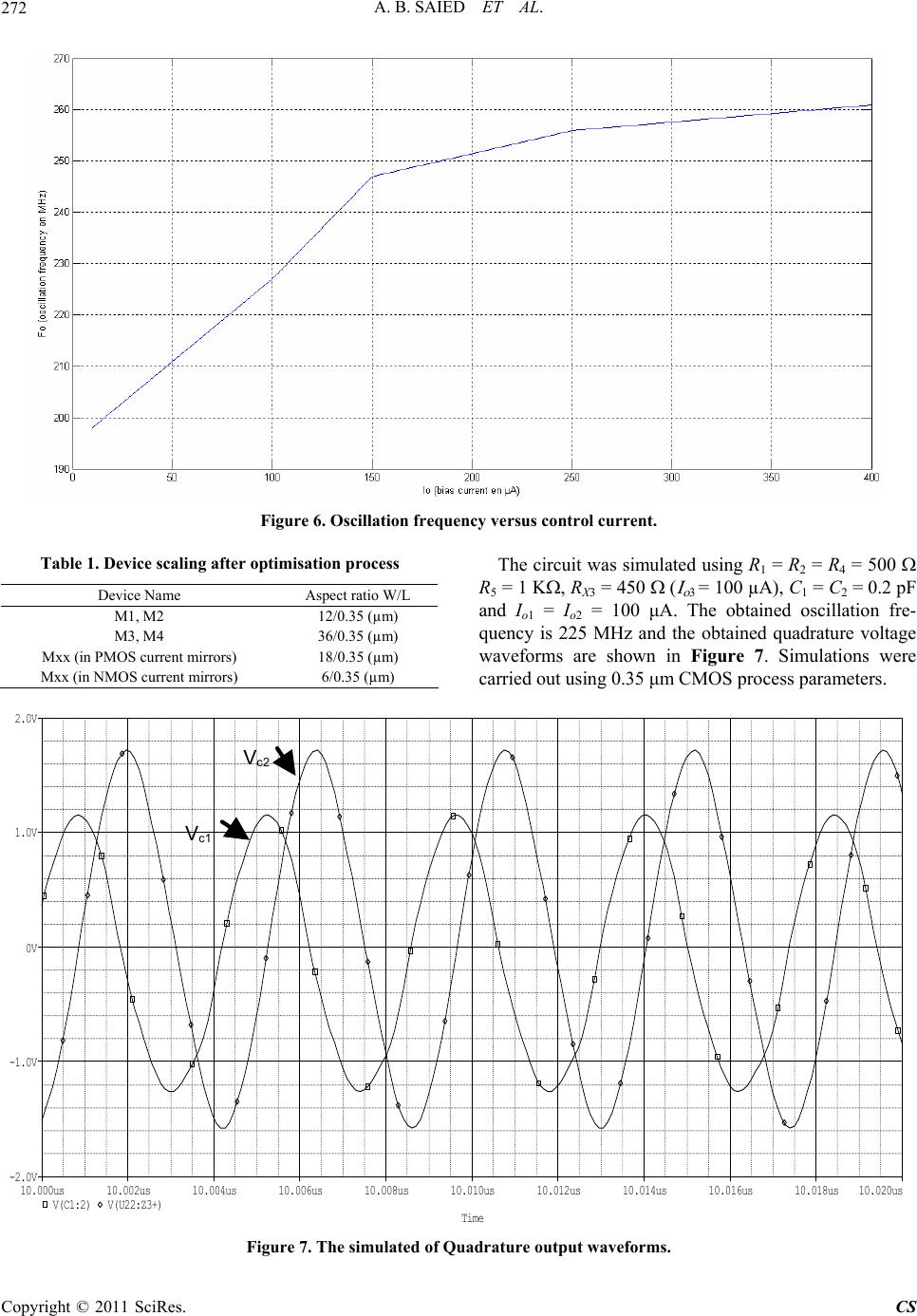
results show that this Quadrature oscillator provides a
control of the oscillation frequency which is independent
from the oscillation condition in the range [198 MHz -
261 MHz] by varying the control current in the range [10
µA - 400 µA].
5. References
[1] P. Beg, I. A. Khan and M. T. Ahmed, “Tunable Four
Phase Voltage Mode Quadrature Oscillator Using Two
CMOS MOCCIIs,” Multimedia, Signal Processing and
Communication Technologies, Aligarh, 14-16 March 2009,
pp. 155-157. doi:10.1109/MSPCT.2009.5164198
[2] S. Maheshwari, “Quadrature Oscillator Using Grounded
Components with Current and Voltage Outputs,” IET
Circuits, Devices & Systems, Vol. 3, No. 4, 2009, pp.
153-160. doi:10.1049/iet-cds.2009.0072
[3] S. Maheshwari, “Analogue Signal Processing Applica-
tions Using a New Circuit Topology,” IET Circuits, De-
vices & Systems, Vol. 3, No. 3, 2008, pp. 106-115.
doi:10.1049/iet-cds.2008.0294
[4] A. Fabre, O. Saiid, F. Wiest and C. Bouchern, “High Fre-
quency High-Q BICMOS Current-Mode Bandpass Filter
and Mobile Communication Application,” IEEE Transac-
tion on Circuits and Systems 1: Fundamental Theory and
Applications, Vol. 33, No. 4, 1998, pp. 614-625.
doi:10.1109/4.663567
[5] H. O. Elwan and A. M. Soliman, “Low-Voltage Low-
Power CMOS Current Conveyors,” IEEE Transaction on
Circuits and Systems 1: Fundamental Theory and Appli-
cations, Vol. 44, No. 9, 1997, pp. 828-835.
doi:10.1109/81.622987
[6] D. S. Masmoudi, S. Ben Salem, M. Loulou, L. Kammoun
“A Radio Frequency CMOS Current Controlled Oscilla-
tor Based on a New Low Parasitic Resistance CCII,”
2004 International Conference on Electrical, Electronic
and Computer Engineering, Egypt, 5-7 September 2004,
pp. 563-566. doi:10.1109/ICEEC.2004.1374532
[7] S. B. Salem, M. Fakhfakh, D. S. Masmoudi, M. Loulou,
P. Loumeau and N. Masmoudi, “A High Performances
CMOS CCII and High Frequency Applications,” Journal
of Analog Integrated Circuits and Signal Processing, Vol.
49, No. 1, 2006, pp. 71-78.
doi:10.1007/s10470-006-8694-4
[8] S. B. Salem, D. S. Masmoudi and M. Loulou “A Novel
CCII-Based Tunable Inductance and High Frequency Cu-
rrent Mode Band Pass Filter Application,” Journal of
Circuits, Systems, and Computers (JCSC), Vol. 15, No. 6,
2006, pp. 849-860.
[9] S. B. Salem, D. S. Masmoudi, A. B. Saied and M. Loulou
“An Optimized Low Voltage and High Frequency CCII
Based Multifunction Filters,” 13th IEEE International
Conference on Electronics, Circuits and Systems, Nice,
10-13 December 2006, pp. 1268-1271.
doi:10.1109/ICECS.2006.379693
[10] A. B. Saied, S. B. Salem, M. Fkih and D. S. Masmoudi
“A New High Frequency Second Generation Current
Conveyor Based Chaos Generator,” 14th IEEE Interna-
tional Conference on Electronics, Circuits and Systems,
Marrakech, 11-14 December 2007, pp. 387-390.
doi:10.1109/ICECS.2007.4511011
[11] C. Thoumazou, F. J. Lidgey and D. Haigh, “Integrated
Circuits: The Current Mode Approach,” IEEE Circuit
and Systems Series 2, Peter Ltd., London, 1993.
Copyright © 2011 SciRes. CS