International Journal of Communications, Network and System Sciences
Vol.10 No.08(2017), Article ID:78400,10 pages
10.4236/ijcns.2017.108B025
Design of Dynamic Reconfigurable Structure Based on Integrated Filter Banks
Wenxu Zhang, Chengqun Zhou, Zheng Dou
College of Information and Communication Engineering, Harbin Engineer University, Harbin, China


Received: May 15, 2017; Accepted: August 11, 2017; Published: August 14, 2017
ABSTRACT
In electronic confrontation, radar confrontation is an important part. Various radars widely used in modern warfare are the most important equipment in the field of information acquisition and precision guidance. Especially in the vast battle space, in order to achieve timely, accurate and comprehensive access to various target information, the role of radar is irreplaceable. Especially in the vast battle space, the role of radar is irreplaceable in order to achieve timely, accurate and comprehensive access to various target information. Therefore, in the war, it will not be able to protect their own survival and play combat effectiveness if not having the radar's ability to fight. At this time, that is the need for radar equipment in time to detect radar exposure, rapid measurement of radar signal parameters and identify threat signals, and targeted to do the implementation of interference or the implementation of technical attacks. In order to extract the parameters of the received signal to facilitate the subsequent research and analysis, this paper deduces the structure of the integrated filter bank in detail, and gives the reconfigurable filter bank structure design method, under the condition of accurate reconstruction of the signal. Based on the analysis of the design and calculation complexity of the filter bank structure, the dynamic reconfigurable design method consumes less hardware resources and wide application range, and the simulation structure also verifies the correctness and flexibility of the structure.
Keywords:
Integrated Filter Banks, Dynamic Reconfigurbale, Computational Complexity

1. Introduction
The current digital signal processing technology has developed rapidly, broadband signals are increasingly widely used in modern radar, communications and other electronic equipment. Most of the broadband using digital channelization technology divides the wide instantaneous bandwidth into multiple narrowband channels to process, that makes the input broadband signal into the adjacent multiple channel, that is cross-channel problems [1]. The reconstruction of output under the cross-channel signal without distortion has become a very important issue to facilitate the follow-up signal processing.
Channel reconstruction based on channelization structure mainly includes channelized reception and transmission, the traditional channelization structure can be effectively applied to narrowband signal reconstruction, but for cross- channel reconstruction there is a large degree of distortion [2]. In this paper, a dynamic channelization reconfigurable structure is proposed. Although the improved method is slightly more complicated in design time, the hardware resource consumption is less and the most important is the small degree of reconstruction distortion. When the number of channel processing is small and the amplitude distortion is not strictly considered, the advantage of composite structure based on DFT is obvious, and the dynamic reconfigurable method design has obvious advantages when the number of processing channels is large [3].
2. Theory of Signal Reconstruction
Using the analysis filter group to divide the signal band is the first part of the reconstruction of the broadband signal. The current modulation filter banks include cosine modulation and complex exponential modulation. Cosine modultion can be regarded as a special kind of complex exponential modulation that includes the odd arrangement and even type in the band structure mainly [4]. Therefore, this paper focuses on complex exponential modulation and even arrangement. It is necessary to divide the channel uniformly to reconstruct the wideband signal using the complex exponential modulation filter bank. This part is the analysis filter group, and the analysis filter group decelerates the sampling rate of the input signal, and obtains a plurality of the subband channel is uniformly divided, and the channels belonging to the same wideband signal are merged, that is the integrated filter banks, and the integrated filter banks combine the multiple channels so that the sampling rate of the output signal is improved [5].
“Figure 1” shows the block diagram of the analysis filter banks and the integrated filter bank based on the signal reconstruction theory. The entire channel is evenly divided into K sub-band channels, mixed with the input signal using the complex exponential modulation factor , to move the input signal to the baseband and use a low-pass filter to achieve filtering to eliminate aliasing.
  is the low-pass filter of the analysis filter bank section,
  is the low-pass filter of the integrated filter bank section, and the frequency band of the sub-band channel is limited to
 . The broad- band signal can be divided into K sub-band channels for parallel processing, extracting the sub-band channel signal with D-times, the signal still does not exist aliasing [6]. In the integrated filter bank section, multiple sub-band channel
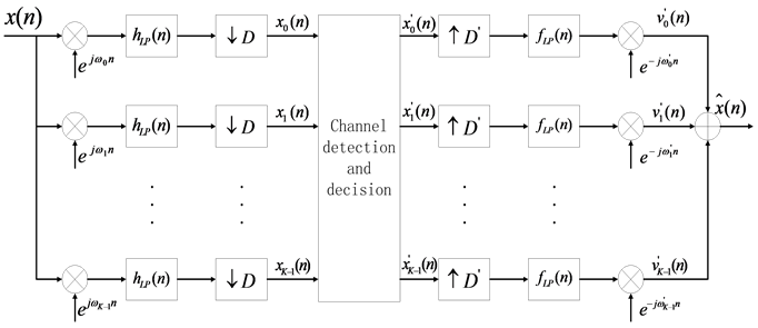
Figure 1. Schematic diagram of the filter bank and the integrated filter bank.
signals can be combined using times interpolation, low-pass filtering, and complex exponential modulation. In order to avoid aliasing, the frequency domain of the sub-band channel of the analysis filter banks should be 0 outside the range , the satisfaction of this condition depends on the low-pass filter
 ’s design included the analysis filter banks [7]. Channel detection and discrimination determine the subband channel covered by the wideband signal, and the signal channel through the integrated filter group reconstructs the original signal [8].
3. Structural Design of Integrated Filter Banks Based on DFT
In the structural part of the integrated parts, the filter frequency of the m-th channel is expressed as:
 (1)
(1)
In Equation (1): ,
, .
.
 (2)
(2)
 is the multiphase component of
 , and P is the smallest integer greater than
 . From Equation (2), we can see that
  can be expressed by IFFT inverse Fourier transform.
Based on the integrated filter structure, the K-times up-sampling module is moved to the band-pass filter bank, then the filter frequency response of the m- th channel is expressed as:
 (3)
(3)
According to Equation (3), the non-maximum decimation filter bank structure is organized into the filter bank structure as shown in “Figure 2”
In the actual engineering application, the number of channels is often an integer power of 2, then the efficient structure of the IDFT module is replaced by IFFT module, which improves the operation rate. As the up-sampling will cause the system sampling rate and data processing rate multiplied, which can be
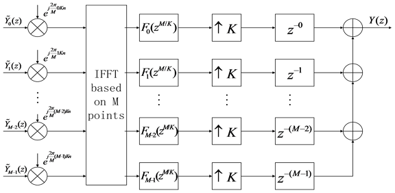
Figure 2. Composite filter bank structure based on DFT.
clearly observed in the integrated filter bank efficient structure based on DFT, the structure of the sampling module will be placed at the end of the system, this can ensure that the entire system has a lower sampling rate to speed up the data processing rate. The efficient structure push forward traditional system to a wider applicability of the non-largest extraction system, whose the prototype filter design is simple, and in the same constraints, that can reduce the amount of computing and hardware resource loss [9] [10] [11].
4. Design of Dynamic Reconfigurable Structural
Assume that the signal is output by the analysis filter bank to occupy the signal number  total
total  signal, where
  satisfies:
 (4)
(4)
To use the IFFT module to ensure the calculation of the speed, the number of integrated channels is defined as M. When P is an even number, the signal inputs from the 0th channel to the integrated part; when P is an odd number, the signal inputs to the integrated part from the first channel. The k-th integrated output signal can be expressed as:
 (5)
(5)
Among Equation (5),  ,
,  represents the remainder. Due to
 (6)
(6)
Then  can be written as:
 (7)
(7)
Since  is even, the Equation (24) at the critical value
  can be decomposed into two parts, then the k-th integrated output
  can be sorted as:
 (8)
(8)
In Equation (8), the first half is a useful signal and the second half is the signal to be cleared. Thus, even if the conditions for precise reconstruction are met, the input signal cannot be fully integrated because the aliasing signal caused by interpolation cannot be eliminated and can only be minimized.
Assume that A is an integer power of 2 associated with B, expressed as:
 (9)
(9)
Therefore, the combined partial output signal  may have a multiple of
 , and no aliasing occurs. The upper sampling multiple I can be converted as shown in “Figure 3” using the integer multiple interpolation theory.
In summary, the definition of , for a combination of a signal filter bank to improve the structure, as shown in “Figure 4”.
The integrated filter bank in “Figure 4” satisfies:
 (10)
(10)
Similarly, when synthesizing multiple signals, the channel number of each signal distribution is determined by analyzing the filter bank section, using the improved structure of “Figure 4”.
When the baseband signal is used as the input of the integrated filter bank, the
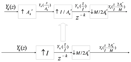
Figure 3. Equivalent transformation of the extractor.
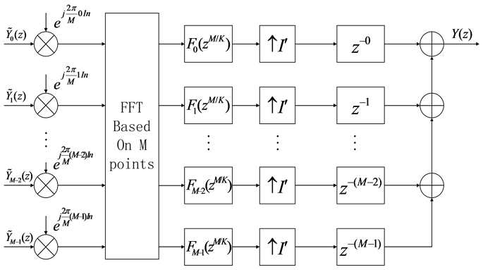
Figure 4. A signal synthesis filter bank to improve the structure.
composite filter bank structure based on DTF is a special case of dynamic reconfigurable and efficient structure design method. In summary, the dynamic reconfigurable structure is superior to the multiphase composite filter bank structure, and is less suitable for engineering than the hardware resource of the integrated filter bank structure based on DFT. However, the amplitude error is not required, if the number of channels in the case of less, based on the DFT integrated filter bank efficient structure advantage is more obvious.
5. Matlab Simulation
5.1. Integrated Filter Banks Structure Simulation
In the design of the filter, the corrugated optimization design can meet the conditions of the attenuation of the stop-band to achieve the minimum filter order, so that there is the use of equal ripple optimization algorithm to design the prototype filter. Set the prototype filter to FIR filter, the filter order as follows: N = 256, the pass-band frequency is 30 MHz, the stop-band frequency is filter order as follows: N = 256, the pass-band frequency is 30 MHz, the stop-band frequency is 40 MHz. Set the prototype filter to FIR filter, the filter order is N = 256, the pass-band frequency is 30 MHz, the stop-band frequency is 40 MHz that uses the critical extraction conditions. Filter magnitude and frequency characteristics, as shown in “Figure 5”, optimized prototype as shown in “Figure 6”.
5.2. Dynamic Reconfigurable Structure Simulation
The input terminals input with two linear FM signals (LFM1, LFM2), and the input signal parameters are shown in “Table 1”. The input signal spectrum is shown in “Figure 7” and “Figure 8”.
The filter design uses non-maximized extraction conditions, the channel is divided into 16 sub-channels, and the lower sampling factor K = 8. The filter de

Figure 5. Filter magnitude and frequency characteristics.

Figure 6. Optimized prototype filters.
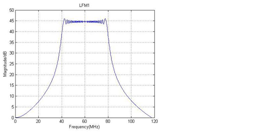
Figure 7. Input signal LFM1 frequency domain waveform.
sign uses non-maximized extraction conditions, the channel is divided into 16-channels, and the lower sampling factor K = 8. When the dynamic reconfigurable structure is used for the simulation, the number of integrated input channels of the signal LFM1 is 2 and the signal LFM2 is outputted over four channels. Then , the number of channels
  of the integrated part inputs to ensure the fast calculation of the IFFT module. According to the theoretical analysis, the integrated filter group coefficients of the signal LFM1 are in turn the value of the proto type filter coefficients
 , and the integrated filter group coefficients of the signal LFM2 are
 .
.
The spectra of the integrated signals LFM1 and LFM2 are shown in “Figure 9” and “Figure 10”, respectively.
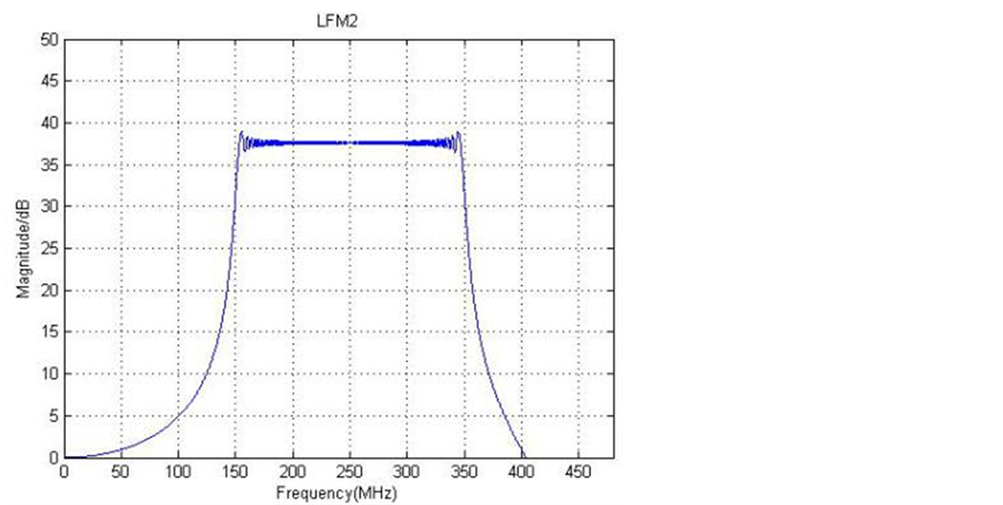
Figure 8. Input signal LFM2 frequency domain waveform.

Table 1. Settings of input signal parameter.
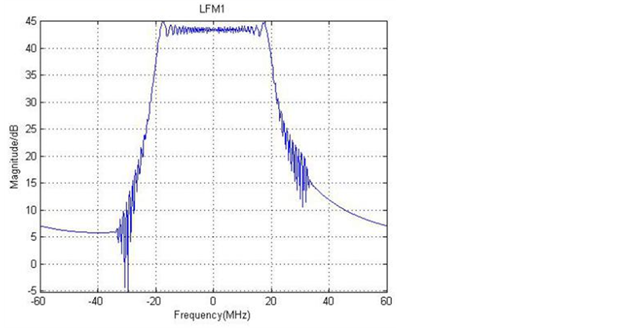
Figure 9. Signal LFM1 integrated spectrum.
5.3. Structural Simulation Analysis
Under the same conditions of the prototype filter design and the input signal, the composite structure simulation proves that the reconstruction effect is better in the case of non-maximized extraction, and the amplitude error is smaller than
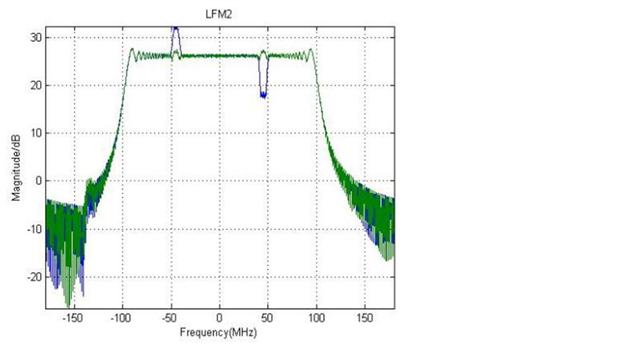
Figure 10. Signal LFM2 Integrated Spectrum.
that of the critical extraction.
“Figure 9” shows the integrated spectral waveform of the signal LFM1. The signal LFM1 does not cross the channel and the spectral waveform does not appear. The glitches are generated on both sides as compared with the spectral waveform of the original input signal. This is due to the phase distortion.
“Figure 10” shows the integrated spectrum of the signal LFM2. After analysis, it can be seen that the signal LFM2 is the least reconstructed in the multi-phase composite structure because the structure is simulated under critical extraction conditions. Signal LFM2 cross-channel output, so there will be a transition process during the refactoring process. Among them, the convex phenomenon is obvious in the multi-phase comprehensive structure, but the convex phenomenon will be significantly weakened when the order of prototype filter’s design tends to infinity, and that even cannot be observed.
In summary, the dynamic reconfigurable synthesis filter bank structure design method, although the design process is more complex, the reconstruction error is small, and the hardware resource consumption is also small, and the dynamic reconfigurable design method has obvious advantages when the number of channels is large.
6. Conclusion
It is shown that the structure of dynamic reconfigurable composite filter banks have obvious advantages under the condition of limited multiplier resource, and the structure of integrated filter bank based on DFT is a special case. The result of MATLAB simulation proves the flexibility and accuracy of the reconfigurable synthesis filter banks. It can be seen that the aliasing effect between channels cannot be completely eliminated due to the existence of the filter transition band.
Acknowledgements
This paper is funded by the International Exchange Program of Harbin Engineering University for Innovation-oriented Talents. This work is supported partly by National Natural Science Foundation of China under Grant No. 61301205 and No. 61571146, National Defense Based Science Research Program under Grant No. JCKY2013604B001.
Cite this paper
Zhang, W.X., Zhou, C.Q. and Dou, Z. (2017) Design of Dynamic Reconfigurable Structure Based on Integrated Filter Banks. Int. J. Communications, Network and System Sciences, 10, 236-245. https://doi.org/10.4236/ijcns.2017.108B025
References
- 1. Zhu, X. and Si, X.C. (2009) An Efficient Dynamic Digital Channelization Method. Journal of Harbin Institute of Technology, 41, 160-164.
- 2. Gao, X.-G. and Zuo, Y. (2015) A Wideband Signal Reconstruction Method with Improved Channel Structure. Electronic Information Confrontation Technology, 30, 63-67.
- 3. Zakaria, R. and Le Ruyet, D. (2012) A Novel Filter-Bank Multicarrier Scheme to Mitigate the Intrinsic Interference: Application to MIMO Systems. IEEE Transactions on Wireless Communications, 11, 2506-2517. https://doi.org/10.1109/TWC.2012.012412.110607
- 4. Roldan, F.C., Lopez, P.A., Bascon, S.M. and Lawson, S.S. (2002) An Efficient and Simple Method for Designing Prototype Filters for Cosine-Modulated Pseudo-QMF Banks. IEEE Signal Pro-cessing Letters, 9, 29-31. https://doi.org/10.1109/97.988722
- 5. Cruz Pedro, M. and Nuno, B.C. (2011) Wideband Be-havioral Model for Nonlinear Operation of Bandpass Sampling Receivers. IEEE Transactions on Microwave Theory and Techniques, 59, 1006-1015. https://doi.org/10.1109/TMTT.2010.2100406
- 6. Kiran, G. and Chen, C.-I.H. (2011) A Hybrid Computing Platform Digital Wideband Receiver Design and Performance Measurement. IEEE Transactions on Instrumentation and Measure-ment, 60, 3956-3958. https://doi.org/10.1109/TIM.2011.2152590
- 7. Tang, H., Zhao, C.H. and Zhang, C.Z. (2006) Design of Channel Receiver Based on Multiphase Filter Group. The Application of Science and Technology, 6, 0008-0003.
- 8. Chen, T., Wang, Y. and Liu, Y. (2015) Lowed Transition Channel Channelized Receiver Based on Frequency Response Shielding. Journal of Jilin University, 45, 335- 340.
- 9. Zhang, W.X. (2009) Research and Implementation of Digital Radar Receiver for Passive Radar Seeker. Harbin Engineering University, Harbin.
- 10. Romero, D.E.T. (2015) High-Speed Multiplierless Frequency Response Masking (FRM) FIR Filters with Reduced Usage of Hardware Resources. Midwest Symposium on Circuits and Sys-tems, 1-4. https://doi.org/10.1109/MWSCAS.2015.7282049
- 11. Wu, F.Z. and Villing, R. (2016) FPGA Based FRM GDFT Filter Banks. Irish Signals and Systems Conference, 1-6. https://doi.org/10.1109/ISSC.2016.7528473