Paper Menu >>
Journal Menu >>
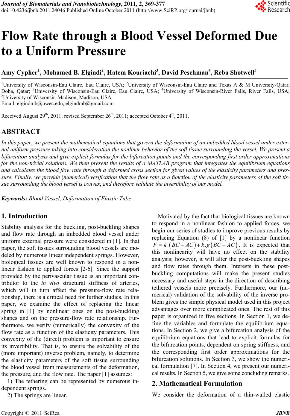 Journal of Biomaterials and Nanobiotechnology, 2011, 2, 369-377 doi:10.4236/jbnb.2011.24046 Published Online October 2011 (http://www.SciRP.org/journal/jbnb) Copyright © 2011 SciRes. JBNB 369 Flow Rate through a Blood Vessel Deformed Due to a Uniform Pressure Amy Cypher1, Mohamed B. Elgindi2, Hatem Kouriachi3, David Peschman4, Reba Shotwell5 1University of Wisconsin-Eau Claire, Eau Claire, USA; 2University of Wisconsin-Eau Claire and Texas A & M University-Qatar, Doha, Qatar; 3University of Wisconsin-Eau Claire, Eau Claire, USA; 4University of Wisconsin-River Falls, River Falls, USA; 5University of Wisconsin-Madison, Madison, USA. Email: elgindmb@uwec.edu, elgindmb@gmail.com Received August 29th, 2011; revised September 26th, 2011; accepted October 4th, 2011. ABSTRACT In this paper, we present the mathematical equations that govern the deformation of an imbedded blood vessel under exter- nal uniform pressure taking into consideration the nonliner behavior of th e soft tissue surrounding the vessel. We presen t a bifurcation analysis and give explicit formulas for the bifurcation points and the corresponding first order approximations for the non-trivial solutions. We then present the results of a MATLAB program that integrates the equilibrium equations and calculates the blood flow rate through a deformed cross section for given values of the elasticity parameters and pres- sure. Finally, we provide (numerical) verification that the flow rate as a function of the elasticity parameters of the soft tis- sue surrounding the blood vessel is convex, and theref ore validate the invertibility of our model. Keywords: Blood Vessel, Deformation of Elastic Tube 1. Introduction Stability analysis for the buckling, post-buckling shapes and flow rate through an imbedded blood vessel under uniform external pressure were considered in [1]. In that paper, the soft tissues surrounding blood vessels are mo- deled by numerous linear independent springs. However, biological tissues are well known to respond in a non- linear fashion to applied forces [2-6]. Since the support provided by the perivascular tissue is an important con- tributor to the in vivo structural stiffness of arteries, which will in turn affect the pressure-flow rate rela- tionship, there is a critical need for further studies. In this paper, we examine the effect of replacing the linear spring in [1] by nonlinear ones on the post-buckling shapes and on the pressure-flow rate relationship. Fur- thermore, we verify (numerically) the convexity of the flow rate as a function of the elasticity parameters. This convexity of the (direct) problem is important to ensure its invertibility. That is, to ensure the solvability of the (more important) inverse problem, namely, to determine the elasticity parameters of the soft tissue surrounding the blood vessel from measurements of the deformation, the pressure, and the flow rate. The paper [1] assumes: 1) The tethering can be represented by numerous in- dependent springs. 2) The springs are linear. Motivated by the fact that biological tissues are known to respond in a nonlinear fashion to applied forces, we begin our series of studies to improve previous results by replacing Equation (8) of [1] by a nonlinear function 12 = F kBCAC kgBCAC . It is expected that this nonlinearity will have no effect on the stability analysis; however, it will alter the post-buckling shapes and flow rates through them. Interests in these post- buckling computations will make the present studies necessary and useful steps in the direction of describing tethered vessels more precisely. Furthermore, our (nu- merical) validation of the solvability of the inverse pro- blem gives the simple physical model used in this project advantages over more complicated ones. The rest of this paper is organized in five sections. In Section 1, we de- fine the variables and formulate the equilibrium equa- tions. In Section 2, we give a bifurcation analysis of the equilibrium equations that lead to explicit formulas for the bifurcation points, dependent on spring stiffness, and the corresponding first order approximations for the bifurcation solutions. In Section 3, we show the numeri- cal formulation [7]. In Section 4, we present our numeri- cal results. In Section 5, we give some concluding remarks. 2. Mathematical Formulation We consider the deformation of a thin-walled elastic 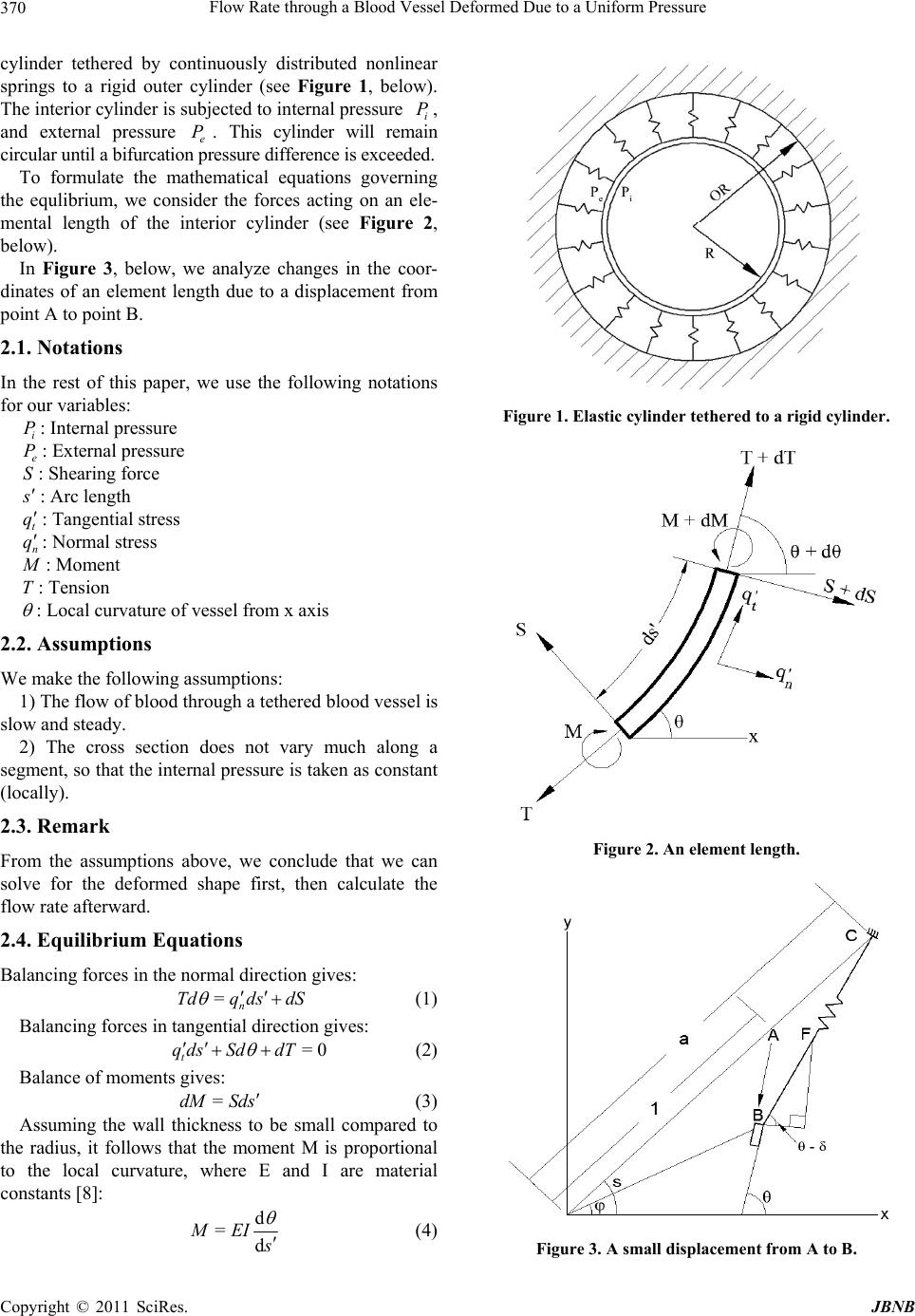 Flow Rate through a Blood Vessel Deformed Due to a Uniform Pressure 370 cylinder tethered by continuously distributed nonlinear springs to a rigid outer cylinder (see Figure 1, below). The interior cylinder is subjected to internal pressure i, and external pressure e. This cylinder will remain circular until a bifurcation pressure difference is exceeded. P P To formulate the mathematical equations governing the equlibrium, we consider the forces acting on an ele- mental length of the interior cylinder (see Figure 2, below). In Figure 3, below, we analyze changes in the coor- dinates of an element length due to a displacement from point A to point B. 2.1. Notations In the rest of this paper, we use the following notations for our variables: i P P: Internal pressure e S: External pressure : Shearing force s : Arc length t q q: Tangential stress n: Normal stress M : Moment T: Tension : Local curvature of vessel from x axis 2.2. Assumptions We make the following assumptions: 1) The flow of blood through a tethered blood vessel is slow and steady. 2) The cross section does not vary much along a segment, so that the internal pressure is taken as constant (locally). 2.3. Remark From the assumptions above, we conclude that we can solve for the deformed shape first, then calculate the flow rate afterward. 2.4. Equilibrium Equations Balancing forces in the normal direction gives: =n Tdq dsdS (1) Balancing forces in tangential direction gives: =0 t qds SddT (2) Balance of moments gives: =dM Sds (3) Assuming the wall thickness to be small compared to the radius, it follows that the moment M is proportional to the local curvature, where E and I are material constants [8]: d =d MEI s (4) Figure 1. Elastic cylinder tethered to a rigid cylinder. Figure 2. An element length. Figure 3. A small displacement from A to B. C opyright © 2011 SciRes. JBNB 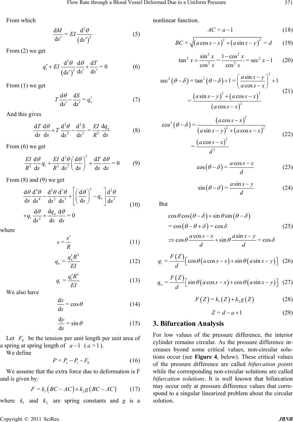 Flow Rate through a Blood Vessel Deformed Due to a Uniform Pressure371 From which 2 2 dd = dd MEI s s (5) From (2) we get 2 2 ddd =0 dd d tT qEI ss s (6) From (1) we get dd = dd n S T ss q (7) And this gives 22 222 d dddd = dd d dd n q TS TEI s ss ssR (8) From (6) we get 2 2 222 ddddd =0 ddd d t EI EIT q sss RRs ds (9) From (8) and (9) we get 3 423 2 423 2 ddd ddd dd ddd d d dd =0 dd d n n t q ss 2 s ss s q qss s (10) where = s sR (11) 3 =n n qR qEI (12) 3 =t t qR qEI (13) We also have d=cos d x s (14) d=sin d y s (15) Let 0 F be the tension per unit length per unit area of a spring at spring length of 1a (). >1a We define 0 =ei PPPF (16) We assume that the extra force due to deformation is F and is given by: 12 = F kBCAC kgBCAC (17) where and are spring constants and g is a nonlinear function. 1 k2 k =1 A Ca (18) 2 =cossin =BCas xas yd 2 (19) 22 22 22 sin1 cos tan== sec1 cos cos xx x x xx (20) 2 22 22 2 sin sec=tan1 =1 cos sin cos = cos asy asx asy asx asx (21) 2 2 22 2 2 cos cos = sin cos cos = asx asy asx asx d (22) cos cos= as d x (23) sin sin= asy d (24) But cos cossin sin =cos =cos cos sin cossin= cos asx asy dd (25) =coscossinsin t FZ qasxa d sy (26) =sincoscossin n FZ qasxa d sy (27) 12 = F ZkZkgZ (28) =1 Z da (29) 3. Bifurcation Analysis For low values of the pressure difference, the interior cylinder remains circular. As the pressure difference in- creases byond some critical values, non-circular solu- tions occur (see Figure 4, below). These critical values of the pressure difference are called bifurcation points while the corresponding non-circular solutions are called bifurcation solutions. It is well known that bifurcation may occur only at pressure difference values that corre- spond to a singular linearized problem about the circular solution. Copyright © 2011 SciRes. JBNB  Flow Rate through a Blood Vessel Deformed Due to a Uniform Pressure 372 Figure 4. Bifurcation points with solutions for N = 2, 3, and 4. In this section, we present the calculations to find the bifurcation points: the critical values of the pressure difference at which the vessel deforms into non-circular shapes. First, we set 1 ys (local angle) 2Momentys 3Shearys 4Tensionys 5 y sx 6 y sy where 2π 0,sN is the arclength. We define the state vector: 123456 =,,,,,Ysysysysysysys (30) Then the equations of equilibrium can be written as: 2 3 42 32 1 1 =,= = cos sin n t y y yy qP Ys FYPyy q y y 0 (31) with boundary conditions: 1 π 0= 2 y 36 0= 0=0yy 1 2ππ2π =2 yNN 3 2π=0yN 22 22 56 56 2π2π 00=yyyy NN ,n Pq =P, and defined by: t Pressure difference, q 151 =sincos cossin n FZ qyasyyas d 6 y , 151 =coscos sinsin t FZ qyasyyas d 6 y , where n and t are the normal and tangential com- ponents of stress per unit length, q q F Z is the force due to the springs, which is given by: 12 = F ZkZkgZ (32) where =1 Z da (33) And 22 56 =cos sindasy asy . (34) In the circular case, the Basic Solution is given by: 1 2 3 0 4 5 6 π 2 1 0 == cos sin ys s ys ys Ys ys P ys s ys s (35) where =1da , , , and =0Z=0 t q =0 n qg. Assuming that 0g0 , we have 00 =,YPYs F , P , and furthermore 0 Ys satisfies the boundary conditions for formula (31). The Fréchet derivative of , F YP at the basic solution is given by: 42 15 0 32 15 1 1 010000 001000 0 = 0 sin00000 cos00 000 nn Ytt qq yy yy FY qq yy yy y y 6 6 n t q y q y (36) where: =000 0 1156 ==== YY nttt YYY qqqq yyyy 0 (37) 01 5 =cos nY qks y (38) C opyright © 2011 SciRes. JBNB 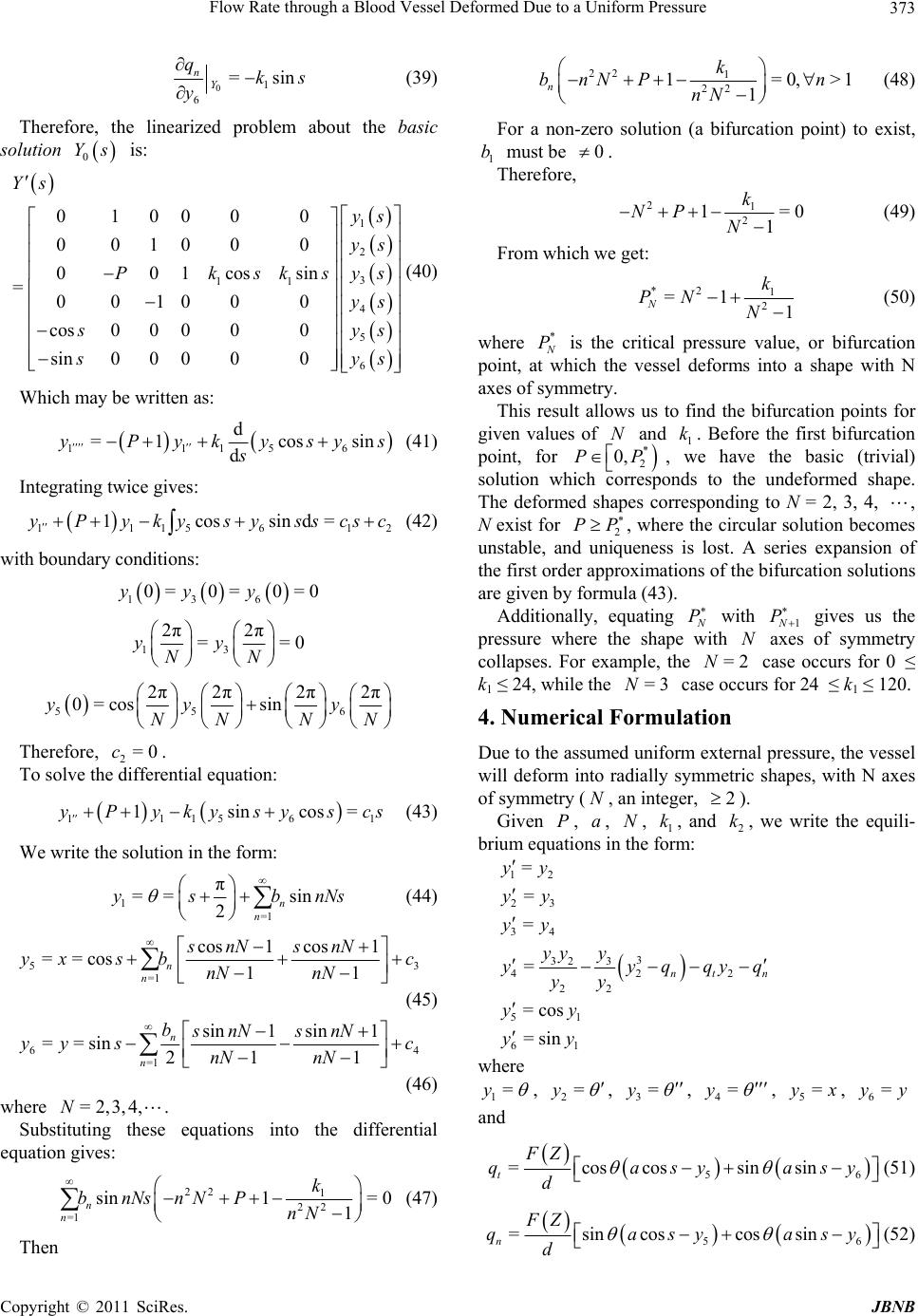 Flow Rate through a Blood Vessel Deformed Due to a Uniform Pressure373 01 6 =sin nY qks (39) y Therefore, the linearized problem about the solution is: (40) Which may be written as: basic 0 Ys 0 0 s 1 2 3 11 4 5 6 100 0 00100 0 001cossin =00100 0 cos00000 sin00 000 Y ys ys ys Pksks ys ys s ys s 56 d =1 cossinyPykysys s (41) Integrating twice gives: 2 w 111 d 111561 1cossind=yPyky sysscsc (42) ith boundary conditions: 136 0= 0= 0=0yyy 13 2π 2π ==0yy NN 55 2π2π2π2π 0=cos sinyy y NN NN 6 Therefore, To solve the fferential equation: 1 = 2=0c. di 11 156 1sincos y Py kysysc s (43) We write the solution in the form: 1 =1 2n n π == sin y sbnNs (44) 5 3 1 =1 cos1 cos ==cos 11 n n snN snN y xsb nN nN (45) c 6 4 =1 sin1sin1 ==sin21 1 n n bsnN snN yy sc nN nN (46) where Substituting these equations into the differential equation gives: =2,3,4,N. 22 1 22 =1 sin1= 0 n n k bnNsnNP (47) 22 1 22 1=0, 1 nk bnNP n nN >1 n-zero solution (a bifurcation point) to exist, must be (48) For a no 1 b 0 . ore, Theref 21 2 1=0 1 NP N (49) From whice get: k h w *2 1 2 =1 1 Nk PN N (50) here * N P is the critica nt, at which the vessel d wl pressure value, or bifurcation poi eforms into a shape with N axes of symmetry. This result allows us to find the bifurcation points for alugiven ves of N and 1 k. Before the first bifurcation point, for * 2 0, P P , we have the basic (trivial) solution which corr 2 esponds to the undeformed shape. The deformed shapes corresponding to N = 2, 3, 4, , N exist for PP , wherehe circular solution becomes unstable, ands is lost. A series expansion of the first order approximations of the bifurcation solutions are given by formula (43). Additionally, equating t nesunique N P with 1N P gives us the pressure where the shape with N axes of symmetry collapses. For example, the =2N case occurs for 0 ≤ k1 ≤ 24, while the =3N case occurs for 24 ≤ k1 ≤ 120. 4. Numerical Formulati extern ). , we write the equili- on Due to the assumed uniform al pressure, the vessel will deform into radially symmetric shapes, with N axes of symmetry ( N, an integer, 2 Given P, a, N, 1 k, and 2 k brium equations in the form: 12 =yy 23 =yy 34 =yy 3 32 3 422 2 =ntn yy qqyq yy 1nN Then 2 yy y 51 =cosyy 61 =sinyy where 1=y , 2=y , 3=y , 4=y , 5=yx, 6=yy and 56 coscos sinsin Za syasy = t F q (51) d 56 =sincos cossin n FZ qasya d sy (52) Copyright © 2011 SciRes. JBNB 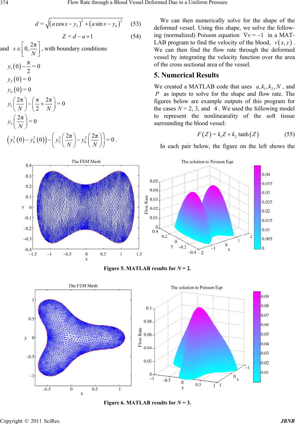 Flow Rate through a Blood Vessel Deformed Due to a Uniform Pressure Copyright © 2011 SciRes. JBNB 374 22 56 =cos sindasy asy (53) =1 Z da (54) and 2π 0,sN , with boundary conditions 1 π 0= 2 y 0 30=0y 60=0 y 1 2ππ2π=0 2 yNN 3 2π=0yN 22 22 56 56 2π2π 00 =yy yy0 N . We can then numerically solve for the shape of the deformed vessel. Using this shape, we solve the follow- g (normalized) Poisson equation in a MAT- A in L =1v B program to find the velocity of the blood, ,vxy. We can then find the flow rate through the deformed vessel by integrating the velocity function over the area of the cross sectional area of the vessel. 5. Numerical Results We created a MATLAB code that uses ,, ,ak kN, and P as inputs to solve for the shape and fl 12 ow rate. The this program ollowing m outputs of for figures below are example the cases N = 2, 3, and 4. We used the fodel to represent the nonlinearality of the soft tissue surrounding the blood vessel: 12 tanh= F ZkZk Z (55) In each pair below, the figure on the left shows the N Figure 5. MATLAB results for N = 2. Figure 6. MATLAB results for N = 3. 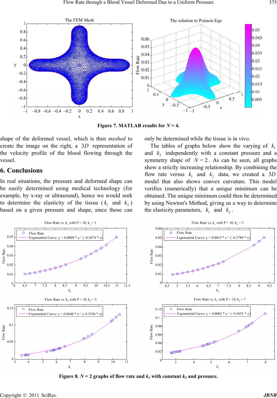 Flow Rate through a Blood Vessel Deformed Due to a Uniform Pressure375 Figure 7. MATLAB results for N = 4. shape of the deformed vessel, which is then meshed to create the image on the right, a representation of the velocity profile of the blood flowing through the vessel. 6. Conclusions In real situations, the pressure and deformed shape can be easily determined using medical technology (for example, by x-ray or ultrasound), hence we would seek to determine the elasticity of the tissue and) based on a given pressure and shape, sin only be determined while the tissue is in vivo. The tables of graphs below show the varying of and independently with a constant pressure an sym ry shape of . As can be seen, all gra show a strictly increalationship. By combining the flowversus data, we created a modat alsoex curvature. This m verifiesnumericallynique minimum obtaine The uni could then be determ by Newton'ving us a way to determ the elasticity param. 3D (1 k ce th 2 k ose can 1 k d a phs 3D odel ined ine 2 k met rate el th ( d. using =2N sing re 1 and ows conv ) that a minim Method, g ters, 1 k k sh que s e 2 k u um i and can be 2 k Figure 8. N = 2 graphs of flow rate and k1 with constant k2 and pressure. Copyright © 2011 SciRes. JBNB  Flow Rate through a Blood Vessel Deformed Due to a Uniform Pressure 376 Figure 9. N = 2 graphs of flow rate and k2 with constant k1 and pressure. Figure 10. 3D graph of flow ra te, k1, and k2 with constant pressure. 7. Acknowledgemen nce Foundation grant number 0552350 and UW-Eau Claire Reasearch Office for their support of the SUREPAM program. REFERENCES [1] C. Y. Wang, L. T. Watson and M. P. Kamat, “Buckling, ough a Tethered Elastic Cylinder Under External Pressure,” Journal of Applied Mechanics, Vol. 50, No. 1, pp. 13-18, 1983. doi:10.1115/1.3166981 ts Postbuckling, and Flow Rate Thr National Scie [2] D. H. Bergel, “The Properties of Blood Vessels,” In: Bio- mechanics, Its Foundations and Objectives, Eds., Pren- tice-Hall, Englewood, 1972. [3] Y. C. Fung, “Biomechanics, Mechanical Properties of C opyright © 2011 SciRes. JBNB  Flow Rate through a Blood Vessel Deformed Due to a Uniform Pressure377 Living Tissues,” Springer-Verlag, New York, 1990. [4] A. C. Guyton and J. E. Hall, “Textbook of Medical Phy- siology,” Saunders Company, 1996. [5] A. H. Moreno, A. I. Katz, L. D. Gold and R. V. Reddy, “Mechanics of Distension of Dog Veins and Other Very Thin-Walled Tubular Sturctures,” Circulation Research, Vol. 27, No. 6, 1970, pp. 1069-1080. [6] K. Osterloch, P. Gaehtgens, and A. Pries, “Determination of Microvascular Flow Pattern Formation in Vivo,” Ame- rican Journal of Botany, Vol. 278, No. 4, 2000, pp. H1142-H1152. [7] J. Stoer and R. Bulirsch, “Introduction to Numerical Analysis,” Springer-Verlag, New York, 1980. [8] M. B. M. Elgindi, D. H. Y. Yen and C. Y. Wang, “De- formation of a Thin-Walled Cylindrical Tube Submerged in a Liquid,” Journal of Fluids and Structure, Vol. 6, No. 3, 1992, pp. 353-370. doi:10.1016/0889-9746(92)90014-T Copyright © 2011 SciRes. JBNB |