International Journal of Communications, Network and System Sciences
Vol.10 No.08(2017), Article ID:78387,10 pages
10.4236/ijcns.2017.108B012
Radar-Communication Integration Based on MSK-LFM Spread Spectrum Signal
Zheng Dou, Xiaokang Zhong, Wenxu Zhang
College of Information and Communication Engineering, Harbin Engineering University, Harbin, China


Received: May 17, 2017; Accepted: August 11, 2017; Published: August 14, 2017
ABSTRACT
At present, with the progress and innovation of technology, the radar communication dual function wave has become a hot research at home and abroad. Excellent integrated waveform can make full use resources of combat platform, reduce the size of equipment, and realize the actual functionality of the reality of the battle-field without affecting the radar communication function. The MSK-LFM dual-function wave is a typical representative; it is based on LFM, through the MSK modulation to achieve the integration function. This paper proposes a scheme of combining the spread spectrum technology with the MSK-LFM waveform based on the previous literature. The simulation results show that the waveform envelope is more stable and the energy is more concentrated. With the introduction of spread-spectrum technology, the new waveform ambiguity function graph is much closer to the thumbtack than the traditional MSK-LFM waveform.
Keywords:
Radar-Communication Integration, Direct Sequence Spread Spectrum, Ambiguity Function, MSK-LFM

1. Introduction
With the development of science and technology and the complexity of the battlefield environment, the equipment systems of military field demand more and more. Combat platform had to be equipped more electronic equipment to meet the overall needs of the battlefield, such as: communications, radar, interference and so on. These devices integrated the combat platform, not only increases volume and energy consumption of the equipment system, but bring the interference between the various systems, it reduce the performance and efficiency of the entire platform, so the mobility was reduced, and the problem of concealment was ensued. Therefore, the integration of the combat system is imminent, It’s important to replacing simple linear superposition by combining different types of electronic devices with different functions. Integrated combat platform, can not only conducive to real-time coordination of the work of the system, but also contribute to the deployment of resources and the platform integration, improve reliability and portability of the equipment system.
In the literature [1], Chen Xingbo proposed a scheme that uses the LFM as the MSK carrier to form a new MSK-LFM signal. It both had radar detection function and communication function, then he analyzed it from the theory. The spread spectrum technology is applied to the radar signal, which can remarkably improve the performance of the signal ambiguity function. By comparing the LFM and the integrated waveform with the same conditions, we can see the performance of the wave-form after the spread spectrum is similar to the previous two, and it demonstrate the practicability of the new waveform.
2. Radar Communication Integrated Waveform Design Based on MSK-LFM Signal
2.1. MSK-LFM Integrated Communication Radar Waveform Signal Generated
Refer to the literature [2] [3], the kth symbol of the MSK signal can be expressed as:
 (1)
(1)
In this formula,  ,
,  is the initial phase determined by the kth symbol.
Reference to MSK modulation with a single carrier , the integrated waveform changes the carrier from  to
to , then the kth bit modulation symbol of the integrated waveform is:
 (2)
(2)
After the corresponding triangular transformation, Equation (2) can be expressed as an orthogonal form:
 (3)
(3)
It can be seen from the formula (1) (2) that the MSK-LFM signal and the MSK signal are different from the carrier, the baseband signal is the same, so we can conclude that and have the same properties of MSK. According to Equation (3) we can get the schematic diagram of the integrated waveform generation shown in Figure 1.
Refer to the he literature [4], if the phase of the signal is continuous, then the spectrum of the signal is narrow, the sidelobe descends faster, it also reduces the adjacent channel interference, and improves the bandwidth efficiency.
Through simulation can be drawn, the data and the time domain simulation

Figure 1. MSK-LFM flow diagram.
of the integrated waveform are shown below.
From Figure 2 and Figure 3, we can see, the waveform frequency slightly changed, the waveform become more and more dense, it meet the LFM waveform features. Because it uses MSK modulation, so the overall waveform phase is continuous.
2.2. Spectrum Analysis of MSK-LFM Radar Communication Integrated Waveform
When making integration waveform modulation, radar waveform is using LFM signal, communication waveform is MSK, the important reason is that MSK signal is advantage in bit error rate and power spectrum. At the same time, this waveform has less spectrum expansion and more concentrated spectrum. The signal spectrum is shown below.
According to Figures 4-6, the spectrum of the integrated waveform should be between 20 MHz and 25 MHz, and the energy outside should be close to zero, the result is same as the spectrum of the chirp signal what was given in the simulation results, therefore, there is a good radar detection performance.
3. Radar Communication Integrated Waveform Design Based on the Spread-Spectrum MSK-LFM Signal
3.1. Spread Spectrum Technology Application
Spread spectrum is spread original signal spectrum through some kind of modulation. The commonly used three types of spread-frequency technology are respectively: 1) Direct sequence spread spectrum, that is, represents a symbol with a pseudo code, and then the carrier is modulated. Because the chip rate is higher than the symbol rate, the spectrum of the modulated signal is extended; 2) Frequency hop-ping spread spectrum, that is, carrier frequency hopping in a symbol time, so achieve the purpose of spread spectrum; 3)

Figure 2. Raw data.

Figure 3. Integrated modulation waveform.

Figure 4. Spectrum after data modulation.

Figure 5. Spectrum after Full 1 data modulation.
Linear frequency modulation spread spectrum, that is, the carrier frequency varies linearly in one symbol, and it achieves the purpose of spread spectrum. Because

Figure 6. Standard LFM spectrogram.
using a shorter pulse width or more wide pulse bandwidth, the bandwidth of the signal after the spread spectrum becomes larger, and the narrowband interference bandwidth is relatively small, so the spread spectrum communication narrowband interference enhancement, while the spread spectrum communication also has Anti-eavesdropping, anti-multipath ability, can achieve the advantages of code division multiple access.
As it can be seen from the above analysis, if we use spread spectrum technology to achieve integrated waveform, it should have the same advantages and spread spectrum communication. And whether the pseudo-code sequence of direct sequence spread spectrum, or the chirp pulse of LFM spread, both has a certain distance measurement capability of speed. So, we can use spread spectrum technology to design integrated waveform.
In the literature [5], direct sequence spread spectrum (DSSS) is to use a set of spread spectrum codes to represent the information symbols, and then spread the spectrum to modulate the carrier wave. Theoretically, the ideal spreading code is a purely random sequence, but in the receiver, despreading requires a copy of the spread spectrum code that is the same as the spread spectrum code in transmitter. Some properties of PN sequence is similar to random noise, but unlike random noise sequences what cannot reproduce, the PN sequence is relatively easy to produce repeatedly and is easy to process, so it is beneficial to despreading and recovering symbol information.
In the literature [6], the communication data is spread by the spreading code to produce a digital baseband signal, then using the MSK-LFM way to digital modulation, the resulting signal have improved in the spectrum analysis and performance.
The pseudo-random sequence used as a spreading code can be expressed as:
 (4)
(4)
In the formula, L represents the sequence length of the PN code, represents the symbol period of the PN code; represents the i-th symbol of the PN code, the value is {1, −1}.
Since the direct sequence spread spectrum is represented by a set of spreading codes to represent a symbol information, the symbol period of the PN code is smaller than the symbol period of the information. Then, in the literature [7], the sequence after the direct sequence spread spectrum can be expressed as:
 (5)
(5)
The  is the ith symbol of the sequence after the direct spreading sequence, and the value is {−1, 1}.
Add the spread spectrum module on the original basis, the input data per unit time is increased, so the flow chart and the time domain sequence waveform are shown in Figure 7.
Compared with the pre-spread waveform in Figure 8 and Figure 9, we can see that the time-domain waveform is more closely.
3.2. Spectrum Analysis of the Integration of the Waveform after Spread Spectrum
The frequency spectrum of the waveform after the spread spectrum can be ob-

Figure 7. The flow chart of the integrated waveform.

Figure 8. Information symbols and sequences after spreading.
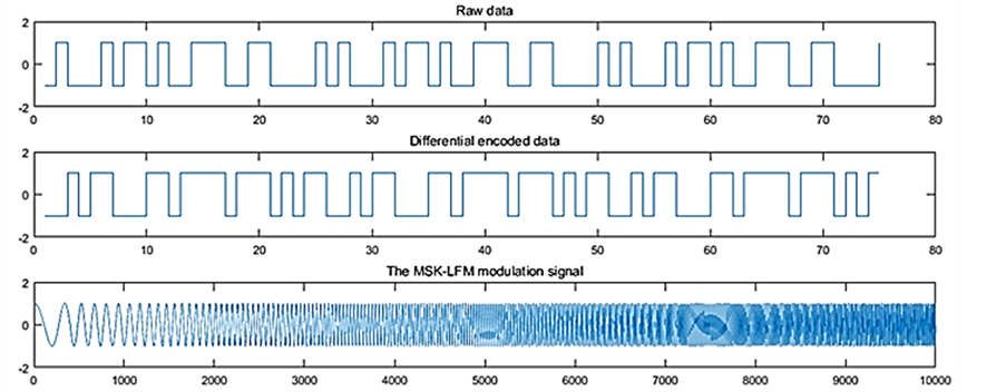
Figure 9. Integration of modulation waveform after the spread spectrum.

Figure 10. The spectrum after spreading.

Figure 11. The spectrum of all 1 data.

Figure 12. Standard LFM spectrogram.
tained as follows, in Figures 10-12, it can be found, the bandwidth has been expanded. We set the raw data to all 1 columns, the spectrum becomes approximately the same as the standard linear FM signal, and it ensures that the radar function can be achieved normally.
4. Performance Comparison of Ambiguity Function
Ambiguity function is one of the important indexes to measure radar waveform. It is usually used as a tool to study the performance of different waveforms. The ambiguity function of radar is defined as the model of two-dimensional cross correlation function of radar signal, which represents the result of matched filter output. The exact expression is:
 (6)
(6)
The ambiguity function of MSK-LFM is given in document [8] [9], as shown below:

 (7)
(7)

 (8)
(8)
In the formula,
 (9)
(9)
The literature [10] [11] give a ambiguity function three-dimensional diagram of the integrated waveform. As we can see from the diagram, the ambiguity function graph before the spread spectrum takes the shape of a pin shape, which is different from the “edge type” of the standard LFM ambiguity function diagram, this is the result of data modulation, and if the data becomes fully 1 or 0, the MSK-LFM degenerates into a normal LFM signal.
The essence of spread spectrum, in fact, is to replace the original data with the spread spectrum sequence in unit time, more data is modulated in per unit time, the resulting ambiguity function 3D graph is sharper. By comparing the zero delay slice and the zero Doppler slice before and after spread spectrum, it is found that there is almost no change in velocity resolution; In the zero delay slice, the width of the main lobe is narrowed, sidelobe is suppressed, and the range resolution is better.
5. Conclusions
MSK-LFM is a new type of radar communication dual function waveform. When the communication data is spread out and modulated again, the bandwidth of the signal can be extended and the sidelobe can be suppressed without affecting the function of the radar. The simulation results show that the performance of the new waveform is improved by the direct spread spectrum technology. And comparing the LFM signals in the same conditions, we can see that, although the integrated wave-form has a slight loss in the anti Doppler frequency shift, the performance of range detection and velocity detection is more obvious.
By analyzing the ambiguity function, we can see that the ambiguity function of the modulated waveform is significantly different from the LFM waveform. However, in the case of specific modulation data, it degenerates into a standard LFM ambiguity function graph. After spreading the spectrum, the ambiguity of the integrated waveform is sharper. Although the Doppler section remains the same, the main lobe of the delay section is narrower, so the range resolution is stronger.
Acknowledgements
This work is supported partly by National Natural Science Foundation of China under Grant No. 61301205 and No. 61571146, National Defense Based Science Research Program under Grant No. JCKY2013604B001. This paper is also funded by the International Exchange Program of Harbin Engineering University for Innovation-oriented Talents Cultivation. Meantime, all the authors declare that there is no conflict of interests regarding the publication of this article.
Cite this paper
Dou, Z., Zhong, X.K. and Zhang, W.X. (2017) Radar-Com- munication Integration Based on MSK-LFM Spread Spectrum Signal. Int. J. Communications, Network and System Sciences, 10, 108-117. https://doi.org/10.4236/ijcns.2017.108B012
References
- 1. Chen, X., Wang, X., Xu, S., et al. (2011) A Novel Radar Waveform Compatible with Communication. IEEE International Con-ference on Computational Problem-Solv- ing, Chengdu, 21-23 October 2011, 177-181. https://doi.org/10.1109/ICCPS.2011.6092272
- 2. Jamil, M., Zepernick, H.J. and Pettersson, M.I. (2008) On Integrated Radar and Communication Systems Using Oppermann Sequences. 2008 IEEE Military Communications Conference, San Diego, 16-19 November 2008, 1-6. https://doi.org/10.1109/MILCOM.2008.4753277
- 3. Xu, S., Chen, B. and Zhang, P. (2006) Radar-Communication Integration Based on DSSS Techniques. IEEE International Conference on Signal Processing, 2006.
- 4. Chunjie, Z. and Na, L. (2013) Modulation Parameter Estimation and Recognition of PSK Signals. Applied Science and Technology, 5, 40-43.
- 5. Garmatyuk, D. and Schuerger, J. (2008) Conceptual Design of a Dual-Use Radar/ Communication System Based on OFDM. 2008 IEEE Military Communications Conference, San Diego, 16-19 November 2008, 1-7. https://doi.org/10.1109/MILCOM.2008.4753063
- 6. Li, X.B. (2013) Integrated Radar and Communication Based on Multicarrier Frequency Modulation Chirp Signal. Dianzi Yu Xinxi Xuebao/Journal of Electronics & Information Technology, 35, 406-412. https://doi.org/10.3724/SP.J.1146.2012.00567
- 7. Surender, S.C., Narayanan, R.M. and Das, C.R. (2010) Performance Analysis of Communications & Radar Coexistence in a Covert UWB OSA System. In: Korbicz, J., Ed., Fault Diag-nosis: Models, Artificial Intelligence, Applications, 2010 Global Communications Conference GLOBECOM 2010, Miami, Flori-da, 6-10 December 2010, Springer Science & Business Media, 1-5. https://doi.org/10.1109/GLOCOM.2010.5683837
- 8. Roberton, M. and Brown, E.R. (2003) Integrated Radar and Communications Based on Chirped Spread-Spectrum Techniques. 2003 IEEE MTT-S International Microwave Symposium Digest, Philadelphia, 8-13 June 2003, Vol. 1, 611-614. https://doi.org/10.1109/MWSYM.2003.1211013
- 9. Zhang, W. and Liu, Z. (2014) Design and Implementation of Mod-ulator of a Novel Rader Waveform Compatible with Communication. IEEE International Workshop on Microwave and Milli-meter Wave Circuits and System Technology, 2014, 357- 360.
- 10. Shahriar, C., Abdelhadi, A. and Clancy, T.C. (2015) Overlapped-MIMO Radar Waveform Design for Coexistence with Communication Systems. 2015 IEEE Wireless Communica-tions and Networking Conference, 17, 223-228. https://doi.org/10.1109/WCNC.2015.7127473
- 11. Mahafza, B.R. (2008) Radar Signal Analysis and Processing Using Matlab.