Paper Menu >>
Journal Menu >>
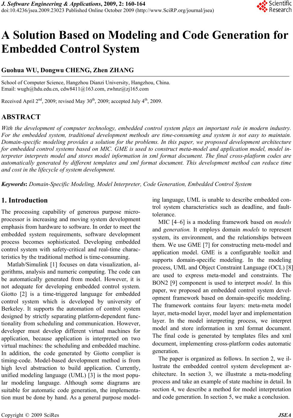 J. Software Engineering & Applications, 2009, 2: 160-164 doi:10.4236/jsea.2009.23023 Published Online October 2009 (http://www.SciRP.org/journal/jsea) Copyright © 2009 SciRes JSEA A Solution Based on Modeling and Code Generation for Embedded Control System Guohua WU, Dongwu CHENG, Zhen ZHANG School of Computer Science, Hangzhou Dianzi University, Hangzhou, China. Email: wugh@hdu.edu.cn, cdw8411@163.com, zw h n z @ zj 1 6 5.com Received April 2nd, 2009; revised May 30th, 2009; accepted July 4th, 2009. ABSTRACT With the development of computer technology, embedded control system plays an important role in modern industry. For the embedded system, traditional development methods are time-consuming and system is not easy to maintain. Domain-specific modeling provides a solution for the problems. In this paper, we proposed development architecture for embedded control systems based on MIC. GME is used to construct meta-model and application model, model in- terpreter interprets model and stores model information in xml format document. The final cross-platform codes are automatically generated by different templates and xml format document. This development method can reduce time and cost in the lifecycle of system development. Keywords: Domain-Specific Modeling, Mod e l Interpreter, Code Generation, Embedded Contro l System 1. Introduction The processing capability of generous purpose micro- processor is increasing and moving system development emphasis from hardware to software. In order to meet the embedded system requirements, software development process becomes sophisticated. Developing embedded control system with safety-critical and real-time charac- teristics by the traditional method is time-consuming. Matlab/Simulink [1] focuses on data visualization, al- gorithms, analysis and numeric computing. The code can be automatically generated from model. However, it is not adequate for developing embedded control system. Giotto [2] is a time-triggered language for embedded control system which is developed by university of Berkeley. It supports the automation of control system designed by strictly separating platform-dependent func- tionality from scheduling and communication. However, developer must develop different virtual machines for application, because application is interpreted on two virtual machines: the scheduling and embedded machine. In addition, the code generated by Giotto complier is timing-code. Model-based development method is from high level abstraction to build application. Currently, unified modeling language (UML) [3] is the most popu- lar modeling language. Although some diagrams are suitable for automatic code generation, the implementa- tion must be done by hand. As a general purpose model- ing language, UML is unable to describe embedded con- trol system characteristics such as deadline, and fault- tolerance. MIC [4–6] is a modeling framework based on models and generation. It employs domain models to represent system, its environment, and the relationships between them. We use GME [7] for constructing meta-model and application model. GME is a configurable toolkit and supports domain-specific modeling. In the modeling process, UML and Object Constraint Language (OCL) [8] are used to express meta-model and constraints. The BON2 [9] component is used to interpret model. In this paper, we proposed an embedded control system devel- opment framework based on domain-specific modeling. The framework contains four layers: meta-meta model layer, meta-model layer, model layer and implementation layer. In the model interpreting process, we interpret model and store information in xml format document. The final code is generated by templates files and xml document, implementing cross-platform codes automatic generation. The paper is organized as follows. In section 2, we il- lustrate the embedded control system development ar- chitecture. In section 3, we illustrate a meta-modeling process and take an example of state machine in detail. In section 4, we describe a method for model interpretation and code generation. In section 5, we make a conclusion. 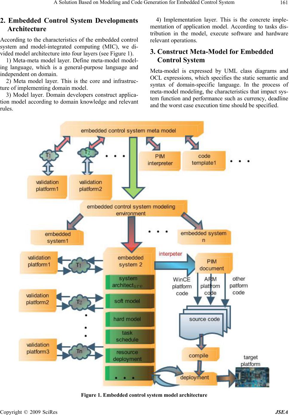 A Solution Based on Modeling and Code Generation for Embedded Control System161 2. Embedded Control System Developments Architecture According to the characteristics of the embedded control system and model-integrated computing (MIC), we di- vided model architecture into four layers (see Figure 1). 1) Meta-meta model layer. Define meta-model model- ing language, which is a general-purpose language and independe nt on domain. 2) Meta model layer. This is the core and infrastruc- ture of implementing domain model. 3) Model layer. Domain developers construct applica- tion model according to domain knowledge and relevant rules. 4) Implementation layer. This is the concrete imple- mentation of application model. According to tasks dis- tribution in the model, execute software and hardware relevant operations. 3. Construct Meta-Model for Embedded Control System Meta-model is expressed by UML class diagrams and OCL expressions, which specifies the static semantic and syntax of domain-specific language. In the process of meta-model modeling, the characteristics that impact sys- tem function and performance such as currency, deadline and the worst case execut i on t ime should be specified. Figure 1. Embedded control system model architecture Copyright © 2009 SciRes JSEA 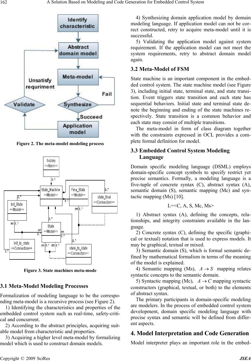 A Solution Based on Modeling and Code Generation for Embedded Control System 162 Figure 2. The meta-model modeling process Figure 3. State machines meta-mode 3.1 Meta-Model Modeling Processes Formalization of modeling language to be the correspo- nding meta-model is a recursive process (see Figure 2). 1) Identifying the characteristics and properties of the embedded control system such as real-time, safety-criti- cal and concurrent. 2) According to the abstract principles, acquiring suit- able model from characteristic and properties. 3) Acquiring a higher level meta-model by formalizing model which is used to construct domain models. 4) Synthesizing domain application model by domain modeling language. If application model can not be cor- rect constructed, retry to acquire meta-model until it is successful. 5) Validating the application model against system requirement. If the application model can not meet the system requirements, retry to abstract domain model again. 3.2 Meta-Model of FSM State machine is an important component in the embed- ded control system. The state machine model (see Figure 3), including initial state, terminal state, and state transi- tion. Event triggers state transition and each state has sequential behaviors. Initial state and terminal state de- note the beginning and ending of the state machines re- spectively. State transition is a common behavior and each state may consist of multiple transitions. The meta-model in form of class diagram together with the constraints expressed in OCL provides a com- plete formal definition for model. 3.3 Embedded Control System Modeling Language Domain specific modeling language (DSML) employs domain-specific concept symbols to specify restrict yet precise semantics. Formally, a modeling language is a five-tuple of concrete syntax (C), abstract syntax (A), semantic domain (S), semantic mapping (Mc) and syn- tactic mapping (Ms) [10]. L=<C, A, S, Mc, Ms> 1) Abstract syntax (A), defining the concepts, rela- tionships, and integrity constraints available in the lan- guage. 2) Concrete syntax (C), defining the specific (graphi- cal or textual) notation that is used to express models. It may be graphical, textual or mixed. 3) Semantic domain (S), which is formal semantic de- fined by mathematical formalism in terms of the meaning of the model is explained. 4) Semantic mapping (Ms), A S mapping relates syntactic concepts to the semantic domain. 5) Syntactic mapping (Mc), A Cmapping syntactic constructors (graphical, textual, or both) to the elements of abstract syntax. The primary participants in domain-specific modeling are modelers. In the process of embedded control system development, domain specific modeling language with precise syntax and semantic will be defined from differ- ent aspects. 4. Model Interpretation and Code Generation Model interpreter plays an important role in the embed- Copyright © 2009 SciRes JSEA  A Solution Based on Modeling and Code Generation for Embedded Control System163 ded control system development. We can develop dif- ferent interpreters for meeting requirements. The inter- preter is similar to a complier of advanced programming language. We take BON2 component to interpret model which is provided by GME. BON2 consists of class and interface, traversing objects in the model. The final cross-platform codes are automatic generated by differ- ent templates. 4.1 Model Interpretation Model interpreter is a component of GME, which is used to acquire objects’ information in application model. Developers can build various interpreters according re- quirements. The interpreters interpret model and store model information in PIM document (see Figure 4), fa- cilitating data transition and access. Figure 4. Model Interpretation PIM document Figure 5. Code generation architecture Figure 6. Process of code generation 4.2 Based on Template Code Generation In the process of code generation, we use different tem- plates to meet the needs of different platforms, which is similar to macros [11]. If there is no available template for specific application, the application developer can develop new templates according to the requirements. In this way, we can guarantee that the code supports differ- ent platforms (Figure 5). The workflow of code generation engine consists of two steps (see Figure 6). Firstly, invoking xml DOM parser to parse PIM and building DOM tree. Secondly, parsing template contents and replacing template con- tents with DOM tree. 5. Conclusions In this paper, we present a solution for developing the embedded control system. Relevant meta-model and model are expressed by class diagrams and a set of OCL constraints. A model interpreter is developed and the model information is interpreted, which is stored in PIM document. According to the system requirements, if we need new functions and want to support cross-platform, we have to construct new templates. This solution speeds up the application development and reduces the cost. What’s more, the application is easy to maintain by the modified meta-model. REFERENCES [1] P. Barnard, “Software development principles applied to graphical model development,” In AIAA Modeling and simulation Technologies conference an Exhibit, San Francisco, August 2005. [2] T. A. Henzinger and C. M. Kirsch, “The embedded ma- chine: Predictable, portable real-time code,” Proceedings of the International conference on Programming Lan- Copyright © 2009 SciRes JSEA  A Solution Based on Modeling and Code Generation for Embedded Control System Copyright © 2009 SciRes JSEA 164 guage Design and Implementation (PLDI), ACM press, pp. 315–326, 2002. [3] Object Management Group, “OMG unified modeling language specification,” http://www.uml.org/, 2007. [4] J. Sztipanovits and G. Karsai, “Model-integrated com- puting,” IEEE computer, pp. 110–112, April, 1997. [5] G. Karsai, A. Agrawal and A. Ledeczi, “A meta–model -driven MDA process and its tool,” Workshop in software Model Engineering, 2003. [6] G. Karsai, J. Sztipaovits, A. Ledeczi and T. Bapty. “Model-integrated development of embedded software,” In processing of the IEEE, pp.145–164, 2003. [7] A. Ledeczi, M. Maroti, G. Karsai, J. Garrett, J. Sprinkle, et al., “The generic modeling environment,” Workshop on Intelligent Signal Processing Budapest, Hungary, May 17, 2001. [8] Object Management Group, “Object constraint language,” http://www.omg.org/docs/ptc/03-10-14.pdf, 2003. [9] General Modeling Environment, http://www.isis.vander- bilt.edu/sites/default/files/GMEUMan.pdf, 2005. [10] T. Clark, A. Evans, S. Kent and P. Sammut, “The MMF approach to engineering object-oriented design lan- guage,” Workshop on Language Description, Tools and Applications, April 2001. [11] C. Buckl, A. Knoll, and G. Schrott. “Model-based devel- opment of fault-tolerant embedded software,” in second International symposium on Leveraging Applications of Formal Method, Verification and Validation, pp. 113–120, 2006. |