Optics and Photonics Journal, 2011, 1, 137-141
doi:10.4236/opj.2011.13023 Published Online September 2011 (http://www.SciRP.org/journal/opj)
Copyright © 2011 SciRes. OPJ
50 GHz Spaced 4 × 40 Gbit/s WDM Transmission over
700 km Using 6 ps Bandlimited RZ Signals
Mousaab M. Nahas
Electrical Engineering, Faculty of Engineering at Rabigh, King Abdulaziz University, Jeddah, KSA
E-mail: mousaab.n@gmail.com
Received July 16, 2011; revised August 15, 2011; accepted August 25, 2011
Abstract
In this paper, we present 50 GHz spaced 4 40 Gbit/s WDM transmission over 700 km using SMF-based
Effective Area Enlarged Positive Dispersion Fiber in a recirculating loop. The paper uses bandlimited RZ
signals and shows that transmission distance of 700 km can be achieved with BER 109 using 6 ps
pulsewidth for each data signal. To attain this, optical filters with sharp transmission characteristics are used
in both transmitter and receiver. The results demonstrated in this paper are based on simulation, and the au-
thor believes the propagation distance reached in the paper is the longest distance achieved for such system.
Keywords: Telecommunications, Fiber Optics Communications, Wavelength Division Multiplexing (WDM),
Optical Time Division Multiplexing (OTDM), High Speed Optical Transmission
1. Introduction
There has been a big demand to increase the transmission
capacities of optical fiber communication systems since
these systems were first developed. In fact, increasing
the capacities is still under development as telecommu-
nications keep expanding in time. It is well known by
telecommunication people that increasing the capacity of
optical fiber systems can be either achieved through
wavelength division mutliplexing (WDM) or optical time
division multiplexing (OTDM) or by a combination of
both. OTDM has economic advantage for network op-
erators since the number of terminals is reduced and also
because it can accommodate the existing single-band and
narrow-band erbium-doped fiber amplifiers (EDFA’s),
thus no need to spend money on the replacement by
broadband amplifiers. Considering this, it would be more
practical in many cases to generate 40 Gbit/s signal
through OTDM rather than using 4 × 10 Gbit/s WDM
signal. Moreover, it is possible to multiply this band-
width by combining multiple 40 Gbit/s signals through
WDM so that the capacity increases significantly. This
approach is commonly used in high speed optical trans-
mission systems where a lot of work has already been
done like [1], in which nonzero dispersion shifted fiber is
used. However, since single mode fiber (SMF) is the
basis of most existing fiber optic networks, it has been
more realistic to develop and investigate systems using
similar fiber in their transmission links. The most world-
wide deployed SMF fibers are standard single mode fiber
(SSMF) and large effective area fiber (LEAF). Some
work has been done on multiple 40 Gbit/s signals using
SSMF like [2], which used NRZ modulation format and
reached 511 km propagation distance. Another work was
presented in [3] showing 4 40 Gbit/s WDM transmis-
sion over 300 km using RZ format over SSMF. By and
large, the LEAF has already shown better results in all
modulation formats due to reduced nonlinear effects in
the fiber during propagation [4]. Also, RZ signals are
more reliable than NRZ and most common in conven-
tional transmission systems using OTDM [5]. Based on
that, this paper shall concentrate on transmitting multiple
40 Gbit/s signals over LEAF using bandlimited RZ sig-
nals. Similar work was already presented in [6] showing
good transmission results over 480 km distance only.
Our paper demonstrates successful transmission of 4-
channels 40 Gbit/s WDM signals over 700 km using
SMF-based effective area enlarged fiber (or LEAF) with
positive dispersion. The four WDM signals are 50 GHz
spaced (i.e. 0.4 nm), thus the system is considered dense
wavelength division multiplexing (DWDM) system. We
believe that simulating four DWDM is somehow suffi-
cient to predict the behavior of systems carrying higher
number of channels while using less CPU time. In such
regime, the investigation would include finding the op-
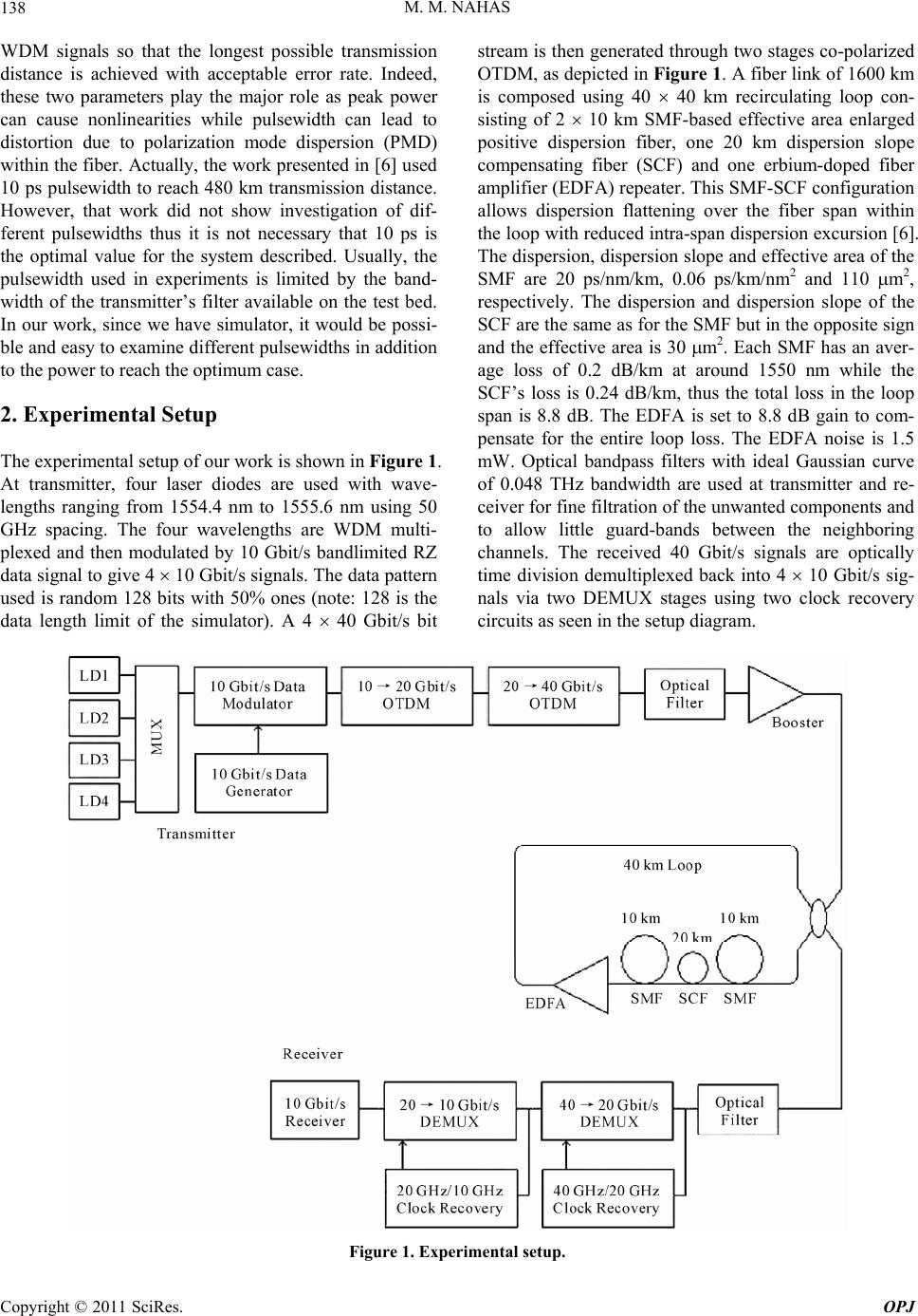
timum input power and pulsewidth of the transmitted 4
M. M. NAHAS
138
WDM signals so that the longest possible transmission
distance is achieved with acceptable error rate. Indeed,
these two parameters play the major role as peak power
can cause nonlinearities while pulsewidth can lead to
distortion due to polarization mode dispersion (PMD)
within the fiber. Actually, the work presented in [6] used
10 ps pulsewidth to reach 480 km transmission distance.
However, that work did not show investigation of dif-
ferent pulsewidths thus it is not necessary that 10 ps is
the optimal value for the system described. Usually, the
pulsewidth used in experiments is limited by the band-
width of the transmitter’s filter available on the test bed.
In our work, since we have simulator, it would be possi-
ble and easy to examine different pulsewidths in addition
to the power to reach the optimum case.
2. Experimental Setup
The experimental setup of our work is shown in Figure 1.
At transmitter, four laser diodes are used with wave-
lengths ranging from 1554.4 nm to 1555.6 nm using 50
GHz spacing. The four wavelengths are WDM multi-
plexed and then modulated by 10 Gbit/s bandlimited RZ
data signal to give 4 10 Gbit/s signals. The data pattern
used is random 128 bits with 50% ones (note: 128 is the
data length limit of the simulator). A 4 40 Gbit/s bit
stream is then generated through two stages co-polarized
OTDM, as depicted in Figure 1. A fiber link of 1600 km
is composed using 40 40 km recirculating loop con-
sisting of 2 10 km SMF-based effective area enlarged
positive dispersion fiber, one 20 km dispersion slope
compensating fiber (SCF) and one erbium-doped fiber
amplifier (EDFA) repeater. This SMF-SCF configuration
allows dispersion flattening over the fiber span within
the loop with reduced intra-span dispersion excursion [6].
The dispersion, dispersion slope and effective area of the
SMF are 20 ps/nm/km, 0.06 ps/km/nm2 and 110 m2,
respectively. The dispersion and dispersion slope of the
SCF are the same as for the SMF but in the opposite sign
and the effective area is 30 m2. Each SMF has an aver-
age loss of 0.2 dB/km at around 1550 nm while the
SCF’s loss is 0.24 dB/km, thus the total loss in the loop
span is 8.8 dB. The EDFA is set to 8.8 dB gain to com-
pensate for the entire loop loss. The EDFA noise is 1.5
mW. Optical bandpass filters with ideal Gaussian curve
of 0.048 THz bandwidth are used at transmitter and re-
ceiver for fine filtration of the unwanted components and
to allow little guard-bands between the neighboring
channels. The received 40 Gbit/s signals are optically
time division demultiplexed back into 4 10 Gbit/s sig-
nals via two DEMUX stages using two clock recovery
circuits as seen in the setup diagram.
Figure 1. Experimental setup.
Copyright © 2011 SciRes. OPJ
M. M. NAHAS
Copyright © 2011 SciRes. OPJ
139
For evaluation, the simulator is set such that it pro-
duces performance results every 1 km transmission.
3. Results and Analysis
To study the performance of the system described, dif-
ferent peak power and pulsewidth (through full wave
half maximum, FWHM) values of the propagating 4 40
Gbit/s signals were examined against transmission dis-
tance. Commonly, the performance is evaluated via Q-
value or BER where good transmission should exhibit Q
6 or BER 109. Therefore, the optimum distance is
effectively the maximum distance that satisfies the above
condition. The simulation used peak power values in the
range between 1 - 10 mW and FWHM between 5 - 8 ps,
where outside these intervals the performance degrades
dramatically. This is explained as if the peak power was
too small, the system would be impaired by noise where
optical signal to noise ratio (OSNR) decreases over short
distance. In contrast, if the peak power was too high, the
system would be impaired by nonlinearities thus the sig-
nal distorts shortly, resulting in high BER. On the other
hand, if the pulsewidth was too small, the data signal
would loose some of its information and thus errors will
be counted upon transmission. If the pulsewidth was too
broad, polarization mode dispersion (PMD) would result
in inter-symbol interference (ISI) between the neighbor-
ing bits thus data will face considerable distortion over
short propagation distance. This argument leads us to
explore the best values among those in the intervals
mentioned above, at which signals are allowed to reach
their maximum possible propagation distance. For accu-
racy, the simulation was run four times for each test and
the results were based on average values. This was done
as amplifier noise is random thus the results slightly de-
viate every time the same test is run. Figure 2 shows the
major results obtained from this experiment. It presents
the maximum transmission distance obtained with Q 6
versus peak power for each 40 Gbit/s signal using dif-
ferent FWHM values.
It is obvious from Figure 2 that the maximum propa-
gation distance differs from one channel to another, and
also differs for different parameters. Apparently, the side
signals (Ch. 1 and Ch. 4) often performs better than the
FWHM = 5 ps
0
100
200
300
400
500
600
700
800
900
1000
01234567891011
Peak Power (mW)
Transmission Distance (km
)
Ch. 1
Ch. 2
Ch. 3
Ch. 4
FWHM = 6 ps
0
100
200
300
400
500
600
700
800
900
1000
0123456789101
Peak Power (mW)
Transmission Distance (km
1
)
Ch. 1
Ch. 2
Ch. 3
Ch. 4
(a) (b)
FWHM = 7 ps
0
100
200
300
400
500
600
700
800
900
1000
01234567891011
P eak P ower (mW)
Transmi ss ion Di st ance (k m)
Ch. 1
Ch. 2
Ch. 3
Ch. 4
FWHM = 8 ps
0
100
200
300
400
500
600
700
800
900
1000
01234567891011
Peak Power (mW)
Transmi ss i on Di stanc e (k m )
Ch. 1
Ch. 2
Ch. 3
Ch. 4
(c) (d)
Figure 2. Transmission distance versus peak power for different values of FWHM: (a) 5 ps; (b) 6 ps; (c) 7 ps; and (d) 8 ps.
Channels’ definitions: Ch. 1 = 1554.4 nm; Ch. 2 = 1554.8 nm; Ch. 3 = 1555.2 nm; Ch. 4 = 1555.6 nm).
(
M. M. NAHAS
Copyright © 2011 SciRes. OPJ
140
mid channels due to one side interaction thus less in-
ter-channel crosstalk caused by cross phase modulation
(XPM) and four wave mixing (FWM). Furthermore, Ch.
4 is still better than Ch. 1 due to better noise characteris-
tics within its band at the transmitter. This can be noticed
in Figure 3 that shows the spectra of the four channels in
the transmitter’s filter (note that Ch. 4 is the first channel
on the right).
To decide on the optimum parameters, the perform-
ance of the four signals was compared for different
FWHM, and the optimal transmission distance was de-
termined based on a comparison between the worst sig-
nals’ behaviors. In details, for FWHM = 5 ps shown in
(a), good overall performance was achieved for peak
power around 4 mW where the maximum distance of the
worst signal was 540 km (Ch. 3) although Ch. 4 reached
820 km. Comparing this with other graphs, for FWHM =
6, 7 and 8 ps as in (b), (c) and (d), respectively, good
performance was achieved at around 3 mW peak power.
This difference in optimum peak power is understood as
for 5 ps the signal lost little part of its power thus it
needed more power to hit the nonlinear window. How-
ever, for 6, 7 and 8 ps pulsewidths, the worst case was:
700 km (Ch. 2), 623 km (Ch. 3) and 580 km (Ch. 2),
respectively. As a result of comparing the worst cases,
the maximum transmission distance with Q 6 achieved
for this system can be 700 km and the optimum peak
power and pulsewidth are 3 mW and 6 ps, respectively.
At these particular values, a good compromise between
noise and nonlinear impairments has been attained, and
the pulses are broad enough to contain full information
and power of the data bits while do not overlap due to
PMD effect. Since the transmission results shown in Fig-
ure 2 based on Q-value assessment, it would have been
necessary to shows Q-value versus transmission distance
for the given parameters. However, as we are most inter-
ested in the optimum parameters, Figure 4 shows Q-
value evolution with distance for all channels using 3
mW peak power and 6 ps pulsewidth.
4. Conclusions
In this paper, we demonstrated simulation results for 50
GHz spaced 4 40 Gbit/s WDM signals transmission
using bandlimited RZ modulation format over SMF-
Based Effective Area Enlarged Positive Dispersion Fiber.
Transmission performance with BER 109 was suc-
cessfully achieved over 700 km using 3 mW peak power
and 6 ps pulsewidth for each data signal. The experiment
used optical filters with sharp transmission characteris-
tics in both transmitter and receiver.
5. Acknowledgements
The author would like to thank Marc Eberhard, who is a
lecturer in Electrical Engineering at Aston University
Figure 3. Signals’ spectra using Gaussian filter with 48 GHz bandwidth.
M. M. NAHAS
Copyright © 2011 SciRes. OPJ
141
4
5
6
7
8
9
10
11
12
13
14
15
0100 200 300 400 500600 700 800 90010001100
Trans m i ssi on Distanc e (km )
Q-Val ue
Ch. 1
Ch. 2
Ch. 3
Ch. 4
Figure 4. Q-value versus propagation distance for all chan-
nels using peak power = 3 mW and FWHM = 6 ps. (Chan-
nels’ definitions: Ch. 1 = 1554.4 nm; Ch. 2 = 1554.8 nm; Ch.
3 = 1555.2 nm; Ch. 4 = 1555.6 nm).
(UK), for providing the author with his self-developed
XML-based simulation code.
6. References
[1] J.-X. Cai, C. R. Davidson, M. Nissov, H. F. Li, W. T.
Anderson, Y. Cai, L. Li, A. N. Pilipetskii, D. G. Foursa,
W. W. Patterson, P. C. Corbett, A. J. Lucero and N. S.
Bergano, “Transmission of 40-Gb/s WDM Signals over
Transoceanic Distance Using Conventional NZ-DSF with
Receiver Dispersion Slope Compensation,” Journal of
Lightwave Technology, Vol. 24, No. 1, 2006, pp. 191-
200. doi:10.1109/JLT.2005.861138
[2] S. S. Lee, H.-W. Cho, S.-K. Lim, K.-M. Yoon, Y.-G. Lee,
and J. Ko, “Field Trial of 1.6 Tb/s (40 channels × 40 Gb/s)
NRZ Signals over 511 km Standard Single Mode Fiber
Using Conventional Optical Amplifiers,” IEEE Interna-
tional Conference on Communications (IEEE ICC 2005),
Vol. 3, 2005, pp. 1598-1602.
[3] C. M. Weinert, R. Ludwig, W. Pieper, H. G. Weber, D.
Breuer, K. Petermann and F. Kuppers, “40 Gb/s and 4
40 Gb/s TDM/WDM Standard Fiber Transmission,”
Journal of Lightwave Technology, Vol. 17, No. 11, 1999,
p. 2276. doi:10.1109/50.803020
[4] A. Tan and E. Pincemin, “Performance Comparison of
Duobinary Formats for 40-Gb/s and Mixed 10/40-Gb/s
Long-Haul WDM Transmission on SSMF and LEAF Fi-
bers,” Journal of Lightwave Technology, Vol. 27, No. 4,
2009, pp. 396-408. doi:10.1109/JLT.2008.929117
[5] R. Ludwig, U. Fieste, E. Dietrich, H. G. Weber, D. Breuer,
M. Martin and F. Kuppers, “Experimental Comparison of
40Gbit/s RZ And NRZ Transmission over Standard
Singlemode Fiber,” Electronics Letters, Vol. 35, No. 25,
1999, pp. 2216-2218. doi:10.1049/el:19991504
[6] K. Tanaka, I. Morita and N. Edagawa, “50 GHz Spaced
40 Gbit/s 25WDM Transmission over 480 km Using
Bandlimited RZ Signals,” Electronics Letters, Vol. 37,
2001, pp. 775-776. doi:10.1049/el:20010540