 Journal of Software Engineering and Applications, 2011, 4, 534-545 doi:10.4236/jsea.2011.49062 Published Online September 2011 (http://www.SciRP.org/journal/jsea) Copyright © 2011 SciRes. JSEA Research and Application of Code Automatic Generation Algorithm Based on Structured Flowchart Xiang-Hu Wu, Ming-Cheng Qu, Zhi-Qiang Liu, Jian-Zhong Li School of Computer Science and Technology, Harbin Institute of Technology, Harbin, China. Email: Wuxianghu@hit.edu.cn Received June 17th, 2011; revised July 15th, 2011; accepted July 26th, 2011. ABSTRACT It is of great sign ificance to automatically generate code fro m structured flowchart. There are some deficiencies in ex- isting researches, and their key algorithms and technologies are not elaborated, also there are very few full-featured integrated development platforms that can generate code automatically based on structured flowchart. By analyzing the characteristics of structured flowchart, a structure identification algorithm for stru ctured flowcha rt is put forward. The correctness of algorithm is verified by enumeration iteration. Then taking the identified flowchart as input, an auto- matic code generation a lgorithm is proposed. Also the corr ectness is verified by enumeratio n iteration. Fina lly an inte- grated development platform is developed using those algorithms, including flowchart modeling, code automatic gen- eration, CDT\GCC\GDB etc. The correctness and effectiveness of algorithms proposed are verified through practical operations. Keywords: Automatic Generation of Codes, Structured Flowchart, Identification of Structure, Integrated Development Platform 1. Introduction Software development ideas based on MDA (Model Driven Architecture) have attracted much attention from the research community in recent years [1,2]. MDA is first proposed by OMG. It is a methodology and standard system by which software systems are built on the basis of a variety of models, through model transformation to drive system development [3]. The development of Model-driven software is a hot issue in the current field of software engineering, and it has become a new soft- ware development paradigm to improve the quality and efficiency of software development [4]. Here the code generation indicates that a generator reads the code or documents related to the graphic model and generates high-level language program, just like C, C + +, Java, Perl, Ruby, Python and HTML and so on.. There are many relevant researches about automatic code generation, such as: the solution , for automatic co de generation based on metadata-driven, by the framework of .Net, achieve the objective of automatic generation of storage procedure and trigger in database [3]; A tool based on design pattern can automatically generate a design pattern of abstract level [4]; A automatic code generation technology based on uml meta model can generate the architecture of system, and meanwhile the generated code can reflect the hierarchy of original model [5]; By analyzing the synergy effect of the syntax envi- ronment between WWW and WEB, a WEB code auto- matic generation prototype system is proposed based on XML [6]. A UML tool can convert UML graphics into specific language to predict the performance of system [7]. In the field of multi-media, a data flow code auto- matic generation technology based on template can re- duce the workload of direct memory access, meanwhile it can maintain the performance of multi-media computing [8]. A fast automatic code generator based on preferred pattern matching automata is proposed, it can be used to verify the correctness of UML state diagram and collabo- ration diagram, by insert primitives at fixed point of model, it can generate code automatically [9]. The tools, like I-Logix, Rhapsody, based on state machine, can gen- erate code which can run at their real-time frameworks.  Research and Application of Code Automatic Generation Algorithm Based on Structured Flowchart535 2. Related Research and Main Contribution 2.1. Related Research Flowchart plays an important role in system requirements analysis, preliminary design and detailed design aspects. It is particularly important when making communication and discussion, analysis and design of algorithms. But the traditional use of the flowchart are only limited to display, communication, description, and its role is only limited to graphical, intuitive, clear and easy communi- cation and documentation compilation. So, automatic generation of a specific language code from flowchart will be a very important practical significance, it allows the designer to design the system from high-level func- tions without concerning for complicated code, and is more in line with the objective of MDA [10]. Recently, there are some reports about the automatic generation of code from flowchart. However, these re- searches all have certain deficiencies, and the core algo- rithm and technologies are not public, so the accuracy and validity are hard to be convinced. More researches, such as “AthTek Code to FlowChart”, “Code to Chart”, “AutoFlowchart” etc, are just its reverse engineering, that is automatic generation of flowchart from code,. Hemlata Dakhore presented a strategy based on XML parser to generate code [11]. But the paper did not dis- cuss how to identify the semantic of a specific flowchart. That is, the identification method of selection and loop are not discussed. According to the method, it must first determine whether a judgment node is a loop or selection, this information must be specified in advance by the modeler. If so it will lose the flexibility and conven ience of a flowchart model, and also lack of automation and intelligence. And the paper only gives a sequence- selec- tion simple example, for the algorithms of converting flowchart to XML and automatically ge nerating code are not discussed. Martin C. Carlisle proposed a modeling and simulation system RAPTOR [12], which provides selection and loop primitives. This means that the mod- elers must know what kinds of structures they should draw in advance. While in standard flowchart there is only a judgment node, loop and selection nodes should be determined according to the semantic of a specific flowchart. So the RAPTOR is a specialized and non- standard graphical language. And this article only de- scribes the functions of a system. Tia Watts gave a flow- chart modeling tool SFC, which can be used to auto- matically generate code [13]. But its operation is me- chanical, can only inserted pre-standard graphical ele- ments from fixed points, the flexibility is very low, op- eration is not convenient, lack of scalability, do not sup- port the component model. Most importantly, it does not support nesting flowchart (processing nodes can be im- plemented as sub-flow chart). Kanis Charntaweekhun simply introduced the methods of how to use flow chart to program and its advantages, and said that the devel- oped system can transform flowchart into code. But, the conversion algorithm, key technologies and data struc- tures are not mentioned, and the examples given are very simple [14]. 2.2. Main Contributions Main contribution By analyzing the characteristics flow- chart, we put forward a structure identificatio n algorithm for structured flowchart, after then taking the flowchart identified in previous step as input, a algorithm which can generate code automatically is proposed. We verify the correctness and effectiveness of algorithms proposed using enumeration iteration strategy. At last we designed and implemented an integrated development platform based on Eclipse and algorithms presented above; the platform uses a structured flowchart to describe program logic and can convert flowchart model into standard ANSI-C code. At the same time code editor (CDT), compilation tools (GCC) and debug- ging tools (GDB) are all integrated into this platform. Build the system with flowchart: Tasks and interrupt service can be modeled, platform can generate an in- stance of the task or interrupt, and also support nest- ing flowchart model and code generation. Variables and head-file management: Management of global variables, local variables, macros, and various header files. 3. Structured Flowchart Any complex algorithms can be composed of three basic structures, sequence, selection and loop. These basic structures can be coordinates, they can include each other, but they can not cross and directly jump to another structure from the internal of a structure. As the whole algorithm is constructed by these three structures, just like composed by modules, therefore, it has the charac- teristics of clear structure, easily verifying accuracy and correcting errors [15,16]. Flowchart is independent of any programming lan- guage. Structured flowchart can be further divided into five kinds of structures: sequence, selection, more selec- tion, pre-check loop and post-check loop, as shown in Figure 1. Any complex flow chart can be built by the combination or the nest of the five basic control struc- tures. Now there are many tools support flowchart mod- eling, such as Visio, Word, Rose and so on. In order to make flowchart model more clear and in- tuitive and unambiguously, as shown in Figure 3, in ad- dition to the order stru cture, the remaining four structures all use a judge node, when the executions exit their Copyright © 2011 SciRes. JSEA 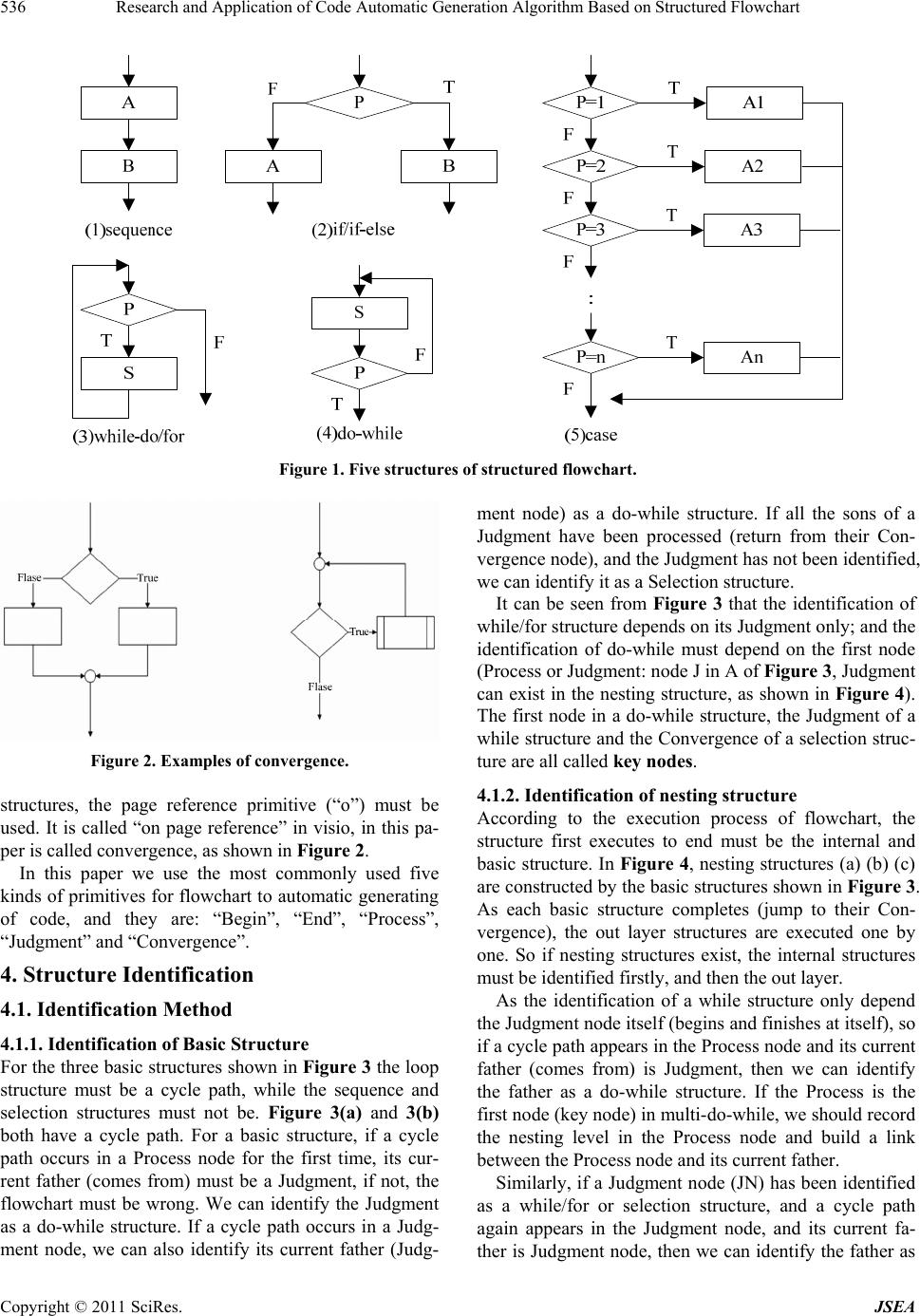 Research and Application of Code Automatic Generation Algorithm Based on Structured Flowchart Copyright © 2011 SciRes. JSEA 536 Figure 1. Five structures of structured flowchart. Figure 2. Examples of convergence. structures, the page reference primitive (“o”) must be used. It is called “on page reference” in visio, in this pa- per is called convergence, as shown in Figure 2. In this paper we use the most commonly used five kinds of primitives for flowchart to au tomatic generating of code, and they are: “Begin”, “End”, “Process”, “Judgment” and “Convergence”. 4. Structure Identification 4.1. Identification Method 4.1.1. Identification of Basic Structure For the three basic structures shown in Figure 3 the loop structure must be a cycle path, while the sequence and selection structures must not be. Figure 3(a) and 3(b) both have a cycle path. For a basic structure, if a cycle path occurs in a Process node for the first time, its cur- rent father (comes from) must be a Judgment, if not, the flowchart must be wrong. We can identify the Judgment as a do-while structure. If a cycle path occurs in a Judg- ment node, we can also identify its current father (Judg- ment node) as a do-while structure. If all the sons of a Judgment have been processed (return from their Con- vergence node), and the Judgment has not been identified, we can identify it as a Selection stru cture. It can be seen from Figure 3 that the identification of while/for structure depends on its Judgment only; and the identification of do-while must depend on the first node (Process or Judgment: node J in A of Figure 3, Judgment can exist in the nesting structure, as shown in Figure 4). The first node in a do-while structure, the Judgment of a while structure and the Convergence of a selection struc- ture are all called key nodes. 4.1.2. Identification of nesting structure According to the execution process of flowchart, the structure first executes to end must be the internal and basic structure. In Figure 4, nesting structures (a) (b) (c) are constructed by the basic structures shown in Figure 3. As each basic structure completes (jump to their Con- vergence), the out layer structures are executed one by one. So if nesting structures exist, the internal structures must be identified firstly, and then the out layer. As the identification of a while structure only depend the Judgment node itself (begins and finishes at itself), so if a cycle path appears in the Process node and its current father (comes from) is Judgment, then we can identify the father as a do-while structure. If the Process is the first node (key node) in multi-do-while, we sh ould record the nesting level in the Process node and build a link between the Process nod e and its current father. Similarly, if a Judgment node (JN) has been identified as a while/for or selection structure, and a cycle path again appears in the Judgment node, and its current fa- ther is Judgment node, then we can identify the father as 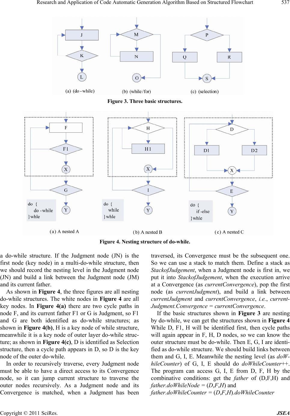 Research and Application of Code Automatic Generation Algorithm Based on Structured Flowchart537 Figure 3. Three basic structures. Figure 4. Nesting structure of do-while. a do-while structure. If the Judgment node (JN) is the first node (key node) in a multi-do-while structure, then we should record the nesting level in the Judgment node (JN) and build a link between the Judgment node (JM) and its current father. As shown in Figure 4, the three figures are all nesting do-while structures. The white nodes in Figure 4 are all key nodes. In Figure 4(a) there are two cycle paths in node F, and its current father F1 or G is Judgment, so F1 and G are both identified as do-while structures; as shown in Figure 4(b), H is a key node of while structure, meanwhile it is a key node of outer layer do-while stru c- ture; as shown in Figure 4(c), D is identified as Selection structure, then a cycle path appears in D, so D is the key node of the outer do-while. In order to recursively traverse, every Judgment node must be able to have a direct access to its Convergence node, so it can jump current structure to traverse the outer nodes recursively. As a Judgment node and its Convergence is matched, when a Judgment has been traversed, its Convergence must be the subsequent one. So we can use a stack to match them. Define a stack as StackofJudgement, when a Judgment node is first in, we put it into StackofJudgement, when the execution arrive at a Convergence (as currentConvergence), pop the first node (as currentJudgment), and build a link between currentJudgment and currentConvergence, i.e., current- Judgment.Convergence = currentConvergence. If the basic structures shown in Figure 3 are nesting by do-while, we can get the structures shown in Figure 4 While D, F1, H will be identified first, then cycle paths will again appear in F, H, D nodes, so we can know the outer structure must be do-while. Then E, G, I are identi- fied as do-while structure. We should build links between them and G, I, E. Meanwhile the nesting level (as doW- hileCounter) of G, I, E should do doWhileCoun ter++. The program can access G, I, E from D, F, H by the combinative conditions: get the father of (D,F,H) and father.doWhileNo de = (D,F,H) and father.doWhileCounter = (D,F,H).doWhileCounter Copyright © 2011 SciRes. JSEA 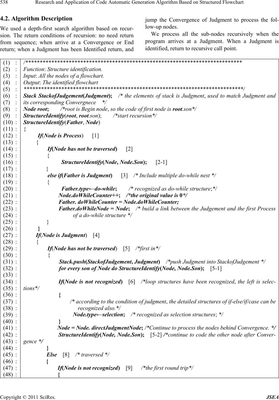 Research and Application of Code Automatic Generation Algorithm Based on Structured Flowchart 538 4.2. Algorithm Description We used a depth-first search algorithm based on recur- sion. The return conditions of recursion: no need return from sequence; when arrive at a Convergence or End return; when a Judgment has been Identified return, and jump the Convergence of Judgment to process the fol- low-up nodes. We process all the sub-nodes recursively when the program arrives at a Judgment. When a Judgment is identified, return to recursive call point. (1) : (2) : (3) : (4) : (5) : (6) : (7) : (8) : (9) : (10) : (11) : (12) : (13) : (14) : (15) : (16) : (17) : (18) : (19) : (20) : (21) : (22) : (23) : (24) : (25) : (26) : (27) : (28) : (29) : (30) : (31) : (32) : (33) : (34) : (35) : (36) : (37) : (38) : (39) : (40) : (41) : (42) : (43) : (44) : (45) : (46) : (47) : (48) : /*************************************************************************** Function: Structure identification. Input: All the nodes of a flowchart. Output: The identified flowchart ************* ********* ********* ****** ********* ********* ********* ********* ***/ Stack StackofJudgement(Judgment); /* the elements of stack is Judgment, used to match Judgment and its corresponding Convergnece */ Node root; /*root is Begin node, so the code of first node is root.son*/ StructureIdentify(root, root.son); /*start recursion*/ StructureIdentify(Father, Node) { If(Node is Process) [1] { If(Node has not be traversed) [2] { StructureIdentify(Node, Node.Son); [2-1] } else if(Father is Judgment) [3] /* Include multiple do-while nest */ { Father.type←do-while; /* recognized as do-while structure;*/ Node.doWhileCounter++; /*the original value is 0*/ Father. doWhileCounter = Node.doWhileCounter; Father.doWhileNode = Node; /* build a link between the Judgement and the first Process of a do-while structure */ } } If(Node is Judgment) [4] { If(Node has not be traversed) [5] /*first in*/ { Stack.push(StackofJudgement, Judgment) /*push Judgment into StackofJudgement */ for every son of Node do StructureIdentify(Node, Node.Son); [5-1] If(Node is not recognized) [6] /*loop structures have been recognized, the left is selec- tions*/ { /* according to the condition of judgment, the detailed structures of if-else/if/ca s e can be recognized al so.*/ Node.type←selection; /* recognized as selection structures; */ } Node = Node. directJudgmentNode; /*Continue to process the nodes behind Convergence. */ StructureIdentify(Node, Node.Son); [5-2] /*continue to code the other node after Conver- gence */ } Else [8] /* traversed */ { If(Node is not recognized) [9] /*the first round trip*/ { Copyright © 2011 SciRes. JSEA 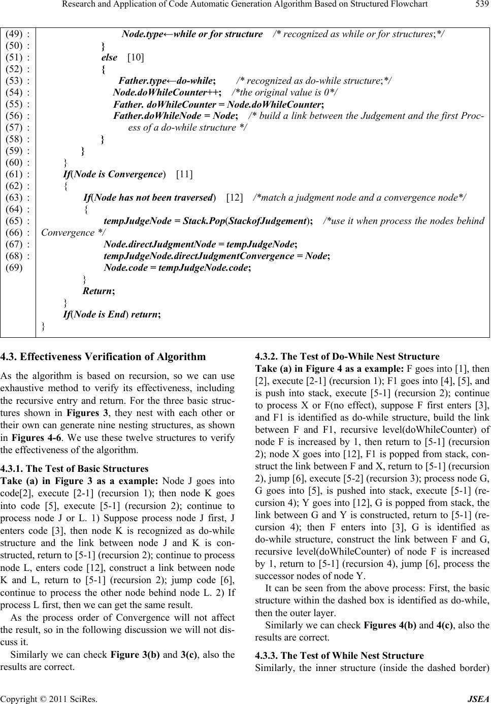 Research and Application of Code Automatic Generation Algorithm Based on Structured Flowchart539 (49) : (50) : (51) : (52) : (53) : (54) : (55) : (56) : (57) : (58) : (59) : (60) : (61) : (62) : (63) : (64) : (65) : (66) : (67) : (68) : (69) Node.type←while or for structure /* recognized as while or for structures;*/ } else [10] { Father.type←do-while; /* recognized as do-w hi l e struct u re;*/ Node.doWhileCounter++; /*the original value is 0*/ Father. doWhileCounter = Node.doWhileCounter; Father.doWhileNode = Node; /* build a link between th e Judgement and the first Proc - ess of a do-while structure */ } } } If(Node is Convergence) [11] { If(Node has not been traversed) [12] /*match a ju d gment node an d a convergenc e node*/ { tempJudgeNode = Stack.Pop(StackofJudgement); /*use it when process the nodes behind Converge n ce */ Node.directJudgmentNode = tempJudgeN ode; tempJudgeNode.directJudgmentConvergence = Node; Node.code = tempJudgeNode.code; } Return; } If(Node is End) return; } 4.3. Effectiveness Verification of Algorithm As the algorithm is based on recursion, so we can use exhaustive method to verify its effectiveness, including the recursive entry and return. For the three basic struc- tures shown in Figures 3, they nest with each other or their own can generate nine nesting structures, as shown in Figures 4-6. We use these twelve structures to verify the effectiveness of the algorithm. 4.3.1. The Test of Basic Structures Take (a) in Figure 3 as a example: Node J goes into code[2], execute [2-1] (recursion 1); then node K goes into code [5], execute [5-1] (recursion 2); continue to process node J or L. 1) Suppose process node J first, J enters code [3], then node K is recognized as do-while structure and the link between node J and K is con- structed, return to [5-1] (recursion 2); continue to process node L, enters code [12], construct a link between node K and L, return to [5-1] (recursion 2); jump code [6], continue to process the other node behind node L. 2) If process L first, then we can get the same result. As the process order of Convergence will not affect the result, so in the following discussion we will not dis- cuss it. Similarly we can check Figure 3(b) and 3(c), also the results are correct. 4.3.2. The Test of D o-W hi l e Nest Struct ure Take (a) in Figure 4 as a example: F goes into [1], then [2], ex ecute [2-1] (r ecursion 1) ; F1 goes into [4], [5], and is push into stack, execute [5-1] (recursion 2); continue to process X or F(no effect), suppose F first enters [3], and F1 is identified as do-while structure, build the link between F and F1, recursive level(doWhileCounter) of node F is increased by 1, then return to [5-1] (recursion 2); node X goes into [12], F1 is popped from stack, con- struct the link be tween F and X, retu rn to [5 -1] ( r ecu rsion 2), jump [6], execute [5-2 ] (recurs ion 3); process nod e G, G goes into [5], is pushed into stack, execute [5-1] (re- cursion 4); Y goes into [12], G is popped from stack, the link between G and Y is constructed, return to [5-1] (re- cursion 4); then F enters into [3], G is identified as do-while structure, construct the link between F and G, recursive level(doWhileCounter) of node F is increased by 1, return to [5-1] (recursion 4), jump [6], process the successor nodes of node Y. It can be seen from the above process: First, the basic structure within the dashed box is identified as do-while, then the outer layer. Similarly we can check Figures 4(b) and 4(c), also the results are correct. 4.3.3. The Test of While Nest Structure Similarly, the inner structure (inside the dashed border) Copyright © 2011 SciRes. JSEA 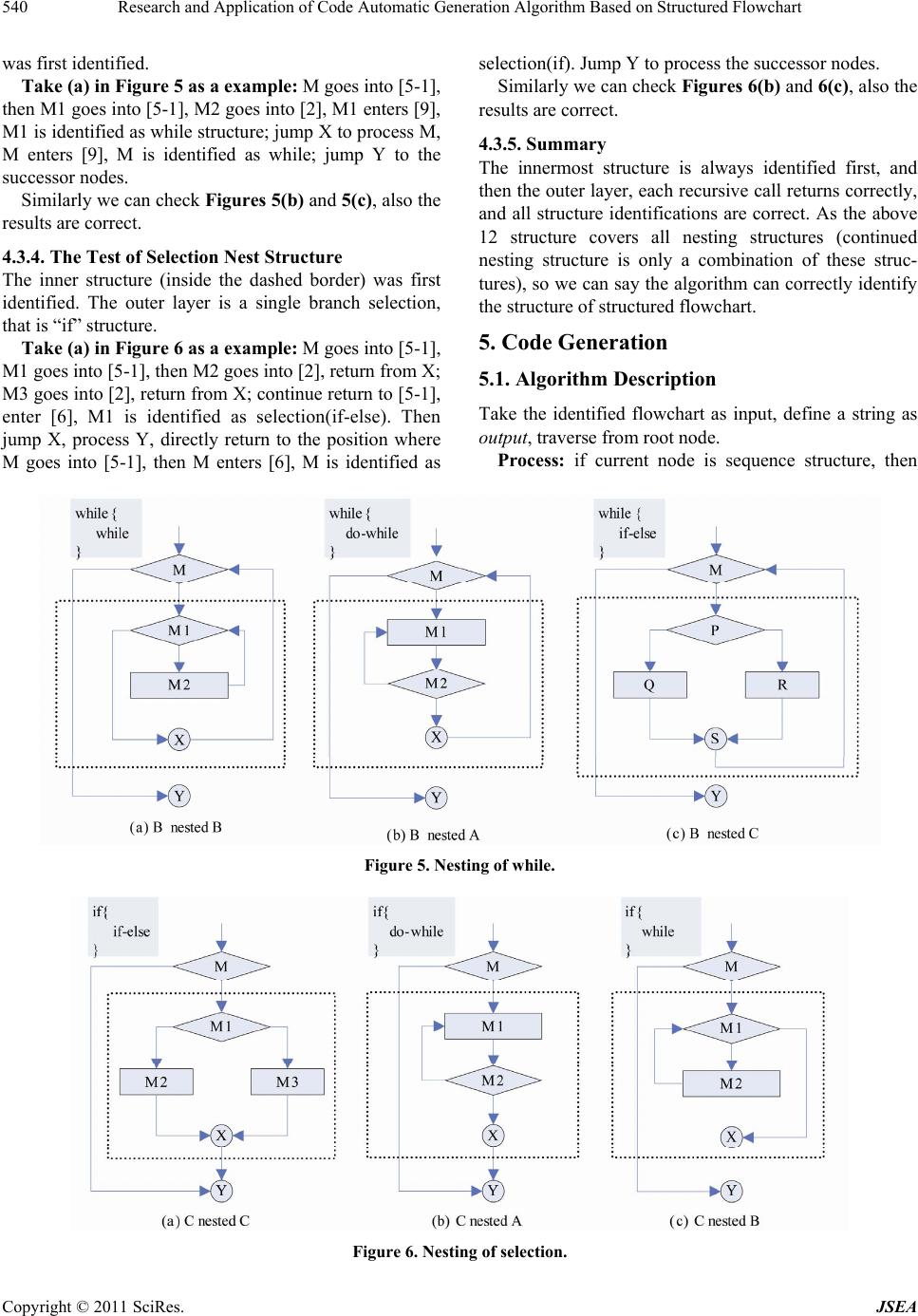 Research and Application of Code Automatic Generation Algorithm Based on Structured Flowchart Copyright © 2011 SciRes. JSEA 540 selection(if). Jump Y to process the successor nodes. was first identified. Take (a) in Figure 5 as a example: M goes into [5-1], then M1 goes into [5-1], M2 goes into [2], M1 enters [9 ], M1 is identified as while structur e; jump X to process M, M enters [9], M is identified as while; jump Y to the successor nodes. Similarly we can check Figures 6(b) and 6(c), also the results are correct. 4.3.5. Summa ry The innermost structure is always identified first, and then the outer layer, each recursive call returns correctly, and all structure identifications are correct. As the above 12 structure covers all nesting structures (continued nesting structure is only a combination of these struc- tures), so we can say the algorithm can correctly iden tify the structure of structured flowcha rt. Similarly we can check Figures 5(b) and 5(c), also the results are correct. 4.3.4. The Test of Selection Nest Structure The inner structure (inside the dashed border) was first identified. The outer layer is a single branch selection, that is “if” structure. 5. Code Generation Take (a) in Figure 6 as a example: M goes into [5-1], M1 goes into [5-1 ], th en M2 go es in to [2 ], return fr om X; M3 goes into [2 ], retur n from X; con tinue retu rn to [5 -1], enter [6], M1 is identified as selection(if-else). Then jump X, process Y, directly return to the position where M goes into [5-1], then M enters [6], M is identified as 5.1. Algorithm Description Take the identified flowchart as input, define a string as output, traverse from root node. Process: if current node is sequence structure, then Figure 5. Nesting of while. Figure 6. Nesting of selection. 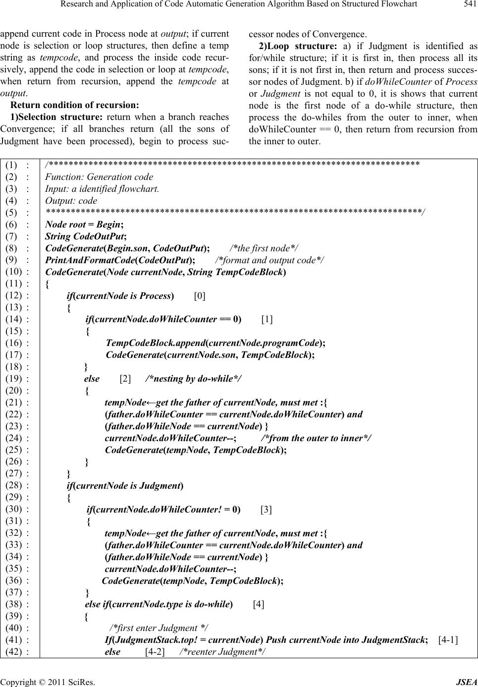 Research and Application of Code Automatic Generation Algorithm Based on Structured Flowchart541 append current code in Process node at output; if current node is selection or loop structures, then define a temp string as tempcode, and process the inside code recur- sively, append the code in selection or loop at tempcode, when return from recursion, append the tempcode at output. Return condition of recursion: 1)Selection structure: return when a branch reaches Convergence; if all branches return (all the sons of Judgment have been processed), begin to process suc- cessor nodes o f Co n vergence. 2)Loop structure: a) if Judgment is identified as for/while structure; if it is first in, then process all its sons; if it is not first in, then return and process succes- sor nodes of Judgment. b) if doWhileCounter of Process or Judgment is not equal to 0, it is shows that current node is the first node of a do-while structure, then process the do-whiles from the outer to inner, when doWhileCounter == 0, then return from recursion from the inn er to outer . (1) : (2) : (3) : (4) : (5) : (6) : (7) : (8) : (9) : (10) : (11) : (12) : (13) : (14) : (15) : (16) : (17) : (18) : (19) : (20) : (21) : (22) : (23) : (24) : (25) : (26) : (27) : (28) : (29) : (30) : (31) : (32) : (33) : (34) : (35) : (36) : (37) : (38) : (39) : (40) : (41) : (42) : /*************************************************************************** Function: Generati o n code Input: a identified flowchart. Output: code ************* ********* ********* ****** ********* ********* ********* ********* ***/ Node root = Begin; String CodeOutPut; CodeGenerate(Begin.son, CodeOutPut); /*the first node*/ PrintAndFormatCode(CodeOutPut); /*format and output code*/ CodeGenerate(Node currentNode, String TempCodeBlock) { if(currentNode is Process) [0] { if(currentNode.doWhileCounter == 0) [1] { TempCodeBlock.append(currentNode.programCode); CodeGenerate(currentNode.son, TempCodeBlock); } else [2] /*nesting by do-while*/ { tempNode←get the father of currentNode, must met :{ (father.doWhileCounter == currentNode.doWhileCounter) and (father.doWhileNode == currentNode) } currentNode.doWhileCounter--; /*from the outer to inner*/ CodeGenerate(tempNode, TempCodeBlock); } } if(currentNode is Judgment) { if(currentNode.doWhileCounter! = 0) [3] { tempNode←get the father of currentNode, must met :{ (father.doWhileCounter == currentNode.doWhileCounter) and (father.doWhileNode == currentNode) } currentNode.doWhileCounter--; CodeGenerate(tempNode, TempCodeBlock); } else if(currentNode.type is do-while) [4] { /*first enter Judgment */ If(JudgmentStack.top! = currentNode) Push currentNode into JudgmentStack; [4-1] else [4-2] /*reenter Judgment*/ Copyright © 2011 SciRes. JSEA 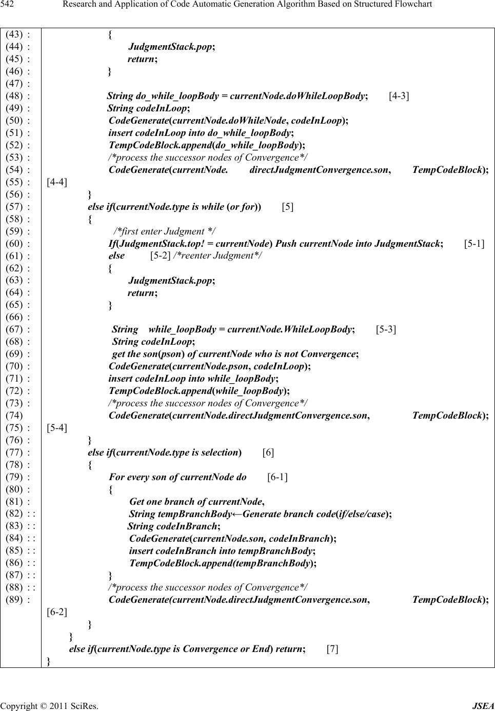 Research and Application of Code Automatic Generation Algorithm Based on Structured Flowchart 542 (43) : (44) : (45) : (46) : (47) : (48) : (49) : (50) : (51) : (52) : (53) : (54) : (55) : (56) : (57) : (58) : (59) : (60) : (61) : (62) : (63) : (64) : (65) : (66) : (67) : (68) : (69) : (70) : (71) : (72) : (73) : (74) (75) : (76) : (77) : (78) : (79) : (80) : (81) : (82) : : (83) : : (84) : : (85) : : (86) : : (87) : : (88) : : (89) : { JudgmentStack.pop; return; } String do_while_loopBody = currentNode.doWhileLoopBody; [4-3] String codeInLoop; CodeGenerate(currentNode.doWhileNode, codeInLoop); insert codeInLoop into do_while_loopBody; TempCodeBlock.append(do_while_loopBody); /*process the successor nodes of Convergence*/ CodeGenerate(currentNode. directJudgmentConvergence.son, TempCodeBlock); [4-4] } else if(currentNode.type is while (or for)) [5] { /*first enter Judgment */ If(JudgmentStack.top! = currentNode) Push currentNode into JudgmentStack; [5-1] e lse [5-2] /*reenter Judgment*/ { JudgmentStack.pop; return; } String while_loopBody = currentNode.WhileLoopBody; [5-3] String codeInLoop; get the son(pson) of currentNode who is not Convergence; CodeGenerate(currentNode.pson, codeInLoop); insert codeInLoop into while_loopBody; TempCodeBlock.append(while_loopBody); /*process the successor nodes of Convergence*/ CodeGenerate(currentNode.directJudgmentConvergence.son, TempCodeBlock); [5-4] } else if(currentNode.type is selection) [6] { For every son of currentNode do [6-1] { Get one branch of currentNode, String tempBranchBody←Generate branch code(if/else/case); String codeInBranch; CodeGenerate(currentNode.son, codeInBranch); insert codeInBranch into tempBranchBody; TempCodeBlock.append(tempBranchBody); } /*process the successor nodes of Convergence*/ CodeGenerate(currentNode.directJudgmentConvergence.son, TempCodeBlock); [6-2] } } else if(currentNode.type is Convergence or End) return; [7] } Copyright © 2011 SciRes. JSEA  Research and Application of Code Automatic Generation Algorithm Based on Structured Flowchart Copyright © 2011 SciRes. JSEA 543 5.2. Effectiveness Verification of Algorithm code; F enter [1], generate the loopbody code of F1; F1 goes into [4], [4-2], return to [4-2] where F1 calls Code- Generate, generate the inner full do-while code; Then execute [4-4], G goes in to [4-2 ] and r etu rn to [4-3 ] wher e G calls CodeGenerate, at this time codeInLoop contains the full code of inner do-while. At last generate the outer complete do-while code, execute [4-4] to process suc- cessor nodes. As the algorithm is based on recursion, so we can use exhaustive method to verify its effectiveness, including the recursive entry and return. We use those twelve structures to verify the effectiveness of the algorithm. The difference from structure identification algorithm is that the identification is from the inner to outer for nest structure, and generation is on the contrary. Similarly we can check the other nesting structures, also the results are correct. 5.2.1. Code G e nera ti on for Basic Structure Take (a) in Figure 3 as a example: J goes into [2], K goes into [4], [4-1], [4-3], then J enters [1], K enters [4], [4-2], return to CodeGenerate() of [1]; then return to CodeGenerate() of [4-3]. At this time codeInLoop has been generated, further the entire code of do-while is generated. Execute [4-4], continue to process successor nodes of Convergend. 5.2.3. Summa ry As the above 12 structure covers all nesting structures (continued nesting structure is only a combination of these structures), so we can say the algorithm can cor- rectly generate the code for structured identified flow- chart. 6. Integrated Development Platform Similarly we can check Figures 3(b) and 3(c), also the results are correct. We developed a integrated develop platform based on Eclipse platform and Graphical Editor Framework (GEF), including flowchart modeling and code automatic gen- eration, to verify the effectiveness of the proposed algo- rithms. 5.2.2. Code G e nera ti on for Nesting Structure Take (a) in Figure 4 as a example: F goes into [2], as F lies in two do-while structures, so it’s doWhileCounter is 2; G goes into [4], [4-1], execute [4-3], generate the out- ermost do-while framework code; F reenter [2], at this time doWhileCounter==1; then F1 goes into [4], [4-1], execute [4-3], generate the inner do-while framework We construct a model to test various complex nesting structures, including the case of sub-flowchart nest. As shown in Figure 7, there are totally five structures: Begin Judgement Judgement Judgement Judgement Judgement Sub-block Calling code code code 0 123 End Figure 7. An example of flowchart in integrate d development platform. 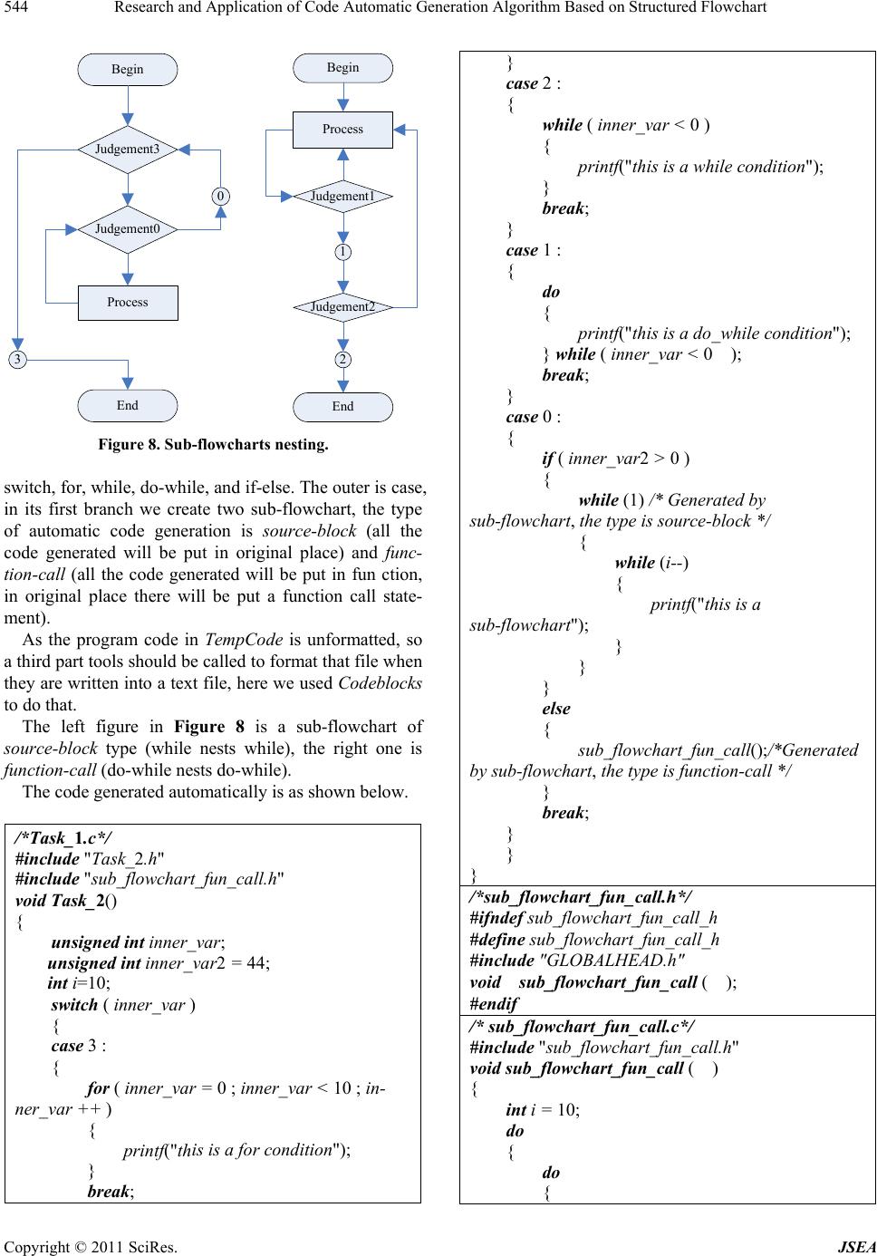 Research and Application of Code Automatic Generation Algorithm Based on Structured Flowchart 544 Begin Judgement3 Judgement0 Process 3 End 0 Begin Process Judgement1 1 Judgement2 2 End Figure 8. Sub-flowcharts nesting. switch, for, while, do-while, and if-else. The outer is case, in its first branch we create two sub-flowchart, the type of automatic code generation is source-block (all the code generated will be put in original place) and func- tion-ca ll (all the code generated will be put in fun ction, in original place there will be put a function call state- ment). As the program code in TempCode is unformatted, so a third part tools should be called to format that file wh en they are written into a tex t file, here we used Codeblocks to do that. The left figure in Figure 8 is a sub-flowchart of source-block type (while nests while), the right one is function- call (do-while nests do-while). The code generated auto matically is as shown b e low. /*Task_1.c*/ #include "Task_2.h" #include "sub_flowchart_fun_call.h" void Task_2() { unsigned int inner_var; unsigned int inner_var2 = 44; int i=10; switch ( inner_var ) { case 3 : { for ( inner_var = 0 ; inner_var < 10 ; in- ner_v ar ++ ) { printf("this is a for condition") ; } break; } case 2 : { while ( inner_var < 0 ) { printf("this is a while condition"); } break; } case 1 : { do { printf("this is a do_while condition"); } while ( inner_var < 0 ); break; } case 0 : { if ( inner_var2 > 0 ) { while (1) /* Generated by sub-flowchart, the type is source-block */ { while (i--) { printf("this is a sub-flowchart") ; } } } else { sub_flowchart_fun_call();/*Generated by sub-flowchart, the type is function-call */ } break; } } } /*sub_flowchart_fun_call.h*/ #ifndef sub_flowchart_fun_call_h #define sub_flowchart_fun_call_h #include "G LOBAL HE AD.h " void sub_flowchart_fun_call ( ); #endif /* sub_flowchart_fun_call.c*/ #include "sub_flowchart_fun_call.h" void sub_flowchart_fun_call ( ) { int i = 10; do { do { Copyright © 2011 SciRes. JSEA  Research and Application of Code Automatic Generation Algorithm Based on Structured Flowchart545 printf("this is sub_flo wchart function call"); } while (i--); } while (1); } 7. Conclusions We proposed a structure identification algorithm for structured flowchart. The effectiveness of the proposed algorithm is checked using exhaustive method, i.e., twelve structures can be identified, then a algorithm can be used to generate code from identified flowchart using recursion algorithm. The technologies and algorithms are used in a integrated development platform, we develop a weapon system based on the platform to verify the ef fec- tiveness of the proposed algorithm. REFERENCES [1] T. Zhang, Y. Zhang, X.-F. Yu, et al., “MDA Based De- sign Patterns Modeling and Model Transformation,” Journal of Software, Vol. 19, No. 9, 2008, pp. 2203-2217. [2] R.-F. Lv, G. Wang, X.-X. Wen, et al., “Process Modeling Method of Calculation Independent Model Level Based on MDA,” Computer Integrated Manufacturing Systems, Vol. 14, No. 5, 2008, pp. 868-874. [3] S. Needham, “OMG Unified Modeling Language Speci- fication,” Object Management Group, 2003, pp. 275-293. http://www.digilife.be/quickreferences/Books/OMG%20 UML%20Specification%201.4.pdf [4] Z. K. Zhao, Q. J. Sheng and Z. Z. Shi, “An Execution Semantics of UML Activity View for Workflow Model- ing,” Journal of Computer Research and Development, Vol.42, No. 2, 2005, pp. 300-307. [5] R. Eshuis and R. Wieringal, “A Formal Semantics for UML Activity Diagrams,” Tech Report, University of Twente, 2001, pp. 201-204. [6] H. Jiang, D. Lin and X. R. Xie, “The Formal Semantics of UML State Machine,” Journal of Software, Vol. 13, No. 12, 2002, pp. 2244-2250. [7] D. Harel, “Statecharts: A Visual Formalism for Complex Systems,” Science of Computer Programming, 2007. [8] J.-L. Shen, L.-Z. Wa ng, X.-D. Li, et al., “An Approach to Generate Scenario Test Cases Based on UML Sequence Diagrams,” Computer Science, Vol. 31, No. 8, 2004, pp. 1-6. [9] S. Raman, N. Sivashankar and W. Stuart, “HIL Simula- tors for Powertrain Control System Software Develop- ment,” American Controls Conference, St. Louis, Mis- souri, USA, 2009, pp. 23-32. [10] S. Sendall and W. Kozaczynski, “Model Transformation: The Heart and Soul of Model-Driven Software Develop- ment,” IEEE Software, Vol. 9, 2003, pp. 42-45. doi:10.1109/MS.2003.1231150 [11] H. Dakhore and A. Mahajan, “Generation of C-Code Using XML Parser,” http://www.rimtengg.com/iscet/proceedings/pdfs/advcom p/ 149.pdf [12] M. C. Carlisle, T. A. Wilson, J. W. Humphries, et al., “Raptor: Introducing Programming to Non-majors with Flowcharts,” Journal of Computing Sciences in Colleges, Vol. 19, No. 4, 2004, pp. 1-6. [13] T. Watts, “The SFC Editor: A Graphical Tool for Algo- rithm Development,” Journal of Computing in Small Col- leges, Vol. 20, No. 2, 2004, pp. 73-85. [14] K. Charntaweekhun and S. Wangsiripitak, “Visual Pro- gramming Using Flowchart,” International Symposium on Communications and Information Technologies, ISCIT '06, 20 September - 18 October 2006, pp. 1062-1065. [15] I. Nassi and B. Shneiderman, “Flowchart Techniques for Structured Programming,” ACM SIGPLAN Notices, Vol. 8, No. 8, 1973, pp. 12-26. doi:10.1145/953349.953350 [16] J. F. Gimpel, “Contour: A Method of Preparing Struc- tured Flowcharts,” ACM SIGPLAN Notices, Vol. 15, No. 10, 1980, pp. 35-41. Copyright © 2011 SciRes. JSEA
|