Paper Menu >>
Journal Menu >>
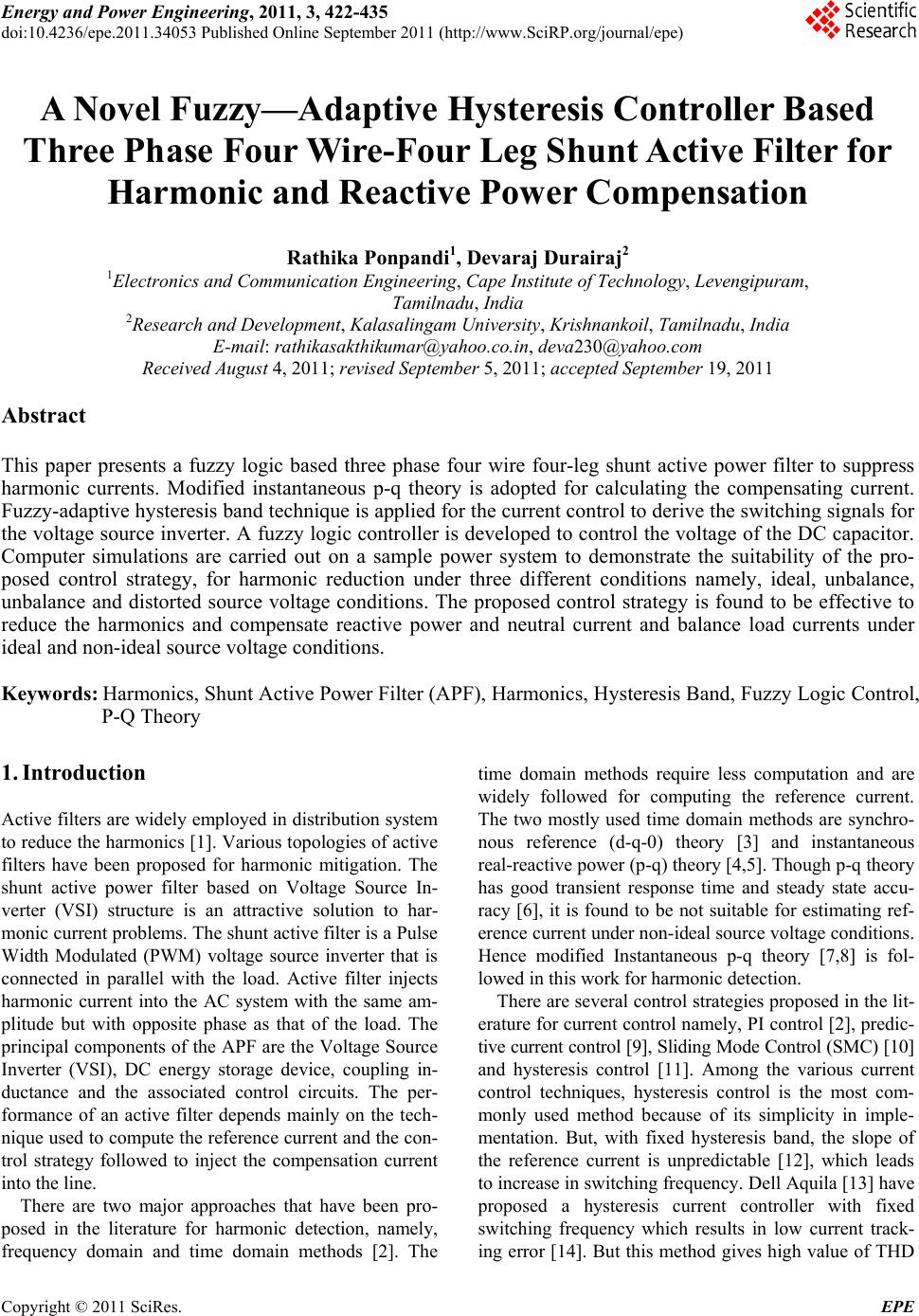 Energy and Power En gi neering, 2011, 3, 422-435 doi:10.4236/epe.2011.34053 Published Online September 2011 (http://www.SciRP.org/journal/epe) Copyright © 2011 SciRes. EPE A Novel Fuzzy—Adaptive Hysteresis Controller Based Three Phase Four Wire -Four Leg Shunt Active Filter for Harmonic and Reactive Power Compensation Rathika Ponpandi1, Devaraj Durairaj2 1Electronics and Communication Engineering, Cape Institute of Technology, Levengipuram, Tamilnadu, India 2Research and Development, Kalasalingam University, Krishnankoil, Tamilnadu, India E-mail: rathikasakthikumar@yahoo.co.in, deva230@yahoo.com Received August 4, 2011; revised September 5, 2011; accepted September 19, 2011 Abstract This paper presents a fuzzy logic based three phase four wire four-leg shunt active power filter to suppress harmonic currents. Modified instantaneous p-q theory is adopted for calculating the compensating current. Fuzzy-adaptive hysteresis band technique is applied for the current control to derive the switching signals for the voltage source inverter. A fuzzy logic controller is developed to control the voltage of the DC capacitor. Computer simulations are carried out on a sample power system to demonstrate the suitability of the pro- posed control strategy, for harmonic reduction under three different conditions namely, ideal, unbalance, unbalance and distorted source voltage conditions. The proposed control strategy is found to be effective to reduce the harmonics and compensate reactive power and neutral current and balance load currents under ideal and non-ideal source voltage conditions. Keywords: Harmonics, Shunt Active Power Filter (APF), Harmonics, Hysteresis Band, Fuzzy Logic Control, P-Q Theory 1. Introduction Active filters are widely employed in distribution system to reduce the harmonics [1]. Various topologies of active filters have been proposed for harmonic mitigation. The shunt active power filter based on Voltage Source In- verter (VSI) structure is an attractive solution to har- monic current problems. The shunt active filter is a Pulse Width Modulated (PWM) voltage source inverter that is connected in parallel with the load. Active filter injects harmonic current into the AC system with the same am- plitude but with opposite phase as that of the load. The principal components of the APF are the Voltage Source Inverter (VSI), DC energy storage device, coupling in- ductance and the associated control circuits. The per- formance of an active filter depends mainly on the tech- nique used to compute the reference current and the con- trol strategy followed to inject the compensation current into the line. There are two major approaches that have been pro- posed in the literature for harmonic detection, namely, frequency domain and time domain methods [2]. The time domain methods require less computation and are widely followed for computing the reference current. The two mostly used time domain methods are synchro- nous reference (d-q-0) theory [3] and instantaneous real-reactive power (p-q) theory [4,5]. Though p-q theory has good transient response time and steady state accu- racy [6], it is found to be not suitable for estimating ref- erence current under non-ideal source voltage conditions. Hence modified Instantaneous p-q theory [7,8] is fol- lowed in this work for harmonic detection. There are several control strategies proposed in the lit- erature for current control namely, PI control [2], predic- tive current control [9], Sliding Mode Control (SMC) [10] and hysteresis control [11]. Among the various current control techniques, hysteresis control is the most com- monly used method because of its simplicity in imple- mentation. But, with fixed hysteresis band, the slope of the reference current is unpredictable [12], which leads to increase in switching frequency. Dell Aquila [13] have proposed a hysteresis current controller with fixed switching frequency which results in low current track- ing error [14]. But this method gives high value of THD 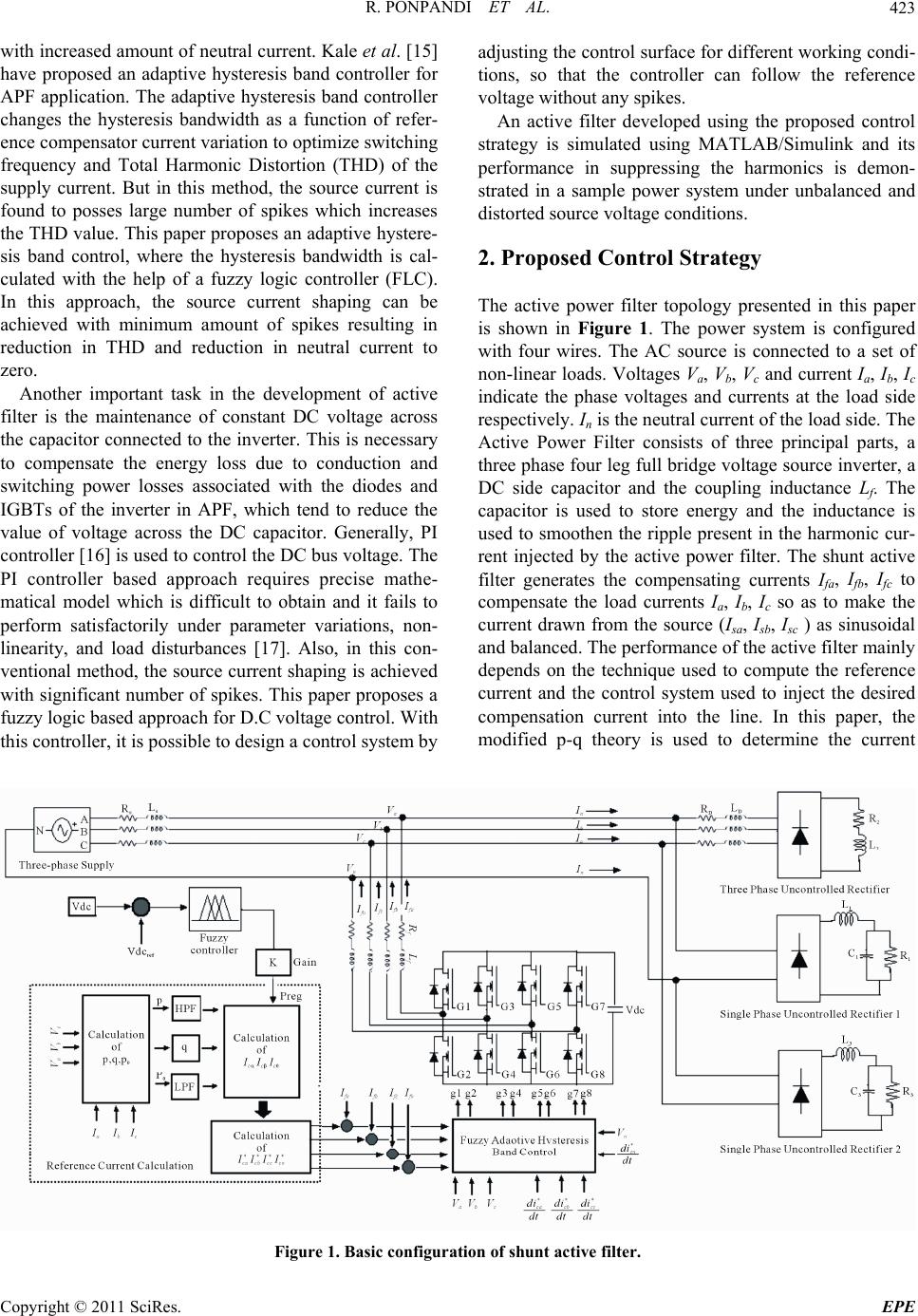 R. PONPANDI ET AL.423 with increased amount of neutral current. Kale et al. [15] have proposed an adaptive hysteresis band controller for APF application. The adaptive hysteresis band controller changes the hysteresis bandwidth as a function of refer- ence compensator current variation to optimize switching frequency and Total Harmonic Distortion (THD) of the supply current. But in this method, the source current is found to posses large number of spikes which increases the THD value. This paper proposes an adaptive hystere- sis band control, where the hysteresis bandwidth is cal- culated with the help of a fuzzy logic controller (FLC). In this approach, the source current shaping can be achieved with minimum amount of spikes resulting in reduction in THD and reduction in neutral current to zero. Another important task in the development of active filter is the maintenance of constant DC voltage across the capacitor connected to the inverter. This is necessary to compensate the energy loss due to conduction and switching power losses associated with the diodes and IGBTs of the inverter in APF, which tend to reduce the value of voltage across the DC capacitor. Generally, PI controller [16] is used to control the DC bus voltage. The PI controller based approach requires precise mathe- matical model which is difficult to obtain and it fails to perform satisfactorily under parameter variations, non- linearity, and load disturbances [17]. Also, in this con- ventional method, the source current shaping is achieved with significant number of spikes. This paper proposes a fuzzy logic based approach for D.C voltage control. With this controller, it is possible to design a control system by adjusting the control surface for different working condi- tions, so that the controller can follow the reference voltage without any spikes. An active filter developed using the proposed control strategy is simulated using MATLAB/Simulink and its performance in suppressing the harmonics is demon- strated in a sample power system under unbalanced and distorted source voltage conditions. 2. Proposed Control Strategy The active power filter topology presented in this paper is shown in Figure 1. The power system is configured with four wires. The AC source is connected to a set of non-linear loads. Voltages Va, Vb, Vc and current Ia, Ib, Ic indicate the phase voltages and currents at the load side respectively. In is the neutral current of the load side. The Active Power Filter consists of three principal parts, a three phase four leg full bridge voltage source inverter, a DC side capacitor and the coupling inductance Lf. The capacitor is used to store energy and the inductance is used to smoothen the ripple present in the harmonic cur- rent injected by the active power filter. The shunt active filter generates the compensating currents Ifa, Ifb, Ifc to compensate the load currents Ia, Ib, Ic so as to make the current drawn from the source (Isa, Isb, Isc ) as sinusoidal and balanced. The performance of the active filter mainly depends on the technique used to compute the reference current and the control system used to inject the desired compensation current into the line. In this paper, the modified p-q theory is used to determine the current Figure 1. Basic configuration of shunt active filter. Copyright © 2011 SciRes. EPE 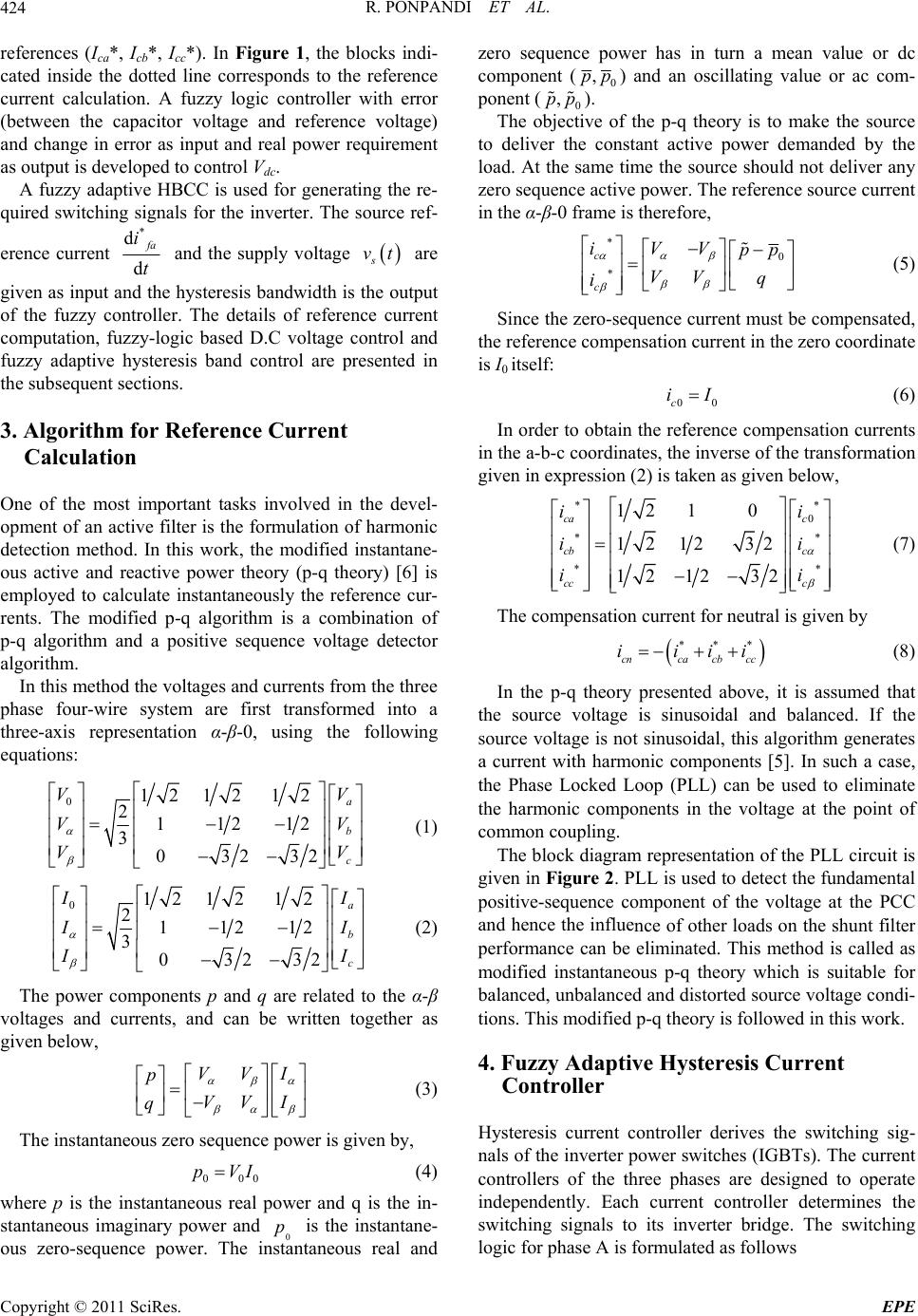 R. PONPANDI ET AL. 424 references (Ica*, Icb*, Icc*). In Figure 1, the blocks indi- cated inside the dotted line corresponds to the reference er. The source ref- current calculation. A fuzzy logic controller with error (between the capacitor voltage and reference voltage) and change in error as input and real power requirement as output is developed to control Vdc. A fuzzy adaptive HBCC is used for generating the re- quired switching signals for the invert erence current * d d f a i t and the supply voltage s vt are given as input and te hysteresis bandwidth is tutput hhe o of the fuzzy controller. The details of reference current ference Current Onportant tasks involved in the devel- opment of an active filter is the formulation of harmonic -wire system are first transformed into a th computation, fuzzy-logic based D.C voltage control and fuzzy adaptive hysteresis band control are presented in the subsequent sections. 3. Algorithm for Re Calculation e of the most im detection method. In this work, the modified instantane- ous active and reactive power theory (p-q theory) [6] is employed to calculate instantaneously the reference cur- rents. The modified p-q algorithm is a combination of p-q algorithm and a positive sequence voltage detector algorithm. In this method the voltages and currents from the three phase four ree-axis representation α-β-0, using the following equations: 0 V 12 1212 211 212 3 03232 a b c V VV VV (1) 012 1212 211212 3 03232 a b c I I I I I I (2) The power components p and q are related to the α-β voltages and currents, and can be written together as given below, I VV p VV I q (3) The instantaneous zero sequence pow ) where p is the instantaneous real stantaneous imaginary power and zero sequence power has in turn a mean value or dc component ( er is given by, 000 pVI (4 power and q is the in- p is the instantane- 0 ous zero-sequence power. The instantaneous real and 0 ,pp) and an oscillating value or ac com- me ce active power. The reference source current in ponent (0 ,pp ). The objective of the p-q theory is to make the source to deliver the constant active power demanded by the load. At the s time the source should not deliver any zero sequ a en the α-β-0 frame is therefore, * 0 * c c iVV pp VV q i nt must be compensated, the refeompensation current in the is I0 (5) Since the zero-sequence curre rence c itself: zero coordinate 00c iI (6) In order to obtain the reference compensation currents in the a-b-c co n expres ordinates, the inverse of the transformation given ision (2) is taken as given below, ** 0 ** ** 12 10 12 1232 12 1232 ca c cb c ii ii ii cc c (7) The censation current for neutral is giveompn by *** cnca cb cc iiii (8) that th the source is not sinusoidal, this a curreharmonic components [5]. In such a case, th nce of other loads on the shunt filter pe ing sig- current co three phases are designed to operate indepetly. Each current controller determines the In the p-q theory presented above, it is assumed e source voltage is sinusoidal and balanced. If voltage nt with nden algorithm generates e Phase Locked Loop (PLL) can be used to eliminate the harmonic components in the voltage at the point of common coupling. The block diagram representation of the PLL circuit is given in Figure 2. PLL is used to detect the fundamental positive-sequence component of the voltage at the PCC and hence the influe rformance can be eliminated. This method is called as modified instantaneous p-q theory which is suitable for balanced, unbalanced and distorted source voltage condi- tions. This modified p-q theory is followed in this work. 4. Fuzzy Adaptive Hysteresis Current Controller Hysteresis current controller derives the switch nals of the inverter power switches (IGBTs). The ntrollers of the switching signals to its inverter bridge. The switching logic for phase A is formulated as follows Copyright © 2011 SciRes. EPE  R. PONPANDI ET AL.425 V na V nb V nc sin(ωt) PI-Controller sin(ωt-2 π/3) 1/s sin(ωt-π/2) sin(ωt-π/2-2 π/3) sin(ωt-π/2+2 π/3) X X V ab V cb ω ωt Σ Figure 2. Phase locked loop circuit. If upper switch is O itc a similar manne derived. ctor up and down so that it fo * fa fa iiHB h is ON. FF and lower sw If upper switch is ON and lower switch is OFF. * fa fa iiHB In r, the switching logic for devices in phase B and C are The switches are controlled asynchronously to ramp the current through the indu llows the reference. The current ramping up and down between the two limits is illustrated in Figure 3. When the current through the inductor exceeds the upper hys- teresis limit a negative voltage is applied by the inverter to the inductor. This causes the current in the inductor to decrease. Once the current reaches the lower hysteresis limit a positive voltage is applied by the inverter to the inductor and this causes the current to increase and the cycle repeats. The bandwidth of the hysteresis current controller is given by [10], 2* 9d 1, 6d ffa s1,2,3 j mf dc f Li vt j fLV Lt (9) dc V HB where m f is the modulation frequency, * f a i is the source reference current, * d d f a i t represents its slope, f L is the decoupling inductance of the active power is me dra bhree ity of filter, is the DC bus voltage and s vt the sup- dc V ply voltage. The fixed hysteresis bandthod explained has the wbacks of variable switching frequency, heavy inter- ferenceetween the phases in case of tphase active filter with isolated neutral and irregularthe modula- tion pulse position [15]. These problems result in high current ripples, acoustic noise and difficulty in designing input filter. To overcome these difficulties, this paper presents an adaptive hysteresis band current control technique in which the hysteresis bandwidth is deter- mined by the fuzzy logic controller. Fuzzy control is based on the principles of fuzzy logic [18]. It is a non-linear control method, which attempts to apply the expert knowledge of an experienced user to the design of a controller. Fuzzy modeling provides the abil- ity to linguistically specify approximate relationships between the input and desired output. The relationships are represented by a set of fuzzy If-then rules in which the antecedent is an approximate representation of the state of the system and the consequent provides a range of potential responses. In this work, the fuzzy logic controller is used to de- termine the hysteresis band width according to the sup- ply voltage and the rate of change of filter current. From Equation (7), it is noted that the hysteresis band- width is a function of * d d f a i t and s vt. Hence, these vari- ables are taken as input to the fuzzy controller, an d the hy variables namely, NL (Negative Large), NM (Negative steresis band width (HB) is the output. Five linguistic Figure 3. Waveform of hysteresis current control operation waveform. Copyright © 2011 SciRes. EPE  R. PONPANDI ET AL. 426 Medium), EZ (Zero), PM (Positive Medium) and PL ssignthe (Positive Large) are aed to input and five lin- guistic variables, namely PVL (Positive Very Low), PL (Positive Low), PB (Positive Big) and PVB (Positive Very Big) are assigned to output variables. The mem- bership functions of the input and output variables are shown in Figure 4. The fuzzy rule base with 25 rules is given in Table 1. (a) (b) (c) Figure 4. Membership functions for the input variables (a) s vt, (b) * d d f a i tand (c)output variable HB. Table 1. Fuzzy rule baor current controller. se f * dfa i NL NM EZ dtPM PL s vt NL PB PM PM PM PB NM PB PM PL PM PB EZ PM PB PM PL PM PB PVB PM PVLPM PVL PL PB PM PM PM PB In this approach swng uen keon- stant and the currentd r- inetter stabilityn paetea- ti 5. Fuzzy-Logic Based DC Voltage Control ower necessary to compensate the losses of the by f , theitchifreqcy ispt c error is and i appreciably re sensitiv duce ram ensu r varig bity to on. The DC side of the inverter is connected to a capacitor. The capacitor provides a constant DC voltage and the real p system. In the steady state, the real power supplied the source should be equal to the real power demand o the load plus a small power to compensate the losses in the active filter. Hence, it is necessary to maintain the DC capacitor voltage at a reference value. In this work a fuzzy logic controller is developed to maintain the con- stant voltage across the capacitor. The capacitor voltage deviation and its derivative are taken as the inputs of the FLC and the real power (Preg) requirement for voltage regulation is taken as the output. Both input and output variables are represented by seven linguistic variables, namely, NL (Negative Large), NM (Negative Medium), NS ( Negative Small), ZE (Zero), PS (Positive Small), PM (Positive Medium) and PL ( Positive large). Figure 5 shows the membership func- tions of the input and output variables. The fuzzy if-then rules formed for controlling the DC voltage are given in Table 2. Figure 5. Membership function for the input and output variable. Table 2. Fuzzy rule base for voltage control. eNL NMNS ZE PS PMPL de NL NL NL NL NL NM NS ZE NM PS NS NL NL NMNS ZE PS PM PL NL NM NS ZE PS PM PL NL NL NL NM NS ZE ZE NL NM NS ZE PS PM PL PS NMNS ZE PS PM PL PL PM NS ZE PS PM PL PL PL Copyright © 2011 SciRes. EPE  R. PONPANDI ET AL. Copyright © 2011 SciRes. EPE 427 6.uon su Thctire thtail the simul carried oudemtrae etivs o prsed- troatefor ac fforrm ct filtering, reactive r compoad current- an anuturreli ss t the analysis. The test upply connected to a set of non-linear loads namely, a three-phase uncon- ed in this case. The TH Figure 10(a). The Simlati Relts is seon psentse des ofation t to onste thffecenesf theopo con l strgy the powe tiveilter ensation, l haonicurren bal cingd neral cent mination. Figure 6how monic Distortion (THD) of the distorted three-phase line currents (Ia, Ib & Ic) are 18.74%, 25.74% and 50.42% respectively. The THD level of neutral current is 87.29%.The harmonic spectrum of phase and neutral currents are shown in Figure 7(c). Next, the active filter is simulated using the proposed control strategy and connected in parallel with the load. Figure 8 shows the waveforms obtainthe test system used to carry ou system consists of a three phase sD of current in phase A, B and C has reduced to 2.72%, 3.66% and 3.64% respectively. As shown in Figures 8(b) and (d) after the installation of the filter, the three phase source current is balanced and sinusoidal and it is in phase with the supply voltage. The harmonic spectrum of the source current is shown in Figure 8(c). As shown in Figure 9(a), the neutral current has been completely eliminated. The instantaneous real and reac- tive power supplied from the source in phase A is shown in Figure 9(b). From the figure it is found, that the source delivers constant real power and zero reactive power to the load which indicates that the source side power factor is maintained at unity. Figure 9(c) shows the constant voltage (1500 V) maintained by the fuzzy logic controller across the capacitor. Case B: Unbalanced Sou rce Voltage In this case, the source voltage is made unbalanced from 0.4 sec to 0.5 sec as shown in trolled rectifier with RL load and two single-phase un- controlled rectifiers with RLC load. The active filter is connected to the test system through an inductor L. The values of the circuit elements used in the simulation are given in Appendix A. MATLAB/SIMULINK is used to simulate the test system and the proposed shunt active filter. The simulation was conducted under three differ- ent conditions, namely, ideal source voltage, unbalanced source voltage and unbalanced-distorted source condi- tions. The comprehensive simulation results are pre- sented below. Case A: Ideal Source Voltage First the system is simulated with ideal source voltage and without any filter. The three phase source current waveform in this case is shown in Figure 7(a). Figure 7(b) shows neutral current waveform. The Total har- Figure 6. Test system.  R. PONPANDI ET AL. 428 (a) (b) (c) Figure 7. Distorted Phase and Neutral current and harmonic spectrum. (a) Distorted three phase source current; (b) Nautral current; (c) Harmonic spectrum of phase and netural current. (a) (b) (c) (d) Figure 8. Harmonic cur rent filtering under ideal supply voltage conditions with fuzzy-adaptive HBCC technique. (a) Source voltage; (b) Source current; (c) Harmonic spectrum of source current; (d) Source voltage and source current. Copyright © 2011 SciRes. EPE  R. PONPANDI ET AL.429 (a) (b) (c) Figure 9. Reactive and ne utral current compensation under id eal supply voltage conditions with fuzzy-adaptive HBCC tech- nique. (a) Nautral current; (b) Instantaneous real and reactive power; (c) Voltage across the capacitor. (a) (b) Figure 10. Unbalanced source voltage and load current. (a) Unbalanced source voltage; (b) Unbalance load current. Copyright © 2011 SciRes. EPE  R. PONPANDI ET AL. Copyright © 2011 SciRes. EPE 430 unbalance is due to the voltage deviation in phase A. The unbalanced load current is shown in Figure 10(b). In the absence of the active filter, the THD level of the three phase currents and neutral current between the time pe- riod 0.4 sec to 0.5 sec are 20.91%, 25.74%, 50.92% and 92.06% respectively. The source current waveform and its harmonic spectrum after installing the active filter with modified p-q theory and the proposed control strat- egy are given in Figure 11. In this case, the THD level C respectively. For comparison, the filter was simulated with general p-q theory for reference current calculation and the compensated current is shown in Figure 12. Since the compensation current references have nega- tive-sequence component, the three phase compensated source current is not sinusoidal with general p-q theory. Also in this case, the THD value of source current after compensation exceeds the IEEE standard limit as shown in Table 3. This shows that the general p-q theory is not has reduced to 2.9%, 3.7% and 3.66% in phase A, B and suitable for compensation under unbalanced source (a) (b) (c) (d) Figure 11. Harmonic current filtering under unbalanced supply voltage conditions with fuzzy-adaptive hbcc technique. (a) Unbalanced source voltage; (b) Source current; (c) Harmonic spectrum of source current (THD for 0.4 to 0.5 sec); (d) Neu- tral curren t .  R. PONPANDI ET AL.431 (a) (b) Figure 12. Harmonic current filtering using general p-q theory. (a) Load current; (b) Harmonic spectrum of load current (THD for 0.4 sec to 0.5 sec). Table 3. Detailed summary of source current and their THD under unbalanced source voltage. Total Harmonic Distortion (THD) (%) Without Filter General p-q theory Modified p-q theory Three Phase Balanced Voltage (t > 0.5 sec) Unbalanced Voltage (0.4 sec < t > 0.5) Balanced Voltage (t > 0.5 sec) Unbalanced Voltage (0.4 sec < t > 0.5) Balanced Voltage (t > 0.5 sec) Unbalanced Voltage (0.4 sec < t > 0.5) Phase A 18.74 20.91 3.07 13.65 2.72 2.9 Phase B 25.74 25.74 4.5 11.49 3.66 3.7 Phase C 50.42 50.92 3.8 15.86 3.64 3.66 three phase source voltages are unbalanced and distorted, source voltage contains negative sequence component and harmonic voltage components. The dis- torted and unbalanced source voltage, source current and its harmonic spectrum and neural line current before the installation of the active filter are shown in Figures 13(a)- (d). Next, the active filter is simulated with modi- fied p-q theory for reference current calculation and with proposed control strategy and connected in parallel with the load. The simulation results are shown in Figure 14. From the figure it is evident that three phase source cur- rents are balanced and sinusoidal after the installation of and the source side power factor is maintained at unity. The summary of source currents and their THD level in each phase before and after filtering are given in Table 4. For comparison, the filter was simulated with fixed HBCC technique and the source current waveform along with its harmonic spectrum is shown in Figure 15. Per- formance comparison of the filter with fixed hysteresis band and fuzzy adaptive control strategies is given in Table 5. From the table it is observed that the proposed current control technique performs better than the fixed hysteresis current control technique in reducing the har- monics. voltage conditions. Case C: Unbalanced-Distorted Source Voltage When the the filter. Further, it is found that the source delivers constant real power and zero reactive power to the load Copyright © 2011 SciRes. EPE  R. PONPANDI ET AL. 432 7. Conclusions This paper has presented a fuzzy logic based approach for developing the active filter for three-phase four-wire distribution system. Modified p-q theory was employed for effectively computing the reference current under non-ideal source voltage conditions. The active filter was simulated using MATLAB/Simulink and the perform- ance was analyzed in a sample power system with a source and set of non-linear loads. The simulation results show that the proposed technique is effective in current harmonic filtering, reactive power compensation, neutral current elimination under unbalanced load and non-ideal source voltage conditions. Further the proposed tech- (a) (b) (c) tage condition. (a) Unbalanced and distor ted source voltage ; d) Harmo (d) vol t; (nic spectrum of source current. Figure 13. Waveforms under unbalanced and distorted source (b) Unbalance and distorted source voltage; (c) Neutral curren Copyright © 2011 SciRes. EPE  R. PONPANDI ET AL.433 (a) (b) (c) Figure 14. Harmonic current filtering under unbalanced and distorted supply voltage conditions. (a) Source current; (b Harmonic spectrum of source current; (c) Neurral current. ) (a) (b) Figure 15. Harmonic current filtering under ideal supply voltage conditions with fixed HBCC technique. (a) Source current; (b) Harmonic spectrum of source current. Copyright © 2011 SciRes. EPE  R. PONPANDI ET AL. Copyright © 2011 SciRes. EPE 434 Table 4. Summary of source current THD. THD (%) Three Phases Without Filter With Filter Phase A 26.35 3.38 Phase B 25.6 4.5 Phase C 61.2 4.6 Neutral 98.2 - Table 5. Summary of source current THD for various con- trol strategies. THD (%) Voltage Control Current Control Phase A Phase B Phase C Without Filter 18.74 25.74 50.42 Fuzzy Fixed Hysteresis 3.4 4.3 4.5 Fuzzy Fuzzy-Adaptive Hysteresis 2.72 3.6 3.6 nique has quick response time and it keeps the switching frequency nearly constant with good quality of filtering. 8. References [1] B. Singh, K. Al Haddad and A. Chandra, “A Review of Active Filters for Power Quality Improvement,” IEEE Trans on Industrial Electronics, Vol. 46, No. 5, October 1999, pp. 960-970. doi:10.1109/41.793345 [2] L. Asiminoaei, Fr. Blaabjerg and S. Hansen, “Evaluation of Harmonic Detection Methods for Active Power Filter Applications,” Applied Power Electronics Conference, Vol. 1, March 2005, pp. 635-641. [3] K. G. Firouzjah, A. Sheikholeslami, M. R. Karami-Mol- laei and F. Heydari, “A Predictive Current Control method for Shunt Active Filter with Windowing Based Wavelet Transform in Harmonic Detection,” Simulation Modelling Practice and Theory, Vol. 17, No. 1, 2009, pp. 883-896. doi:10.1016/j.simpat.2009.02.008 [4] L. S Czarnecki, “On Some Misinterpretations of the In- stantaneous Reactive Power p-q Theory,” IEEE Transac- tion on Power Electronics, Vol. 19, No. 3, 2003, pp. 828-836. [5] J. Afonso, C. Couto and J. Martins, “Ative Filters with Control Based on the p-q Theory,” IEEE Industrial Elec- tronics Society Newsletter, Vol. 47, No. 3, 2000, pp. 5-10. [6] Z. Salam, T. P. Cheng and A. Jusoh, “Harmonics Mitiga- tion Using Active Power Filter: A Technological Re- view,” Elekrika, Vol. 8, No. 2, 2006, pp. 17-26. [7] H. Akagi, E. H. Watanabe and M. Aredes, “The P-Q The- ory for Active Fiter Control: Some Problems and Solu- tions,” Revista Controle & Automacao, Vol. 15, No. 1, 2004, pp. 945-970. [8] H. Abaali, M. T. Lamchich and M. Raoufi, “The Three Phase Shunt Active Fiters for the Harmonics Compensa- tion under Distorted and Unbalanced Mains Voltage Conditions,” IEEE International Conference on Indus- trial Technology (ICIT), Vol. 1, 2004, pp. 558-563. [9] K. G. Firouzjaz, A. Sheikholeslami, M. R. Karami and F. Heydari, “Predictive Current Control Method for Shunt Active Filter with Windowing Based Wavelet Transform in Harmonic Detection,” Simulation Modelling Practice and Theory, Vol. 17, No. 1, 2009, pp. 883-896. doi:10.1016/j.simpat.2009.02.008 [10] M. S. A. Al-Haddad, F. Fnaiech and L. A. Dessaint, “Sliding Mode Control of 3-Phase 3-Wire Phase Shunt Active Filter in the dq Frame,” IEEE Proceedings, Vol. 2, 2001, pp. 765-769. [11] J. Rodriguez, J. Ponti, C. Silva, S. Kouro, A. Liendo and J. Rebolleo, “Hysteresis Current Control and DTC: An Assessment,” International Journal of Electronics, Vol. 91, No. 11, 2004, pp. 639-651. doi:10.1080/00207210412331332871 [12] M. Kale and E. Ozdemir, “An Adaptive Hysteresis Band Current Controller for Shunt Active Power Filter,” Elec- trical Power and Energy Systems, Vol. 73, No. 2, 2005, pp. 113-119. [13] A. D. Aquila and A. Lecci, “A Current Control for Three-Phase Four Wire Shunt Active Filters,” Au , Vol. 44, No. 3-4, 2003, pp. 129-135. Filters,” IEEE Transactions on Power Electronics, Vol. 12, No. 5, 1997, pp. 876-884. doi:10.1109/63.623006 tomatika [14] L. Malesani, P. mattavelli and P. Tomasin, “High-Per- formance Hysteresis Modulation Technique for Active [15] M. Kale and E. Ozdemir, “An Adaptive Hysteresis Band Current Controller for Shunt Active Power Filter,” Elec- trical Power and Energy Systems, Vol. 73, No. 2, 2005, pp. 113-119. [16] S. Buso, L. Malesani and P. Mattavelli, “Comparison of Current Control Techniques for Active Power Filter Ap- plications,” IEEE Transactions on Industrial Electronics, Vol. 45, No. 5, 1998, pp. 722-729. doi:10.1109/41.720328 [17] S. K. Jain, P. Agrawal and H. O. Gupta, “Fuzzy Logic Controlled Shunt Active Power Filter for Power Quality Improvement,” IEE Proceedings in Electrical Power Ap- plications, Vol. 149, No. 5, September 2002, pp. 317- 328. [18] C. Sharmeela, M. R. Mohan, G. Uma and J. Baskaran, “Fuzzy Logic Controller Based Three-Phase Shunt Ac- tive Filter for Line Harmonics Reduction,” Journal of Comuter Science, Vol. 3, No. 2, 2007, pp. 76-80.  R. PONPANDI ET AL. Copyright © 2011 SciRes. EPE 435 ppen System Param Supply phase to phase vo Adix A eters ltage, frequency 415 V (rms), 50 Hz Suppameters ly line ParRs = 1 Ω, Ls = 1 mH Load Filter coupling Inductance DC Voltage Control: Voltage s Sampli Parameters R1 = 50 Ω, L1 = 1 mH, C1 = 47 μF R2 = 70 Ω, L2 = 37 mH R3 = 60 Ω, L3 = 1 mH, C3 = 470 μF RD = 0.1 Ω, LD = 3 mH Lf = 3 mH, Rf = 0.5 Ω 1 mF Inverter DC bus capacitor Reference Hysteresi 1500 V 0.5 A 2e–6 sec Band Limit ng Time |