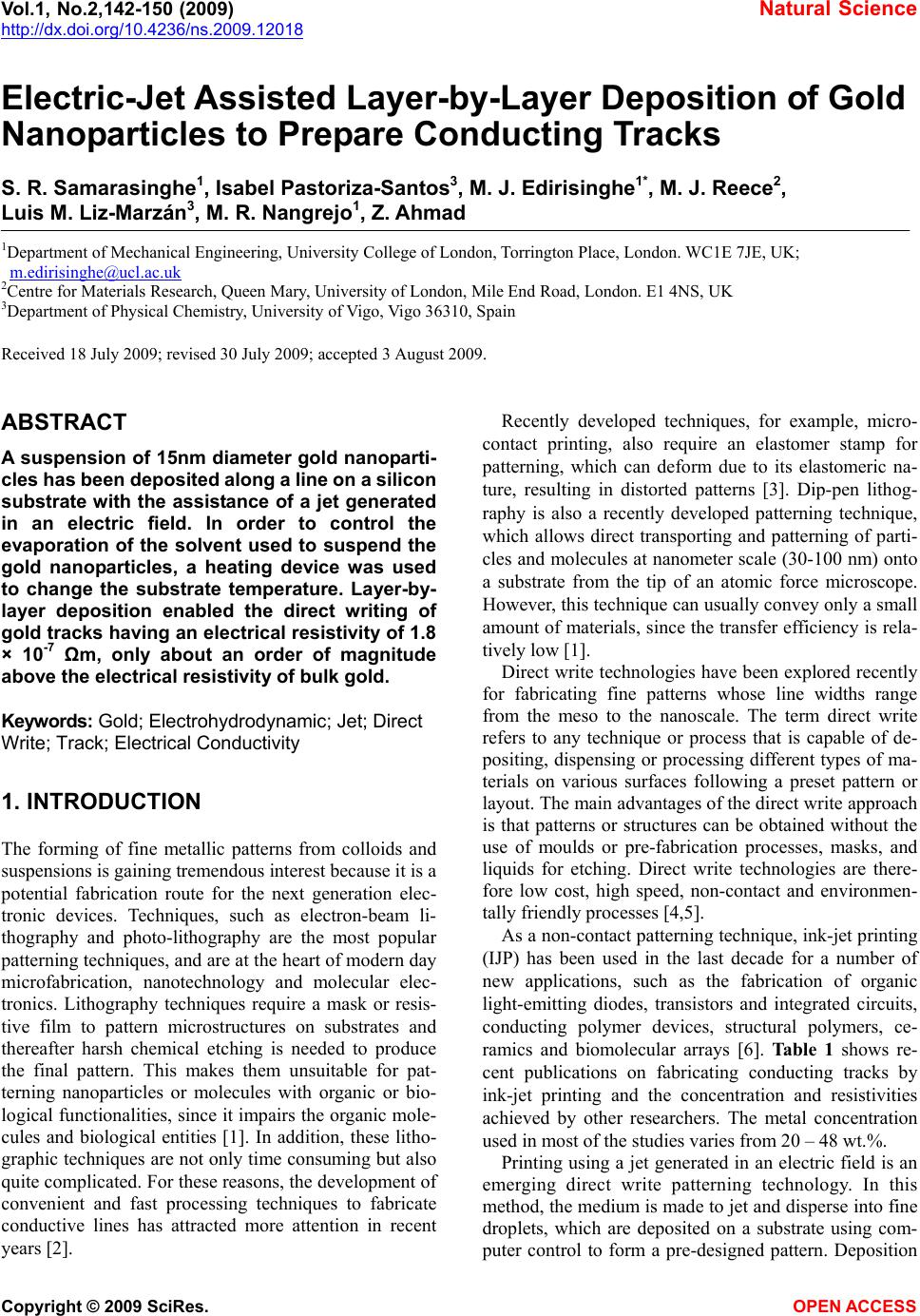
 Vol.1, No.2,142-150 (2009) Natural Science http://dx.doi.org/10.4236/ns.2009.12018 Copyright © 2009 SciRes. OPEN ACCESS Electric-Jet Assisted Layer-by-Layer Deposition of Gold Nanoparticles to Prepare Conducting Tracks S. R. Samarasinghe1, Isabel Pastoriza-Santos3, M. J. Edirisinghe1*, M. J. Reece2, Luis M. Liz-Marzán3, M. R. Nangrejo1, Z. Ahmad 1Department of Mechanical Engineering, University College of London, Torrington Place, London. WC1E 7JE, UK; m.edirisinghe@ucl.ac.uk 2Centre for Materials Research, Queen Mary, University of London, Mile End Road, London. E1 4NS, UK 3Department of Physical Chemistry, University of Vigo, Vigo 36310, Spain Received 18 July 2009; revised 30 July 2009; accepted 3 August 2009. ABSTRACT A suspension of 15nm diameter gold nanoparti- cles has been deposited along a line on a silicon substrate with the assistance of a jet generated in an electric field. In order to control the evaporation of the solvent used to suspend the gold nanoparticles, a heating device was used to change the substrate temperature. Layer-by- layer deposition enabled the direct writing of gold tracks having an electrical resistivity of 1.8 × 10⁻⁷ Ωm, only about an order of magnitude above the electrical resistivity of bulk gold. Keywords: Gold; Electrohydrodynamic; Jet; Direct Write; Track; Electrical Conductivity 1. INTRODUCTION The forming of fine metallic patterns from colloids and suspensions is gaining tremendous interest because it is a potential fabrication route for the next generation elec- tronic devices. Techniques, such as electron-beam li- thography and photo-lithography are the most popular patterning techniques, and are at the heart of modern day microfabrication, nanotechnology and molecular elec- tronics. Lithography techniques require a mask or resis- tive film to pattern microstructures on substrates and thereafter harsh chemical etching is needed to produce the final pattern. This makes them unsuitable for pat- terning nanoparticles or molecules with organic or bio- logical functionalities, since it impairs the organic mole- cules and biological entities [1]. In addition, these litho- graphic techniques are not only time consuming but also quite complicated. For these reasons, the development of convenient and fast processing techniques to fabricate conductive lines has attracted more attention in recent years [2]. Recently developed techniques, for example, micro- contact printing, also require an elastomer stamp for patterning, which can deform due to its elastomeric na- ture, resulting in distorted patterns [3]. Dip-pen lithog- raphy is also a recently developed patterning technique, which allows direct transporting and patterning of parti- cles and molecules at nanometer scale (30-100 nm) onto a substrate from the tip of an atomic force microscope. However, this technique can usually convey only a small amount of materials, since the transfer efficiency is rela- tively low [1]. Direct write technologies have been explored recently for fabricating fine patterns whose line widths range from the meso to the nanoscale. The term direct write refers to any technique or process that is capable of de- positing, dispensing or processing different types of ma- terials on various surfaces following a preset pattern or layout. The main advantages of the direct write approach is that patterns or structures can be obtained without the use of moulds or pre-fabrication processes, masks, and liquids for etching. Direct write technologies are there- fore low cost, high speed, non-contact and environmen- tally friendly processes [4,5]. As a non-contact patterning technique, ink-jet printing (IJP) has been used in the last decade for a number of new applications, such as the fabrication of organic light-emitting diodes, transistors and integrated circuits, conducting polymer devices, structural polymers, ce- ramics and biomolecular arrays [6]. Table 1 shows re- cent publications on fabricating conducting tracks by ink-jet printing and the concentration and resistivities achieved by other researchers. The metal concentration used in most of the studies varies from 20 – 48 wt.%. Printing using a jet generated in an electric field is an emerging direct write patterning technology. In this method, the medium is made to jet and disperse into fine droplets, which are deposited on a substrate using com- puter control to form a pre-designed pattern. Deposition  S. R. Samarasinghe et al. / Natural Science 1 (2009) 142-150 Copyright © 2009 SciRes. OPEN ACCESS 143 Table 1. Summary of recent works on fabricating conducting tracks by IJP. Metal Particle Size (nm) Width (µm) Conc. (wt.%) Curing Condition Resistivity (Ωm) Ref. Ag 10 – 20 60 34.5 Electrical 2.7 x 10⁻⁸ [10] Ag 21 90 20 150 0C 3.2 x 10⁻⁸ [11] Ag 1 – 10 125 30 300 0C 3.5 x 10⁻⁷ [12] Ag 20 65 20 300 0C 3.5 x 10⁻⁸ [13] Ag - 100 16 150 0C 4.8 x 10⁻⁸ [14] Ag - 750 48 300 0C 1.5 x 10⁻⁷ [15] Ag 10 – 50 130 25 260 0C 1.6 x 10⁻⁷ [2] Ag 5 – 10 160 60 Microwave 1.6 x 10⁻⁷ [16] Ag 5 – 7 1500 10 320 0C 1.1 x 10⁻⁶ [6] Au 2 – 4 17 30 Laser 1.4 x 10⁻⁷ [17] Au 2 – 5 20 30 Laser 1.4 x 10⁻⁷ [18] Au - 360 31 500 0C 2.7 x 10⁻⁷ [19] Au 2 – 4 125 34 Laser 6.2 x 10⁻⁸ [20] Cu 40 – 50 65 20 325 0C 1.72 x 10⁻⁷ [21] Figure 1. Schematic diagram of the electrohydrodynamic jet printing process. of materials using electric field assisted jet printing of- fers some advantages over other non-contact printing techniques. Firstly, by careful tailoring of the physical properties of the medium and by suitably fixing its flow rate and the applied voltage controlling the electric field it is possible to produce very fine droplets in the range of 40nm - 1.8µm [7,8]. Second, the diameter of the capil- laries (needles, nozzles) used in this method is much coarser (> 100µm inner diameter) than the capillaries used in ink-jet printing (usually around 20-60µm). The use of larger capillaries reduces the possibilities of blockages and allows viscous suspension containing high volume loading (above 30 vol.%) of solid particles to be processed [9]. Electric-field assisted jet printing has been used to produce conducting tracks from silver nanoparticles [22,23], the silver concentrations used in their experi- ments varied from 20 – 30 wt. %. In contrast, in this 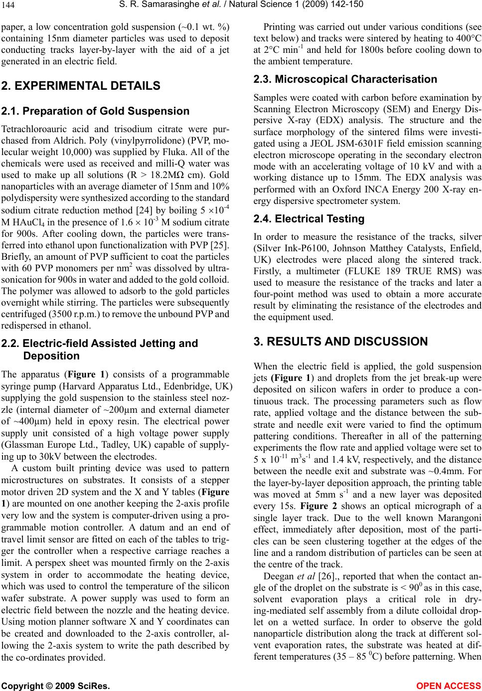 S. R. Samarasinghe et al. / Natural Science 1 (2009) 142-150 Copyright © 2009 SciRes. OPEN ACCESS 144 paper, a low concentration gold suspension (~0.1 wt. %) containing 15nm diameter particles was used to deposit conducting tracks layer-by-layer with the aid of a jet generated in an electric field. 2. EXPERIMENTAL DETAILS 2.1. Preparation of Gold Suspension Tetrachloroauric acid and trisodium citrate were pur- chased from Aldrich. Poly (vinylpyrrolidone) (PVP, mo- lecular weight 10,000) was supplied by Fluka. All of the chemicals were used as received and milli-Q water was used to make up all solutions (R > 18.2M cm). Gold nanoparticles with an average diameter of 15nm and 10% polydispersity were synthesized according to the standard sodium citrate reduction method [24] by boiling 5 10-4 M HAuCl4 in the presence of 1.6 10-3 M sodium citrate for 900s. After cooling down, the particles were trans- ferred into ethanol upon functionalization with PVP [25]. Briefly, an amount of PVP sufficient to coat the particles with 60 PVP monomers per nm2 was dissolved by ultra- sonication for 900s in water and added to the gold colloid. The polymer was allowed to adsorb to the gold particles overnight while stirring. The particles were subsequently centrifuged (3500 r.p.m.) to remove the unbound PVP and redispersed in ethanol. 2.2. Electric-field Assisted Jetting and Deposition The apparatus (Figure 1) consists of a programmable syringe pump (Harvard Apparatus Ltd., Edenbridge, UK) supplying the gold suspension to the stainless steel noz- zle (internal diameter of ~200µm and external diameter of ~400µm) held in epoxy resin. The electrical power supply unit consisted of a high voltage power supply (Glassman Europe Ltd., Tadley, UK) capable of supply- ing up to 30kV between the electrodes. A custom built printing device was used to pattern microstructures on substrates. It consists of a stepper motor driven 2D system and the X and Y tables (Figure 1) are mounted on one another keeping the 2-axis profile very low and the system is computer-driven using a pro- grammable motion controller. A datum and an end of travel limit sensor are fitted on each of the tables to trig- ger the controller when a respective carriage reaches a limit. A perspex sheet was mounted firmly on the 2-axis system in order to accommodate the heating device, which was used to control the temperature of the silicon wafer substrate. A power supply was used to form an electric field between the nozzle and the heating device. Using motion planner software X and Y coordinates can be created and downloaded to the 2-axis controller, al- lowing the 2-axis system to write the path described by the co-ordinates provided. Printing was carried out under various conditions (see text below) and tracks were sintered by heating to 400°C at 2°C min-1 and held for 1800s before cooling down to the ambient temperature. 2.3. Microscopical Characterisation Samples were coated with carbon before examination by Scanning Electron Microscopy (SEM) and Energy Dis- persive X-ray (EDX) analysis. The structure and the surface morphology of the sintered films were investi- gated using a JEOL JSM-6301F field emission scanning electron microscope operating in the secondary electron mode with an accelerating voltage of 10 kV and with a working distance up to 15mm. The EDX analysis was performed with an Oxford INCA Energy 200 X-ray en- ergy dispersive spectrometer system. 2.4. Electrical Testing In order to measure the resistance of the tracks, silver (Silver Ink-P6100, Johnson Matthey Catalysts, Enfield, UK) electrodes were placed along the sintered track. Firstly, a multimeter (FLUKE 189 TRUE RMS) was used to measure the resistance of the tracks and later a four-point method was used to obtain a more accurate result by eliminating the resistance of the electrodes and the equipment used. 3. RESULTS AND DISCUSSION When the electric field is applied, the gold suspension jets (Figure 1) and droplets from the jet break-up were deposited on silicon wafers in order to produce a con- tinuous track. The processing parameters such as flow rate, applied voltage and the distance between the sub- strate and needle exit were varied to find the optimum pattering conditions. Thereafter in all of the patterning experiments the flow rate and applied voltage were set to 5 x 10-11 m3s-1 and 1.4 kV, respectively, and the distance between the needle exit and substrate was ~0.4mm. For the layer-by-layer deposition approach, the printing table was moved at 5mm s-1 and a new layer was deposited every 15s. Figure 2 shows an optical micrograph of a single layer track. Due to the well known Marangoni effect, immediately after deposition, most of the parti- cles can be seen clustering together at the edges of the line and a random distribution of particles can be seen at the centre of the track. Deegan et al [26]., reported that when the contact an- gle of the droplet on the substrate is < 900 as in this case, solvent evaporation plays a critical role in dry- ing-mediated self assembly from a dilute colloidal drop- let on a wetted surface. In order to observe the gold nanoparticle distribution along the track at different sol- vent evaporation rates, the substrate was heated at dif- ferent temperatures (35 – 85 0C) before patterning. When 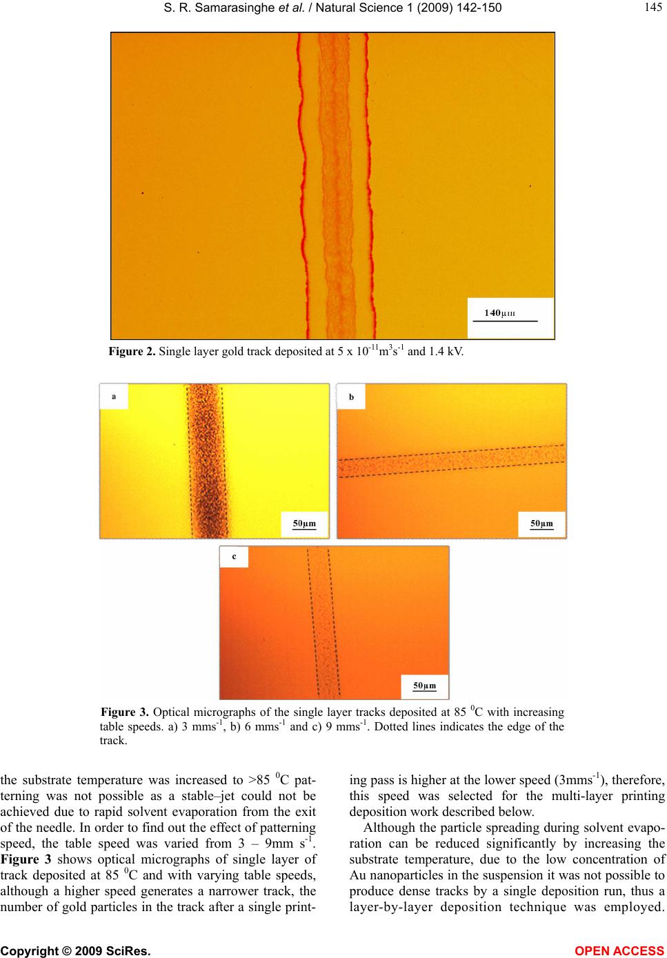 S. R. Samarasinghe et al. / Natural Science 1 (2009) 142-150 Copyright © 2009 SciRes. OPEN ACCESS 145 Figure 2. Single layer gold track deposited at 5 x 10-11m3s-1 and 1.4 kV. Figure 3. Optical micrographs of the single layer tracks deposited at 85 0C with increasing table speeds. a) 3 mms-1, b) 6 mms-1 and c) 9 mms-1. Dotted lines indicates the edge of the track. the substrate temperature was increased to >85 0C pat- terning was not possible as a stable–jet could not be achieved due to rapid solvent evaporation from the exit of the needle. In order to find out the effect of patterning speed, the table speed was varied from 3 – 9mm s-1. Figure 3 shows optical micrographs of single layer of track deposited at 85 0C and with varying table speeds, although a higher speed generates a narrower track, the number of gold particles in the track after a single print- ing pass is higher at the lower speed (3mms-1), therefore, this speed was selected for the multi-layer printing deposition work described below. Although the particle spreading during solvent evapo- ration can be reduced significantly by increasing the substrate temperature, due to the low concentration of Au nanoparticles in the suspension it was not possible to produce dense tracks by a single deposition run, thus a layer-by-layer deposition technique was employed. 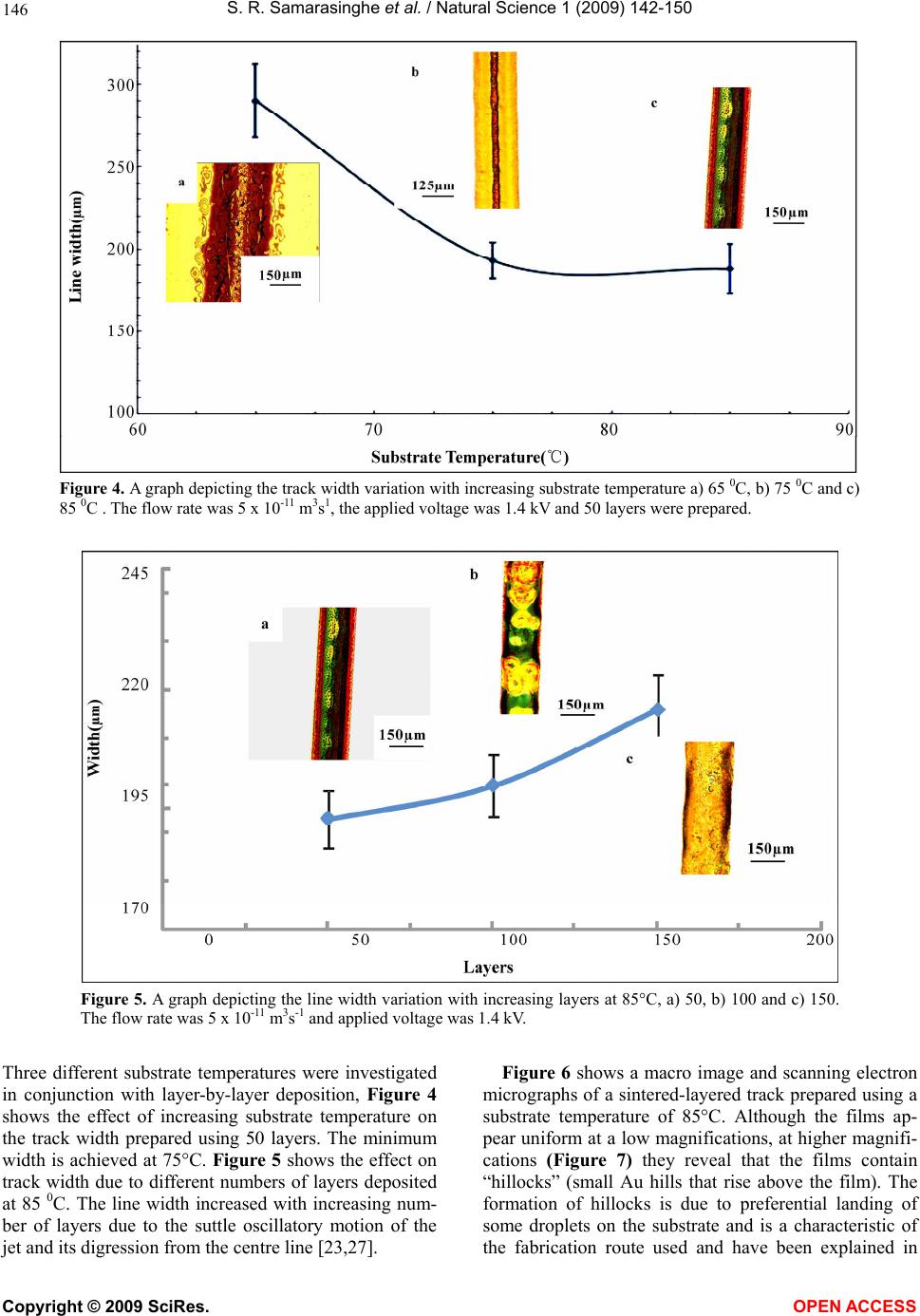 S. R. Samarasinghe et al. / Natural Science 1 (2009) 142-150 Copyright © 2009 SciRes. OPEN ACCESS 146 Figure 4. A graph depicting the track width variation with increasing substrate temperature a) 65 0C, b) 75 0C and c) 85 0C . The flow rate was 5 x 10-11 m3s1, the applied voltage was 1.4 kV and 50 layers were prepared. Figure 5. A graph depicting the line width variation with increasing layers at 85°C, a) 50, b) 100 and c) 150. The flow rate was 5 x 10-11 m3s-1 and applied voltage was 1.4 kV. Three different substrate temperatures were investigated in conjunction with layer-by-layer deposition, Figure 4 shows the effect of increasing substrate temperature on the track width prepared using 50 layers. The minimum width is achieved at 75°C. Figure 5 shows the effect on track width due to different numbers of layers deposited at 85 0C. The line width increased with increasing num- ber of layers due to the suttle oscillatory motion of the jet and its digression from the centre line [23,27]. Figure 6 shows a macro image and scanning electron micrographs of a sintered-layered track prepared using a substrate temperature of 85°C. Although the films ap- pear uniform at a low magnifications, at higher magnifi- cations (Figure 7) they reveal that the films contain “hillocks” (small Au hills that rise above the film). The formation of hillocks is due to preferential landing of some droplets on the substrate and is a characteristic of the fabrication route used and have been explained in 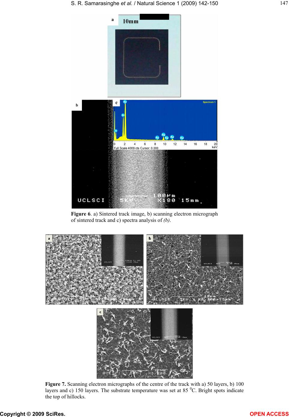 S. R. Samarasinghe et al. / Natural Science 1 (2009) 142-150 Copyright © 2009 SciRes. OPEN ACCESS 147 Figure 6. a) Sintered track image, b) scanning electron micrograph of sintered track and c) spectra analysis of (b). Figure 7. Scanning electron micrographs of the centre of the track with a) 50 layers, b) 100 layers and c) 150 layers. The substrate temperature was set at 85 0C. Bright spots indicate the top of hillocks. 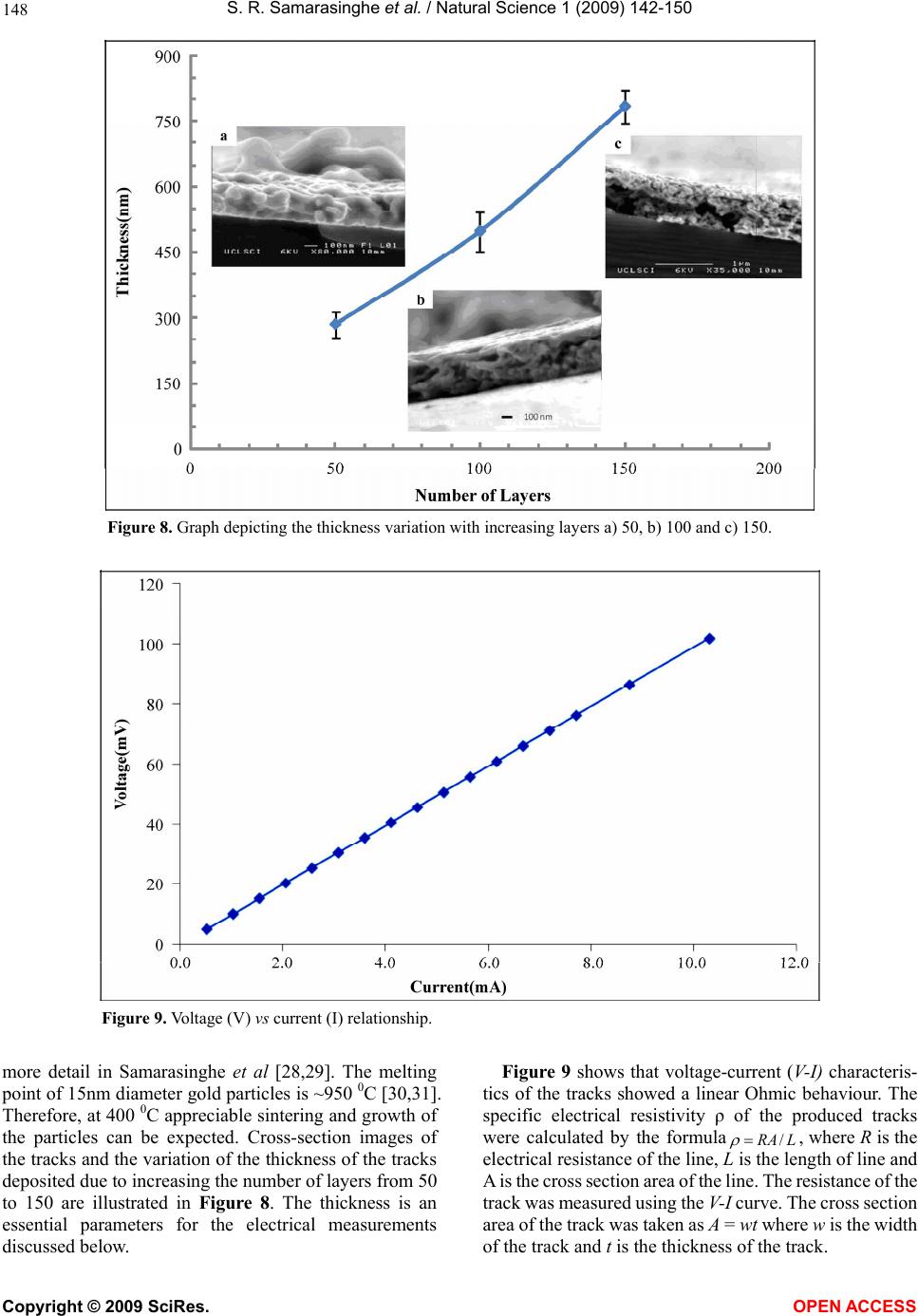 S. R. Samarasinghe et al. / Natural Science 1 (2009) 142-150 Copyright © 2009 SciRes. OPEN ACCESS 148 Figure 8. Graph depicting the thickness variation with increasing layers a) 50, b) 100 and c) 150. Figure 9. Voltage (V) vs current (I) relationship. more detail in Samarasinghe et al [28,29]. The melting point of 15nm diameter gold particles is ~950 0C [30,31]. Therefore, at 400 0C appreciable sintering and growth of the particles can be expected. Cross-section images of the tracks and the variation of the thickness of the tracks deposited due to increasing the number of layers from 50 to 150 are illustrated in Figure 8. The thickness is an essential parameters for the electrical measurements discussed below. Figure 9 shows that voltage-current (V-I) characteris- tics of the tracks showed a linear Ohmic behaviour. The specific electrical resistivity of the produced tracks were calculated by the formulaLRA/ , where R is the electrical resistance of the line, L is the length of line and A is the cross section area of the line. The resistance of the track was measured using the V-I curve. The cross section area of the track was taken as A = wt where w is the width of the track and t is the thickness of the track. 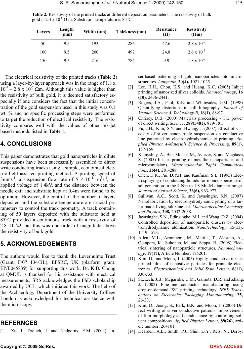 S. R. Samarasinghe et al. / Natural Science 1 (2009) 142-150 Copyright © 2009 SciRes. OPEN ACCESS 149 Table 2. Resistivity of the printed tracks at different deposition parameters. The resistivity of bulk gold is 2.4 x 10⁻⁸ m. Substrate temperature is 85°C. Layers Length (mm) Width (µm) Thickness (nm) Resistance (Ω) Resistivity (Ωm) 50 9.5 193 286 47.6 2.8 x 10⁻⁷ 100 9.5 200 497 24.8 2.6 x 10⁻⁷ 150 9.5 216 784 9.9 1.8 x 10⁻⁷ The electrical resistivity of the printed tracks (Table 2) using a layer-by-layer approach was in the range of 1.8 x 10⁻⁷ – 2.8 x 10⁻⁷ m. Although this value is higher than the resistivity of bulk gold, it is deemed satisfactory es- pecially if one considers the fact that the initial concen- tration of the gold suspension used in this study was 0.1 wt. % and no specific processing steps were performed to target the reduction of electrical resistivity. The resis- tivity compares well with the values of other ink-jet based methods listed in Table 1. 4. CONCLUSIONS This paper demonstrates that gold nanoparticles in dilute suspensions have been successfully assembled to direct write conducting tracks using a simple, economical elec- tric-field assisted printing method. A printing speed of 3mms-1, a suspension flow rate of 5 × 10-11 m 3s-1, an applied voltage of 1.4kV, and the distance between the needle exit and substrate kept at 0.4m were found to be optimum. However, the control of the number of layers deposited and the substrate temperature are crucial pa- rameters to control the track geometry. A track contain- ing of 50 layers deposited with the substrate held at 85°C provided a continuous track with a resistivity of 2.8×10⁻⁷, but this was one order of magnitude above the resistivity of bulk gold. 5. ACKNOWLEDGEMENTS The authors would like to thank the Leverhulme Trust (Grant: F/07 134/BL), EPSRC, UK (platform grant: EP/E045839) for supporting this work. Dr. K.B. Chong at QMUL is thanked for his assistance with electrical measurements; SRS acknowledges the PhD scholarship awarded by UCL, which initiated this work. The help of the Archaeology Department of the University College London is acknowledged for technical assistance with the microscopy. REFERNCES [1] Xu, J., Drelich, J. and Nadgorny, E.M. (2004) La- ser-based patterning of gold nanoparticles into micro- structures. Langmuir, 20(4), 1021-1025. [2] Lee, H.H., Chou, K.S. and Huang, K.C. (2005) Inkjet printing of nanosized silver colloids. Nanotechnology, 16 (10), 2436-2441. [3] Rogers, J.A., Paul, K.E. and Whitesides, G.M. (1998) Quantifying distortions in soft lithography. Journal of Vacuum Science & Technology B, 16(1), 88-97. [4] Chrisey, D.B. (2000) Materials processing - The power of direct writing. Science, 289(5481), 879-881. [5] Yu, J.H., Kim, S.Y. and Hwang, J. (2007) Effect of vis- cosity of silver nanoparticle suspension on conductive line patterned by electrohydrodynamic jet printing. Ap- plied Physics A-Materials Science & Processing, 89(1), 157-159. [6] Kamyshny, A., Ben-Moshe, M., Aviezer, S. and Magdassi, S. (2005) Ink-jet printing of metallic nanoparticles and microemulsions. Macromolecular Rapid Communica- tions, 26(4), 281-288. [7] Chen, D.R., Pui, D.Y.H. and Kaufman, S.L. (1995) Elec- trospraying of conducting liquids for monodisperse aero- sol generation in the 4 Nm to 1.8 Mu-M diameter range. Journal of Aerosol Science, 26(6), 963-977. [8] Sullivan, A.C., Scott, K. and Jayasinghe, S.N. (2007) Nanofabrication by electrohydrodynamic jetting of a tai- lor-made living siloxane sol. Macromolecular Chemistry and Physics, 208, 2032-2038. [9] Jayasinghe, S.N., Edirisinghe, M.J. and Wang, D.Z. (2004) Controlled deposition of nanoparticle clusters by elec- trohydrodynamic atomization. Nanotechnology, 15(11), 1519-1523. [10] Allen, M.L., Aronniemi, M., Mattila, T., Alastalo, A., Ojanpera, K., Suhonen, M. and Seppa, H. (2008) Elec- trical sintering of nanoparticle structures. Nanotechnol- ogy, 19(17), Article Number: 175201. [11] Kim, D., and Moon, J. (2005) Highly conductive ink jet printed films of nanosilver particles for printable elec- tronics. Electrochemical and Solid State Letters, 8(11), J30-J33. [12] Szczech, J.B., Megaridis, C.M., Gamota, D.R. and Zhang, J. (2002) Fine-line conductor manufacturing using drop-on-demand PZT printing technology. IEEE Trans- actions on Electronics Packaging Manufacturing, 25, 26-33. [13] Kim, D., Jeong, S., Park, B.K. and Moon, J. (2006) Di- rect writing of silver conductive patterns: Improvement of film morphology and conductance by controlling sol- vent compositions. Applied Physics Letters, 89(26), arti- cle number: 264101. [14] Dearden, A.L., Smith, P.J., Shin, D.Y., Reis, N., Derby, 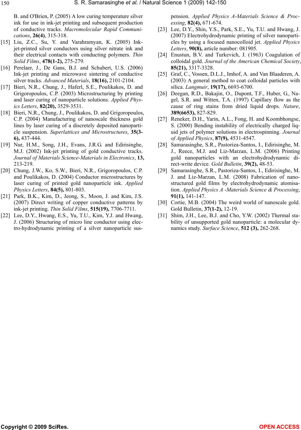 S. R. Samarasinghe et al. / Natural Science 1 (2009) 142-150 Copyright © 2009 SciRes. OPEN ACCESS 150 B. and O'Brien, P. (2005) A low curing temperature silver ink for use in ink-jet printing and subsequent production of conductive tracks. Macromolecular Rapid Communi- cations, 26(4), 315-318. [15] Liu, Z.C., Su, Y. and Varahramyan, K. (2005) Ink- jet-printed silver conductors using silver nitrate ink and their electrical contacts with conducting polymers. Thin Solid Films, 478(1-2), 275-279. [16] Perelaer, J., De Gans, B.J. and Schubert, U.S. (2006) Ink-jet printing and microwave sintering of conductive silver tracks. Advanced Materials, 18(16), 2101-2104. [17] Bieri, N.R., Chung, J., Haferl, S.E., Poulikakos, D. and Grigoropoulos, C.P. (2003) Microstructuring by printing and laser curing of nanoparticle solutions. Applied Phys- ics Letters, 82(20), 3529-3531. [18] Bieri, N.R., Chung, J., Poulikakos, D. and Grigoropoulos, C.P. (2004) Manufacturing of nanoscale thickness gold lines by laser curing of a discretely deposited nanoparti- cle suspension. Superlattices and Microstructures, 35(3- 6), 437-444. [19] Nur, H.M., Song, J.H., Evans, J.R.G. and Edirisinghe, M.J. (2002) Ink-jet printing of gold conductive tracks. Journal of Materials Science-Materials in Electronics, 13, 213-219. [20] Chung, J.W., Ko, S.W., Bieri, N.R., Grigoropoulos, C.P. and Poulikakos, D. (2004) Conductor microstructures by laser curing of printed gold nanoparticle ink. Applied Physics Letters, 84(5), 801-803. [21] Park, B.K., Kim, D., Jeong, S., Moon, J. and Kim, J.S. (2007) Direct writing of copper conductive patterns by ink-jet printing. Thin Solid Films, 515(19), 7706-7711. [22] Lee, D.Y., Hwang, E.S., Yu, T.U., Kim, Y.J. and Hwang, J. (2006) Structuring of micro line conductor using elec- tro-hydrodynamic printing of a silver nanoparticle sus- pension. Applied Physics A-Materials Science & Proc- essing, 82(4), 671-674. [23] Lee, D.Y., Shin, Y.S., Park, S.E., Yu, T.U. and Hwang, J. (2007) Electrohydrodynamic printing of silver nanoparti- cles by using a focused nanocolloid jet. Applied Physics Letters, 90(8), article number: 081905. [24] Enustun, B.V. and Turkevich, J. (1963) Coagulation of colloidal gold. Journal of the American Chemical Society, 85(21), 3317-3328. [25] Graf, C., Vossen, D.L.J., Imhof, A. and Van Blaaderen, A. (2003) A general method to coat colloidal particles with silica. Langmuir, 19(17), 6693-6700. [26] Deegan, R.D., Bakajin, O., Dupont, T.F., Huber, G., Na- gel, S.R. and Witten, T.A. (1997) Capillary flow as the cause of ring stains from dried liquid drops. Nature, 389(6653), 827-829. [27] Reneker, D.H., Yarin, A.L., Fong, H. and Koombhongse, S. (2000) Bending instability of electrically charged liq- uid jets of polymer solutions in electrospinning. Journal of Applied Physics, 87(9), 4531-4547. [28] Samarasinghe, S.R., Pastoriza-Santos, I., Edirisinghe, M. J., Reece, M.J. and Liz-Marzan, L.M. (2006) Printing gold nanoparticles with an electrohydrodynamic di- rect-write device. Gold Bulletin, 39(2), 48-53. [29] Samarasinghe, S.R., Pastoriza-Santos, I., Edirisinghe, M. J. and Liz-Marzan, L.M. (2008) Fabrication of nano- structured gold films by electrohydrodynamic atomisa- tion. Applied Physics A -Materials Science & Processing, 91(1), 141-147. [30] Cortie, M.B. (2004) The weird world of nanoscale gold. Gold Bulletin, 37(1-2), 12-19. [31] Shim, J.H., Lee, B.J. and Cho, Y.W. (2002) Thermal sta- bility of unsupported gold nanoparticle: a molecular dy- namics study. Surface Science, 512 (3), 262-268.
|