Journal of Electromagnetic Analysis and Applications
Vol. 2 No. 9 (2010) , Article ID: 2770 , 8 pages DOI:10.4236/jemaa.2010.29073
Scaling Relationships for Input Energy in Electromagnetic Welding of Similar and Dissimilar Metals
![]()
1Accelerator & Pulse Power Division, Bhabha Atomic Research Centre, Mumbai, India; 2ADS Target Development Section, Bhabha Atomic Research Centre, Mumbai, India; 3Mechanical Metallurgy Section, Bhabha Atomic Research Centre, Mumbai, India
Email: Satendra Kumar skdagur@yahoo.com
Received July 2nd, 2010; revised August 18th, 2010; accepted August 23rd, 2010
Keywords: Electromagnetic Welding, Collision Velocity, Capacitor Bank, Lorentz Force, Ringing Frequency, Energy Scaling Relationships
ABSTRACT
In Electromagnetic Welding (EMW) process, the capacitive energy is the source of input energy. The tool that is used for welding comprises of an electromagnetic coil. The job piece to be welded is placed in close proximity with the coil. The welding is achieved by impact, when the colliding job pieces are accelerated towards each other by the Lorentz force. The electromagnetic and mechanical properties/ parameters of the equipment, tool and the job govern the overall welding process. We have described a procedure to calculate the capacitive input energies for jobs of different sizes. Data is given for welding of strips of aluminium, copper and S.S. in similar and dissimilar combinations. Since the EMW technique is used in limited applications, this type of data is not available. We have validated our model with some data available in the literature. It is hoped that, this information will help the designer, to select and standardize the system and process parameters.
1. Introduction
Electromagnetic Welding (EMW) is the state of art technology in the field of joining of metals. It has numerous advantages (suitability for welding of dissimilar metals being the important one among others), which have been reported earlier [1,2]. However, this technique has some inherent limitations, the major being: 1) lower efficiency for large size jobs (exceeding half a meter) and 2) higher energy requirement for the welding of low electrical conductivity metals. Due to these limitations, the idea of using this technique on wide scale has not received significant attention of the industry. Nevertheless, this technique if applied judiciously, keeping in mind the above facts, can be utilized for some industrial applications. Elaborate analysis of the process and system parameters in Electromagnetic Forming (EMF) has been reported by many authors [3-8]. Copper to brass welding is reported by K.Feas et al. [9]. V.Shribman et al. have discussed about high strength aluminium welds [10]. Ben Artzy et al. have done in depth analysis of the nature of weld interface [11].
The EMF process consists of three stages namely 1) free forming, 2) forming against a die (groove formation) and 3) welding. The energy required for these operations goes on increasing successively. For the process of EMF and EMW, there are no major attempts made in standardization of tool (forming/welding coil), the equipment (energy storage capacitor bank) and the process parameters, which undoubtedly is a formidable task.
We have made a modest effort in this direction, in the field of EMW. The data for input energy for different job sizes helps the designer to select the system components. We have chosen flat strips of similar and dissimilar metals (planar geometry) for analysis, for mainly two reasons: 1) simplicity of coil fabrication and 2) consideration of the fact that comparatively less research work is reported for planar geometry job pieces. In the beginning, we did analysis of electromagnetic Lorentz force based on the parameters of the capacitor bank, the work coil and job piece material. This is being reported separately.
It is found that the collision velocity is the crucial parameter in EMW process. Its dependence on the electromagnetic parameters and the effect of collision velocity on the welding microstructure has been reportedly recently [12]. It is well known fact that, the aluminium is the easiest metal to form or weld electromagnetically. It can even improve the welding efficiency in case of other metals. In other words, aluminium is best suited as a ‘Driver’ in EMW process.
In this paper, we are discussing the relationships between capacitor input energy, ringing frequency and the sizes and the materials of the jobs to be welded (in similar and dissimilar combinations). The mathematical model developed by us is validated for the data on welding of S.S. tubes, which is summarized in the end. These relationships are useful to arrive at operating and design parameters of the capacitor bank and the coil, which could possibly eliminate the need of building hardware prototypes.
2. Description of the Analytical Approach
The design approach discussed in this paper is based on computational and experimental data. Samples of aluminium, copper and S.S. of different sizes were welded in similar and dissimilar combinations and the corresponding process parameters were calculated by the softwares. It was observed that whenever good welding was achieved, the computed collision velocity for the corresponding operating parameters was of the order of 400 m/sec. Since the sample strips to be welded move in opposite directions (in our experiment), before collision, the velocity of individual strip was 200 m/sec. For the data given in Table 2, the computation of collision velocities and experimental verification is done. The input energy values mentioned in Tables 3-7 are predicted values to achieve the collision velocity of 400 m/sec and hence the welding. The comparison of the measured value for the data from literature and data calculated by our model is given. On the basis of this comparison, the correctness of the predicted values can be justified.
The electrical circuit simulation of the experimental set up (shown in Figure 1) was done using MATLABSIMULINK. For our set up, the electrical parameters were measured as R=10 mΩ, L=400 nH and C=200 µF. For these values, the circuit was found to be under damped. For a specific value of charging voltage, the software calculated the damped sinusoidal current in the circuit. This was given as input to MAXWELL–SV software, which calculated the values of magnetic field and current induced in the job piece.
The magnetic field density B generated by the coil is given by
 H =Jc(1)
and B=µH(2)
where Jc is coil current density and H magnetic field intensity.
The electric field density, E and current density, Jw in the job piece are given by
 E= -∂B/∂t(3)
and Jw= σE (4)
Lorentz force on the job piece is given by F= Jwx B (5)
The force generated (given by the above equation 5 is unidirectional and is of double the frequency of the input voltage/current frequency. The impulse generated is then given by Impulse =2 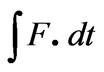 (6)
(6)
This impulse is used in plastic deformation and in setting up the collision velocity. A portion of energy is also lost in joule heating and in sonic and light energy during switching in the spark gap. Neglecting the losses during switching, one can write the energy conservation equation as
 CV2=
CV2=  LI2=V σ.
 + I2Rt +
  mvmax2(7)
where term (V σ. ) represents the plastic strain energy and ‘σ’ is plastic stress and ‘e’ is the plastic strain, ‘m’ is the mass of colliding strip and ‘v max’ is the collision velocity.
In EMF process, kinetic energy is fully utilized in forming (free deformation) and in welding process, it is partly used. The remaining kinetic energy is responsible to generate the collision velocity required for impact welding.
The force impulse (calculated by MAXWELL-SV) along with the geometry and mechanical properties were given as input to ANSYS software, which calculated the collision velocity. The properties of the materials used in the calculations are shown in Table1.
3. Description of the Experimental Work
The experimental layout of the EMW equipment is shown in Figure 1. It consists of high voltage power supply, energy storage capacitor bank, spark gap switch and the arrangement of the coil and the job piece. The dis-
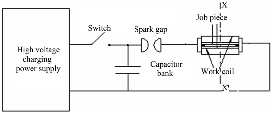
Figure 1. Schematic of EMW equipment.
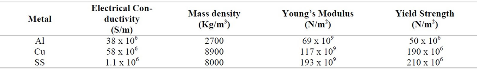
Table 1. Electrical and mechanical properties of the materials.
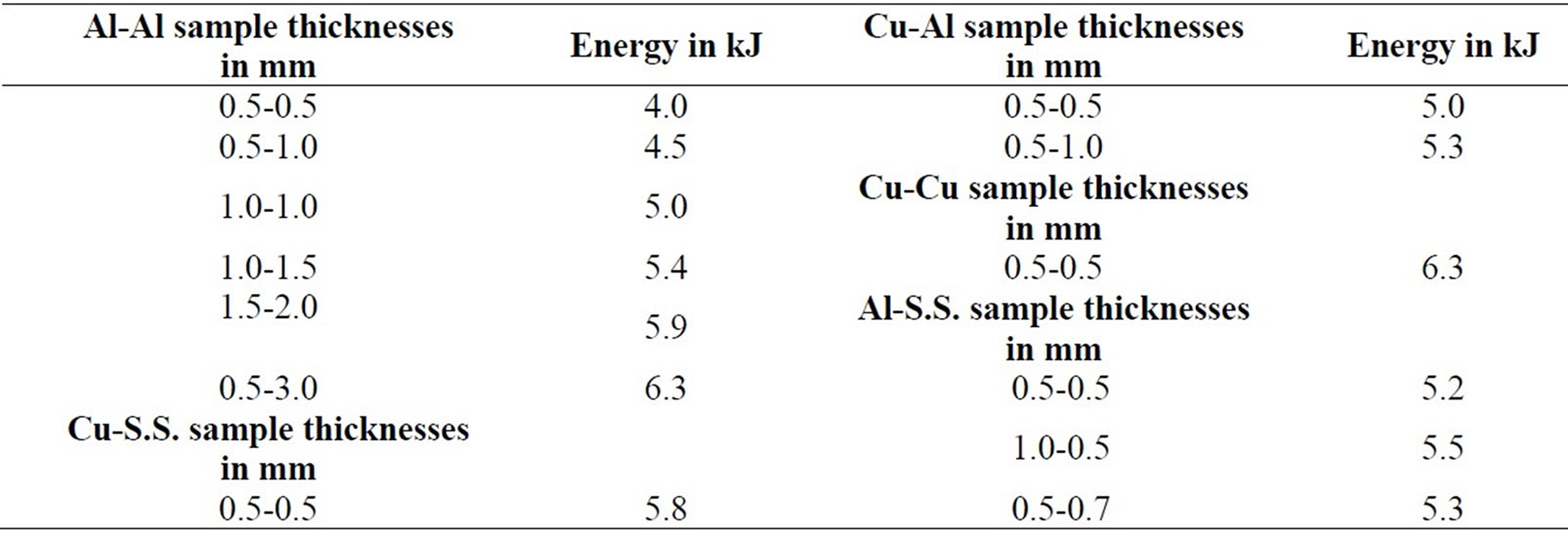
Table 2. Details of attempted weld samples in our laboratory.
Table 3. Showing energy requirement for welding Al-Al strips of different dimensions.
Table 4. Shows the energies required to weld Cu-Cu strips of different lengths and thicknesses.
Table 5. Shows energies required to weld Al-Cu strips of different thicknesses and lengths.
Table 6. Shows energies required to weld Al-S.S. strips of different thicknesses and lengths.
Table 7. Shows energies required to weld Cu-S.S. strips of different thicknesses and lengths.
charge of the capacitor bank creates a damped sinusoidal current in the coil, which induces anti phase currents in the job piece. The interaction of these currents results in the creation of Lorentz force, the latter being responsible for the deformation and impact welding. The isometric view of the arrangement of the welding set up is shown in Figure 2. We have adopted the H type coil discussed by T. Aizawa et al. [13].
It may be noted that the ‘driver’ is one of the important components in the assembly. The driver is high conductivity material which is used for the welding of low electrical conductivity metals. We have done extensive experimental and computational work on the performance of the drivers, which is being published separately [14]. A detailed procedure is given for the selection of the dimensions of the drivers and it’s frequency dependence. It is found that aluminium is the best driver material to achieve welding in all other metals.
Figure 2 shows the arrangement for coil, driver, job piece and end connectors. The base width of the coil is ‘wc’ which tapers down to ‘w’ near the job piece. The end connectors are placed at the ends along longitudinal direction, serve the purpose of providing the separation between the job pieces. They also enhance the induced currents in the job piece. The separation distance, is varied by using the end connectors of different thicknesses. The length of the job piece and the driver was 7cm, for the readings shown in Table 2. The job pieces collide with each other and a lap weld joint is obtained by impact.
Due to the limitation of the capacitor input energy and the life of the coil, we have limited our experimental trials for aluminium samples up to 3 mm thickness and that for copper and SS samples up to1mm thickness. The weld length and width in all the cases were 7 cms and 5 mm respectively. These details are given in Table 2. It was observed that for a good weld the computed collision velocity was found to be about 400 m/sec, in all these cases. The predicted (extrapolated) energy values for jobs of larger size, in Tables 3-7 are calculated so as to achieve this velocity. The input energy is worked out by using the soft wares mentioned above. Since there is complete agreement between the computational and experimental observations, it can be conclusively said that the rest of the computational results can predict scaled up energies for jobs of different materials and of larger size. The comparison of the calculated results with the data in the literature is also given in the end.
4. Discussion of the Results
It can be observed from Tables 3-7, that the input energy goes on increasing with size of the job piece. The energy is the least for welding of aluminium and it successively increases for copper and SS for welding of dissimilar combinations of these metals, the energy requirement is intermediate. When the input energy is applied, the EM force (Lorentz force) is generated in accordance with electrical conductivity of the job piece. Out of the total input energy, some part is spent in spark gap switch (in the form of light and sound). The remaining energy is distributed in the leads and the welding/forming coil. Hence for better efficiency, the lead lengths should be minimized. Out of the energy, coupled to the coil, a part is coupled to job piece, depending on magnetic coupling between the former and the latter. The energy coupled to the job piece is initially spent in deformation of the job piece. Successively higher energy is spent for deformation for aluminium, copper and SS. The kinetic energy
Figure 2. Shows the arrangement for coil, driver, job piece and end connector.
available for impact welding goes on diminishing in the same sequence. The collision velocity further reduces due to increase in mass density. In order to have good weld joint, the job pieces should have sufficient velocity at the time of collision. Thus the mechanical and electrical properties play crucial role in deciding the collision velocity.
As mentioned earlier, it was explicitly established (from experiments and the computations) that the collision velocity required to achieve weld was of the order of 400 m/sec and is independent of job sizes and the job material. The energies required for other sizes are calculated to achieve this velocity. Thus it is possible to establish scaling relationships with the help of mathematical model.
In EMW/EMF applications, it is desirable to operate at as high frequency as possible. The upper limit is set by the size of overall circuit. Figure 3 shows the variation of EM force for different frequencies and job piece conductivity values.
Table 3 shows the values of energy for the welding of aluminium strips of different thicknesses and lengths. The separation distance between the colliding strips was adjusted to 2 mm. The same separation was maintained for the readings in Table 4 to 7. The frequency values are calculated for capacitor bank with capacitances of 200 µF, 300 µF and 400 µF, operating at10 kV. In this table, decrease in frequency is observed due to increase of capacitance value. It can also be observed that the energy requirement goes on decreasing with the increase in frequency. This is because of the fact that at higher frequency more magnetic field is contained in the job piece and less magnetic field diffuses out, which results in making the process more efficient. This trend can be observed in all the readings in Tables 3-7. The energy requirement increases with length and thickness of the job piece. This due two reasons, viz.-1) There is increase of
Figure 3. Variation of EM force with frequency for various conductivity values of the job piece.
inductance of the overall circuit and 2) With the increase of thickness, more energy is spent in deformation, resulting in reduction of collision velocity.
It is desirable to use a capacitor bank of lower capacitance and higher voltage for jobs of larger size and of low conductivity materials. This type of selection can meet the demand of higher energy and higher ringing frequency simultaneously. For welding of the jobs with dimensions larger than that indicated in the tables, the ringing frequencies of the order of 30-40 kHz could be implemented.
Table 4 shows the values of energy required to weld copper strips of different dimensions, without using aluminium driver. When Table 3 and 4 are compared, it can be observed that, for the same size, copper needs higher energy as compared to aluminium, to get welded. This is owing to better mechanical strength and mass density of the former.
Table 5 shows the energy values to achieve welding of aluminium and copper strips of different sizes. For the results shown in Tables 5, 6 and 7 aluminium drivers of 70 mm length, 5 mm width and 0.5 mm thickness was used to drive the copper and S.S. strips. When the readings in Table 4 and 5 are compared, it can be observed that Al-Cu combination requires less energy as compared to Cu-Cu combination (compare reading 2 from Table 4 and reading 2 from Table 5).This is quite obvious, owing to the fact that Cu is mechanically stronger than Al.
Table 6 shows the energy values to achieve welding in aluminium and S.S. strips of different sizes. It can be observed from Table 5 and 6 that welding of Al-S.S. needs higher energy than Al-Cu, owing to better mechanical strength and mass density of S.S. as compared to that of copper.
From Table 6 and 7, one can observe that the energy required for welding of Cu-S.S. is higher than the corresponding combination of Al-S.S. This is again due to better mechanical properties of S.S. than that of copper.
The readings from Tables 3-7 can be broadly summarized as follows
1) The energy requirement increases with the increase in the dimensions of the job piece.
2) The energy requirement increases at lower frequencies due to increase of diffused out magnetic field, resulting in reduction in energy available for generating the velocity.
3) Aluminium needs the least energy for welding.
4) It is found that welding can be achieved at lesser energy for other similar and dissimilar welding combinations. Hence the use of aluminium as a driver is recommended.
5) The energy requirement goes on increasing successively for the combinations Al-Al, Al-Cu, Al-S.S., Cu-Cu and Cu-S.S. This could be explained on the basis of mass density and electrical and mechanical properties of the metals involved in the process.
6) It is interesting to note that in even case of copper the welding can be achieved at less energy. This explained elaborately in [14].
The Figures 4-9 show the photographs of samples welded in our laboratory.
Figure 4. Al-Al welded sample.

Figure 5. Al-Cu welded sample.
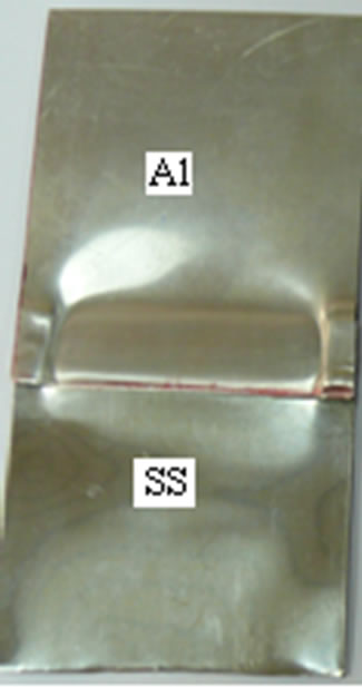
Figure 6.Al-S.S. welded sample.
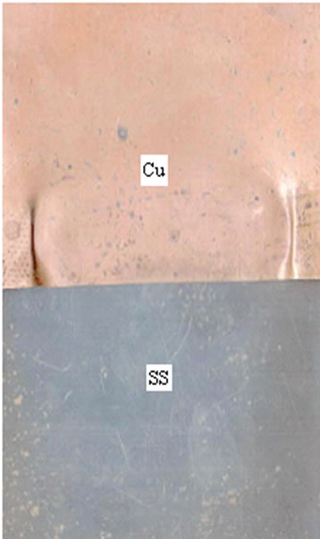
Figure 7. Cu-S.S. welded sample.

Figure 8. S.S.-S.S. welded sample.
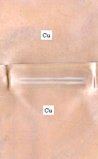
Figure 9. Cu-Cu welded sample.
5. Comparison of the Computed Results with EMW System for Fabrication of S.S. Fuel Pins
We have done the validation of our computational model with the data available for the welding set up reported by
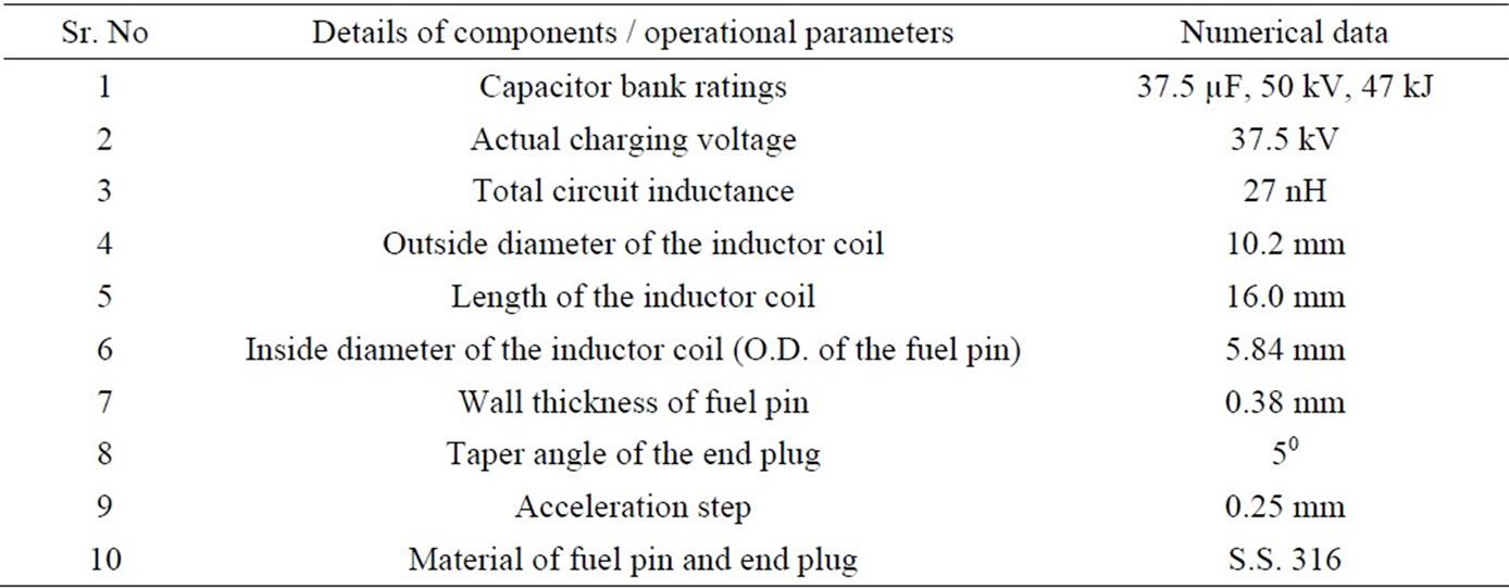
Table 8. Data used in computational model.

Table 9. Comparison of the data.
W.F.Brown et al. [15] which describes the electromagnetic welding of SS fuel pins used in the breeder reactor. They have used 47 kJ, 50 kV capacitor bank to achieve the welding of SS fuel pins with the end enclosure, using a single turn inductor. The weld results are qualified by mechanical and metallurgical tests. The data shown in Table 8 is taken as input data in our computational model.
Table 9 shows the comparison of the values reported in [10] and the values computed by our model. It can be observed that there is good amount of agreement.
It is interesting to note that the value of measured collision velocity (305 m/sec) reported in [10] is closely matching with the value calculated by our model (330 m/sec). This observation underlines the correctness of our computational model.
6. Conclusions
It is possible to establish scaling relationships for the input energies for welding of jobs of different sizes and the materials, in the case of EMW process. It is also possible to decide appropriate values of the capacitance and voltage for the capacitor bank, depending on the size of the job. The correctness of the computational model is validated, using the data available on welding of S.S. tubes. This analysis gives important inputs for the predictive design and the standardization procedures and is equally applicable for tubular jobs.
7. Acknowledgements
We thankfully acknowledge the help rendered by our colleague M. R. Kulkarni, during the experiments. Sincere thanks are also due to Dr. L. M. Gantayet, Director, BTD Group for encouragement and support for this activity.
REFERENCES
- S. Kumar, S. V. Desai, M. R. Kulkarni and D. P. Chakravarthy, “Development of Electro-Magnetic Welding Technique for Similar and Dissimilar Metal Strips,” National Welding Seminar-2008, Mumbai.
- S. Kumar, S. V. Desai, M. R. Kulkarni and D. P. Chakravarthy, “Electro-Magnetic Welding of Copper to Stainless Steel,” National Welding Seminar-2009, Kolkata.
- S. T. S. Al Hassani, J. L. Duncan and W. Johnson, “On the Parameters of the Magnetic Forming Process,” Journal of Mechanical Engineering Science, Vol. 16, No. 1, pp.1-9.
- S. T. S. Al Hassani, J. L. Duncan and W. Johnson, “The Influence of the Electrical and Geometrical Parameters in Magnetic Forming,” Proceedings of the 8th International MTDR conference, Manchester, UK, September 1967.
- K. Baines, J. L. Duncan and W. Johnson, “Electromagnetic Metal Forming,” Proceedings of the Institution of Mechanical Engineers, 180 (Pt. 1) 1965-6 4, 93.
- S. T. S. Al Hassani, J. L. Duncan and W. Johnson, “Analysis of the Electromagnetic Forming Process,” Proceedings of Cooperative Institutional Research Program, ASTME conference U.S.A., September 1967.
- G. K. Lal and M. J. Hillier, “The Electrodynamics of Electromagnetic Forming,” International Journal of Mechanical Science, Vol. 10, No. 6, 1968, pp. 491-500.
- G. K. Lal, “Electromagnetic Metal Forming,” IEEE Transactions on Industrial Applications, 1972, pp. 425- 429.
- K. Feas, T. Baaten, W. D. Waele and N. Debroux, “Joining of Copper to Brass Using Magnetic Pulse Welding,” 4th International Conference on High Speed Forming, 2010, pp. 84-96.
- V. Shribman, A. Stern, V. Livshitz and O. Gafri, “Magnetic Pulse Welding Produces High Strength Aluminium Welds,” Welding Journal, Vol. 81, 2002, pp 33-37.
- B. Artzy, A. Stern, N. Frage and V. Shribman, “Interface Phenomena in Aluminium-Magnesium Magnetic Pulse Welding,” Science and Technology of Welding and Joining, Vol. 13, No. 4, 2008, pp. 402-408.
- S. V. Desai, S. Kumar, P. Satyamurthy, J. K. Chakravartty and D. P. Chakravarthy, “Analysis of the Effect of Collision Velocity in Electromagnetic Welding Process of Aliminum Strips,” accepted for publication in International Journal of Electromagnetics and Mechanics in May 2010.
- T. Aizawa, K. Okagawa, M. Yoshizawa and N. Henmi, “Impulse Magnetic Pressure Seam Welding of Aluminium Sheets,” Impact Engineering and Applications, 2001, pp. 827-832.
- S. V. Desai, S. Kumar, P. Satyamurthy, J. K. Chakravartty and D. P. Chakravarthy, “Improvement of Performance of Electromagnetic Welding Process by Use of Driver Materials,” accepted for publication in International Journal of Electromagnetics and Mechanics in 2010.
- W. F. Brown, J. Bandas and N. T. Olsan, “Pulsed Magnetic Welding of Fast Breeder Reactor Fuel Pin End Closures,” Welding Journal, Vol. 57, No. 6, 1978, pp. 22-26.