Int'l J. of Communications, Network and System Sciences
Vol. 5 No. 6 (2012) , Article ID: 19660 , 15 pages DOI:10.4236/ijcns.2012.56046
Detection and Fortification Analysis of WiMAX Network: With Misbehavior Node Attack
Department of Electronics Engineering, Sardar Vallabhbhai National Institute of Technology, Surat, India
Email: {jharakesh.45, wankhedeva}@gmail.com, idris_bholebawa@yahoo.co.in, upena_dalal@yahoo.com
Received September 4, 2011; revised November 21, 2011; accepted April 16, 2012
Keywords: WiMAX, PHY Layer; MAC Layer; Network Layer WiMAX Architecture; QoS (Quality of Service); Misbehavior Node; OPNET Modeler
ABSTRACT
Wireless networks are playing an imperative role in our daily existence; in current scenario, the users want wireless connectivity for all location with all types of service. One of the major challenges for wireless network is security issue. First and foremost task is to detect the security attacks in the network and the second task is to prevent from an authorized attacks. In our view, a lot of researches are going on and somehow we have succeeded in the first case but the second task is very tough due to wireless channel. Our research is based on how to avoid network attack i.e. misbehavior node attack in the WiMAX system. In this paper we have proposed an algorithm for WiMAX network and our algorithm are able to prevent fixed as well as mobile misbehavior node attacks. As we know, misbehavior node misbehaves in the sense that the node does not esteem its MAC protocols and avariciously sends its packets without any restriction (Flooding of packets) because it doesn’t follow any protocol. Our proposed work based on the standard time required for communication for valid user with some threshold time for valid delay and some unwanted delay with network conditions. Our approach can control continuous flooding of packets and continuously transmits Constant Bit Rate (CBR) packets by misbehavior node, which introduces noise in the network and upset the performance of the network. In the mean while the valid user communicate in a trouble-free approach.
1. Introduction
The purpose of misbehavior node is not to function properly in the network. Misbehavior nodes achieve its goal by acting maliciously. It stops forwarding packet to other nodes, by simply start dropping the packets; consume the bandwidth of the network by broadcasting route when it is not necessary. The misbehavior nodes stop performing the basic task, and as a result, the network becomes congested and the traffic on the network leads to delay of data and degrade the performances of the network. The misbehaving node does not follow any protocol or any standard packet format, it simply generates Constant Bit Rate (CBR) traffic and increases packet dropping probability on the clients. The analysis on WiMAX network is done with the help of OPNET Modeler 14.5 [1].
The Node Model of WiMAX Subscriber Station (SS) and Misbehavior node is shown in Figures 1 and 2 respectively. We can observe that in misbehaving node the MAC (Media Access Control) Layer is absent, thus this node does not have to follow any MAC protocols or any MAC frame format, and it simply generates Constant Bit Rate (CBR) traffic from the application layer and degrade the performance of the entire network [2,3].
The main aim of this paper is to introduce the WiMAX network along with Misbehaving Node and to discuss the impact of this Misbehaving Node on the performance of whole network along with the brief explanation of its Physical Layer and MAC (Media Access Control) Layer. In second phase of this paper we have proposed one algorithm for detection and to overcome the problem of misbehavior node attack. The WiMAX network is implemented with the help of OPNET Modeler Networking tool [4].
This paper is organized as follows:
Section 2. In this section conferred about the Quality of Service (QoS) which is standardized by IEEE 802.16 WiMAX Forum, these QoS are the scheduling services which are set according to its priority on the Base Station (BS) to serve the Subscriber Stations (SS) in its range.
Section 3. Here we have illustrated the WiMAX Network Model implementation, this model is implemented with the help of OPNET Modeler 14.5v.
Section 4. In this section shown the parameters set on the Base Station (BS) and Subscriber Station (SS) according
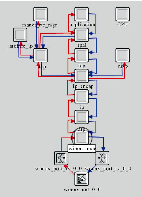
Figure 1. Node model of WiMAX subscriber station (SS).
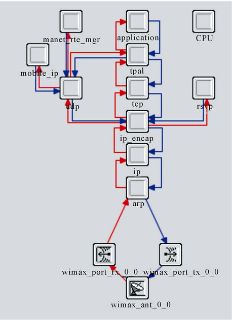
Figure 2. Node model of misbehaving node.
to IEEE 802.16 standards.
Section 5. This section is important here we have plotted tabular result to investigate the results for the performance of the network model on account of Misbehaving Node Attack with the help of graphs.
Section 6. Analyzed the Conclusion drawn from the results and Section 7. On this basis of research we have found that a lot work will require in future details are given Future Scopes section.
2. Quality of Service (QoS) in IEEE 802.16
Scheduling services are globally the data handling mechanisms allowing a fair distribution of resources between different WiMAX/802.16 users. Each connection is associated with a single data service and each data service is associated with a set of QoS parameters that quantify aspects of its behavior, known as a QoS class [5].
Four classes of QoS were defined in the IEEE 802.16d- 2004 standards (and then in WiMAX):
· Unsolicited Grant Service (UGS);
· Real-time Polling Service (rtPS);
· Non-real-time Polling Service (nrtPS);
· Best Effort (BE).
A fifth one has been added with IEEE 802.16e-2005:
· Extended real-time Polling Service (ertPS) class.
The purpose of scheduling is to allow every user, if possible, to have the suitable QoS required for his or her application. For example, a user sending an email does not require a real-time data stream, unlike another user having a Voice over IP (VoIP) application [6].
To support a wide variety of applications, WiMAX defines five scheduling services (Table 1) that should be supported by the base station MAC scheduler for data transport over a connection:
1) Unsolicited Grant Services (UGS): This is designed to support fixed-size data packets at a Constant Bit Rate (CBR). Examples of applications that may use this service are T1/E1 emulation and VoIP without silence suppression. The mandatory service flow parameters that define this service are maximum sustained traffic rate, maximum latency, tolerated jitter, and request/transmission policy.
2) Real-time Polling Services (rtPS): This service is designed to support real-time service flows, such as MPEG video, that generate variable-size data packets on a periodic basis. The mandatory service flow parameters that define this service are minimum reserved traffic rate, maximum sustained traffic rate, maximum latency, and request/transmission policy.
3) Non-real-time Polling Service (nrtPS): This service is designed to support delay-tolerant data streams, such as an FTP, that require variable-size data grants at a minimum guaranteed rate. The mandatory service flow parameters to define this service are minimum reserved traffic rate, maximum sustained traffic rate, traffic priority, and request/transmission policy.
4) Best-Effort (BE) Service: This service is designed to support data streams, such as Web browsing, that do not require a minimum service-level guarantee. The mandatory service flow parameters to define this service are maximum sustained traffic rate, traffic priority, and request/transmission policy.
5) Extended real-time Polling Service (ertPS) Service: This service is designed to support real-time applications, such as VoIP with silence suppression, that have variable data rates but require guaranteed data rate and delay. This service is defined only in IEEE 802.16e-2005, not in IEEE 802.16-2004.
3. WiMAX Network Model
This section describes the implementation of WiMAX network using OPNET Modeler 14.5 and the Performance Analysis of the network model is done on account of Misbehaving Node Attack. The network model design contains two network scenarios; the first scenario describes the implementation of WiMAX network, and the second scenario describes the performance of WiMAX network after applying misbehavior node. This network model is shown in Figure 3 where the whole WiMAX network is implemented on the map of INDIA as shown.
As shown in figure the network model contain three application servers to provide service to the clients. These servers are; VoIP server with an application of IP Telephony (PCM Quality) is placed at Delhi (INDIA), the Video Server with an application of Video Conferencing (Light) is placed at Kolkata (INDIA) and an FTP Server with an application of File Transfer (Light) is placed at Hyderabad (INDIA). Also two subnets are present in the network, these subnets are; Router Subnet and WiMAX Subnet. The router subnet provides route to the packets coming from servers to reach the clients. The WiMAX subnet provides the complete distribution of WiMAX clients in a cell based structure.
The Router subnet is placed at Nagpur (INDIA) which is shown in Figure 4.
This subnet contains the ASN-GW (Access Service
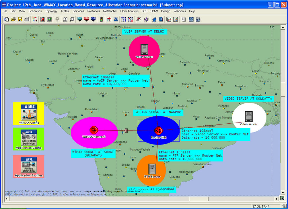
Figure 3. WiMAX network model.
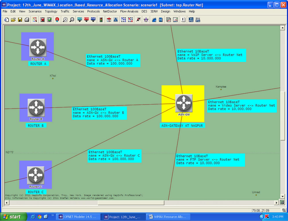
Figure 4. Router subnet of WiMAX network.
Network-Gateway) and the Ethernet routers. The ASNGW provides the connection between the Application Servers and the WiMAX network. The servers which are used in the network are Ethernet Servers using Ethernet links. The packets generated from the servers are first passes through ASN-GW and then it gets route to reach the WiMAX network. The link used to connect Servers and ASN-GW is Ethernet 10BaseT link. From the ASNGW the packets transmitted to the routers; Router A, Router B, and Router C through Ethernet 100 BaseT link in order to improve performance of the whole network.
Another subnet is WiMAX subnet which is shown in Figure 5.
This subnet is placed at Surat District (Gujarat-INDIA); in this subnet there are three WiMAX cells. According to IEEE 802.16 standards the cell radius of one Base Station (BS) is 50 kms theoretically and 30 kms practically, in our case we kept the cell radius to 15 kms so that the distance from one BS to another BS is 30 kms.
Cell 1 with Base Station 1 (BS1) is placed near Surat (Gujarat-INDIA); this cell is shown in Figure 6.
In this cell there are twelve WiMAX Subscriber Stations (SS), these SS are distributed randomly throughout the cell. The Subscriber Stations (SS) which are closer to Base Station (BS) is called Aggressive node and the modulation scheme is set to 64 QAM with 3/4 coding rate. The Subscriber Stations (SS) which are far from the Base Station (BS) is called Conservative node and the modulation scheme is set to 16 QAM with 1/2 coding rate. The Subscriber Stations (SS) which are very far from Base Station (BS) i.e. near the edges of the cell has the modulation scheme of QPSK with 1/2 coding rate [7,8].
Cell 2 with Base Station 2 (BS2) is placed near Bardoli (GUJ.); this cell is shown in Figure 7. In this cell there are 6 WiMAX clients, these clients are distributed randomly throughout the cell having the same modulation schemes as discussed above.
Cell 3 with Base Station 3 (BS3) is placed near Navsari (GUJ.); this cell is shown in Figure 8. In this cell there are nine WiMAX clients which are distributed randomly throughout the cell with same modulation as
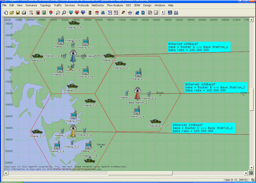
Figure 5. WiMAX subnet of WiMAX network.
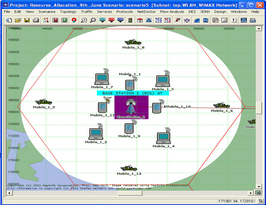
Figure 6. Cell 1 with BS1 in WiMAX subnet.
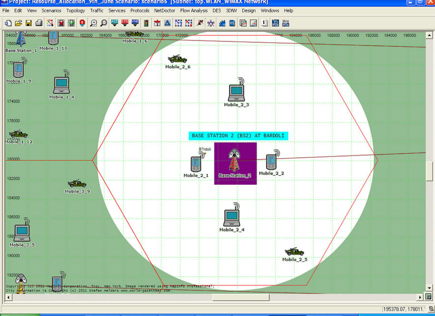
Figure 7. Cell 2 with BS2 in WiMAX subnet.
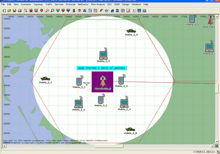
Figure 8. Cell 3 with BS3 in WiMAX subnet.
discussed above.
Base Station 1 (BS1) is in contact with Router A in Router Subnet through 100BaseT Ethernet link, similarly Base Station 2 (BS2) and Base Station 3 (BS3) are in contact with Router B and Router C in Router Subnet respectively.
In second Scenario the WiMAX Network Model is completely same, but only the difference is, there is one Misbehaving Node in each cell in WiMAX Subnet. This Subnet with Misbehaving Node is shown in Figure 9.
The Misbehaving Nodes in each cell are highlighted in the figure. These Nodes are Mobile_1_1 node in Cell 1, Mobile_2_1 node in Cell 2 and Mobile_3_1 node in Cell 3.
4. Network Simulation Parameters
Parameters associated with WiMAX Configuration Node are shown in Figure 10 and Table 1.
Here three MAC layer Scheduling types are defined; UGS (Unsolicited Grant Service), rtPS (Real Time Polling Service) and BE (Best Effort) [9]. The highest priority is given to UGS with service class name as GOLD, the second priority is given to rtPS with service class name as SILVER and the last priority is given to BE with service class name as BRONZE. The Maximum Sustained Traffic Rate for UGS, rtPS and BE is 5 Mbps, 0.5 Mbps and 0.5 Mbps respectively. Similarly Minimum Reserved Traffic Rate for UGS, rtPS and BE is 1 Mbps, 64 Kbps and 32 Kbps respectively as shown. The Maximum Sustained Traffic Rate defines the peak rate for the traffic coming from the higher layer to the 802.16 MAC and the Minimum Reserved Traffic Rate specifies the minimum guaranteed data rate for a given service flow of this class [10].
Also the Maximum Latency period is set to 30 ms for all Service Classes; this attribute defines the Maximum Latency attribute of a service class. Currently, this attribute only takes effect for UGS connection. It represents the time elapsed between two consecutive UGS allocations.
Parameters associated with Application Configuration Node are shown in Figure 1 1.
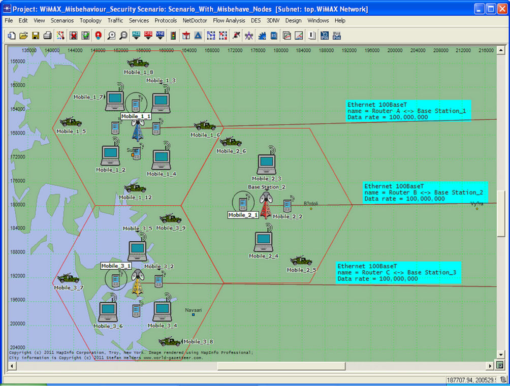
Figure 9. WiMAX subnet with misbehaving node.
In this network the Application Configuration node is defined by using Application Specifications type. Here we can see that only 3 applications are defined in Application Definition attributes, these applications are File Transfer (Light Load), Video Conferencing (Light Load) and Voice over IP Call (PCM Quality). It is clear that all the three applications Voice, Video and Data are supported by the Subscriber Stations (SSs) [11].
Parameters Associated with profile configuration node is shown in Figure 12.
The “Profile Config” node can be used to create user profiles. These user profiles can then be specified on different Subscriber Station (SS) nodes in the network to generate application layer traffic. The applications defined in the “Application Config” objects are used by this
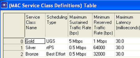
Figure 10. WiMAX configuration node parameters.
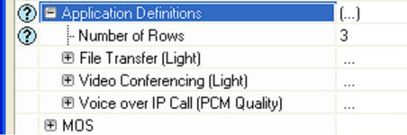
Figure 11. Application configuration node parameters.
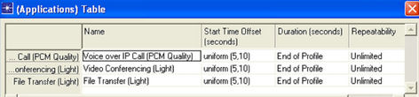
Figure 12. Profile configuration node parameters.
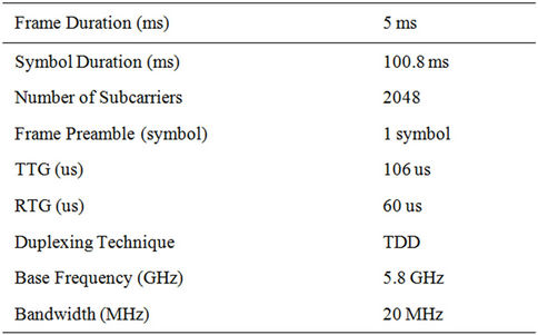
Table 1. OFDM PHY profile.
object to configure profiles. Therefore, applications must be created using the “Application Config” object before using this object. The traffic patterns followed by the applications can also be specified as well as the profiles can be configured on this object.
Parameters Associated with WiMAX Base Station (BS) is shown in Table 2 and Figure 13.
The maximum power transmission from the Base Station is kept at 2 Watts. PHY Profile Attribute specifies the PHY profile to be used for all communications from/ to this MAC. A BS node and its associated SS nodes should be configured with the same PHY profile. The PHY profile references a parameter set configured on the WiMAX Configuration node. The PHY Profile Type attribute defines the class of the PHY profiles. A BS node and its associated SS nodes should be configured with the same PHY profile type. There are two PHY Profile types SC (Single Carrier) and the OFDM (Orthogonal Frequency Division Multiplexing); here The PHY Profile Type is used in OFDM mode.
The Classifier Definition Attributes are shown in Figure 14. In this attribute three rows are present, which provides support to three Service Classes (i.e. GOLD, SILVER and BRONZE) defined in WiMAX Configuration Node. The match value for three service classes is set to Excellent Effort, Streaming Multimedia and Best
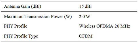
Table 2. Base Station (BS) parameters.
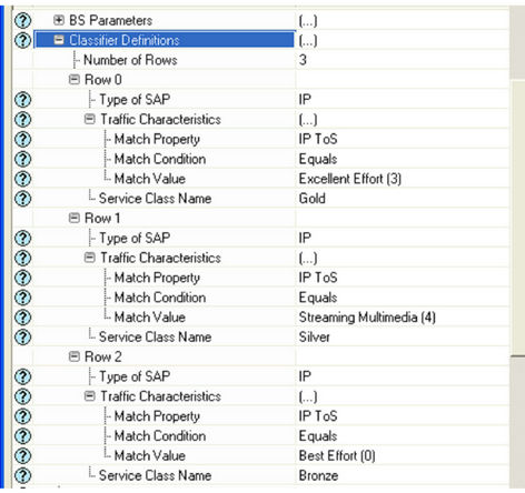
Figure 13. Base Station (BS) classifier definitions.
Effort respectively.
Parameter associated with Subscriber Station (SS) is shown in Figures 14 and 15; this node provides the client functionality. On this node the WiMAX Parameters and Applications attributes are need to be set. The WiMAX Parameters attribute are shown in Figure 14.
The WiMAX Parameters are all similar to WiMAX Parameters of Base Station (BS); here the Antenna Gain is kept to –1 dBi, the Classifier Definitions are same as BS Classifier Definitions and is described in Figure 14. The Maximum Transmission Power is set to 0.5 watts. The SS Parameters is shown in Figure 15.
In SS Parameters the BS MAC Address attribute used by a SS MAC to identify its serving BS MAC. If set to “Distance Based” SS node will use the MAC address of the nearest BS node. This attribute replaces the BS discovery procedure achieved during network entry of a SS node. Once the BS is identified by this attribute, it will be used by the SS for the entire simulation duration.
The Downlink Service Flows attribute specifies important characteristics. Downlinks originate at the BS and terminate at this SS node. Several downlinks may be configured. There should be only one downlink service flow to this node with a given service class name. This attribute is shown in Figure 16.
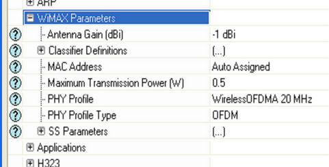
Figure 14. Subscriber station WiMAX parameters.
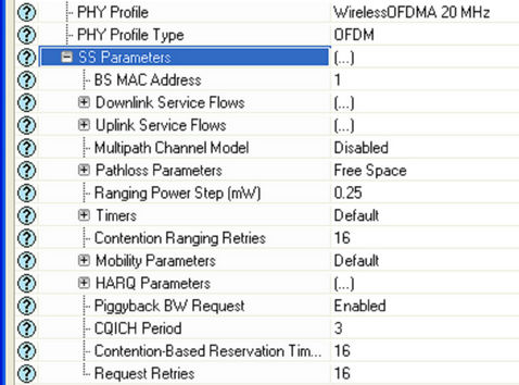
Figure 15. SS parameters.
The modulation schemes need to be set for an individual client, which is shown in Modulation and Coding attribute for all three service classes (i.e. GOLD, SILVER and BRONZE). Also the Average SDU Size is 1420 bytes and Buffer Size is kept at 10 MB to overcome Buffer Overflows. Similarly, Uplink Service Flows attributes are shown in Figure 1 7.
The Multipath Channel model is disabled and the Path loss Parameters is set to Free Space.
5. Result Analysis
In this model the effect of Misbehaving Node is need to be analyzed. The kind of misbehavior simulated is that the node does not respect the MAC layer protocols; it transmits the traffic it has as soon as it needs. On the other hand, the other nodes are well behaved nodes; they wait until all they sense the channel is idle before start transmit [11].
In this section the result analysis is done by showing the graph for the global WiMAX parameters, also the results with respect to each node are analyzed. Firstly, the global analysis is done after that the node analysis is done.
The graph of WiMAX Delay (sec) is shown in Figure 18.
Since misbehaving node continuously send the packet at the Constant Bit Rate (CBR). There is flooding of packet in the channel because this node does not listen and respond any one, simply sent the packets. Hence due to this delay in the network is high as compared to the scenario without misbehavior node. In the figure this is indicated by blue bar graph. The graph for Download Response Time and Upload Response Time is shown in Figures 19 and 20 respectively.
This parameter is only present in Data Servers, in this
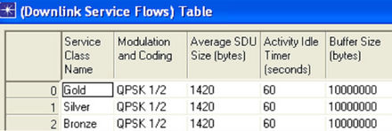
Figure 16. Downlink service flows.
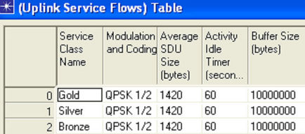
Figure 17. Uplink service flows.
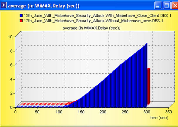
Figure 18. Average WiMAX Delay (sec) with and without misbehaving node.
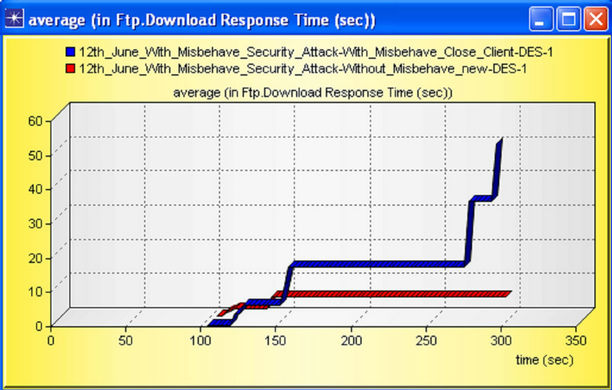
Figure 19. Download Response Time (sec) with and without misbehaving node.
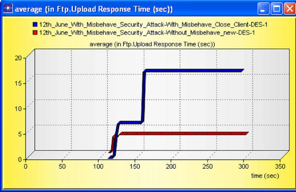
Figure 20. Upload Response Time (sec) with and without misbehaving node.
case FTP Servers, this parameter describes the interval between request send by client or server and the response which is getting back by either client or server. From the figure we can justify that, because of the present of misbehaving node the response time increases, and the network performance reduces. One observation is important between them; misbehavior nodes impacted more in case of download i.e. DL packets are destroyed or upset more from BS to SS. This result can be verified by wastage of packets in UL and DL which is shown in Figures 21 and 22 and respectively.
Traffic sent and received is an important outcome for this network design; traffic sent by Base Station (BS) is near about same, but the traffic received at the BS is so high i.e. again we can say that misbehavior node is highly affected in DL (BS to SS) operation. The traffic sent and traffic receive graph is shown in Figures 23 and 24 respectively.
The graph for WiMAX global Throughput (packet/sec) is shown in Figure 25.
From the figure it is clear that misbehavior node continuously send the unwanted packet in the network channel so every Subscriber Stations (SS) load, sometime increases or sometime decreases, but the global throughput should be high due to unwanted load.
We have already seen that the global throughput is increases because every BS performance also affected by misbehaving node. The Throughput at (BS) is shown in Figure 26.
The Throughput (packets/sec) for WiMAX client is
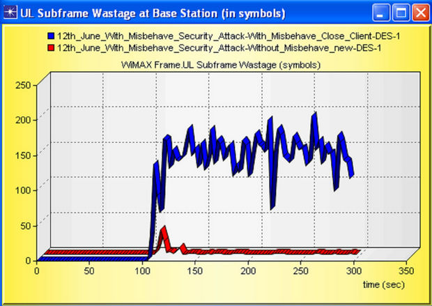
Figure 21. UL Subframe Wastage (in symbols) with and without misbehaving node.
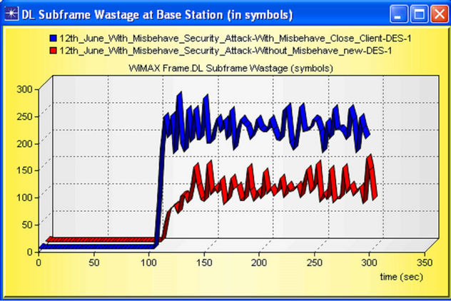
Figure 22. DL Subframe Wastage (in symbols) with and without misbehaving node.
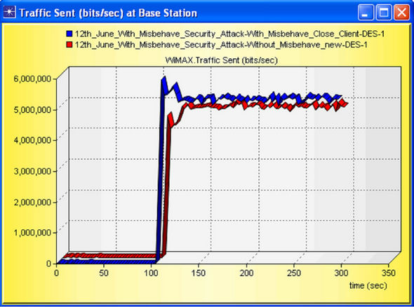
Figure 23. Traffic Sent (bits/sec) by Base Station (BS).
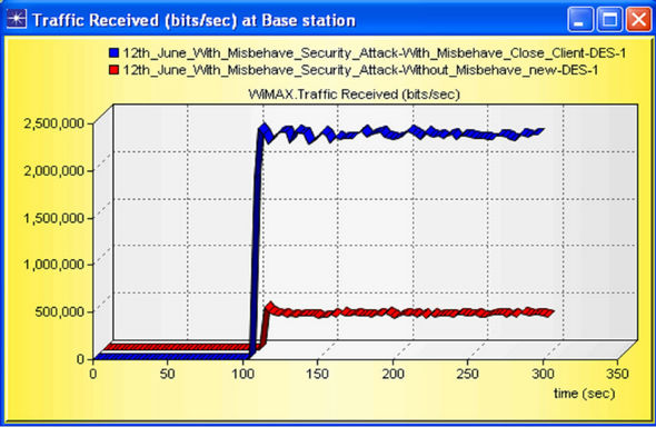
Figure 24. Traffic Received (bits/sec) at BS.
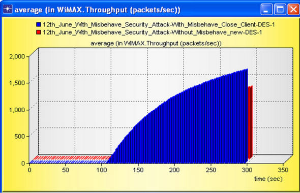
Figure 25. Average WiMAX Throughput (packets/sec) with and without misbehaving node.
shown in Figure 27, as discussed above the misbehaving node randomly generates the network noise by increasing random packets, thus overall throughput at the Subscriber Station (SS) on account of misbehaving node is high.
Our result gives better conclusion about one of the Base Station’s packet dropped. As Shown in Figure 28 data dropped is increases with time by considering Misbehaving Node which is shown by blue graph in figure, and near about 0 in case of without Misbehaving Node.
WiMAX Subframe MAC overhead is shown in Figure 29.
In above figure we have seen the effect of MAC Overhead i.e. in the presence of misbehaving node; MAC Overhead is so high then without misbehaving node. All the above result has been taken for verification of detection and protection for misbehavior node attack.
6. Detection and Protection for Misbehavior Attack
In this proposed algorithm Base Station (BS) is able to detect unauthorized user on the basis of minimum and maximum time is required for real wireless communication. This approach will detect both fixed and mobile misbehavior node attacks. The valid user (node) will communicate without any impediment and at the same time unauthorized user has been blocked by BS [11,12].
7. Flow Chart for Detection and Protection for Misbehavior Attack
In WiMAX scenario all the communication has been done through BS i.e. clients send the request or demand the request with UL (Uplink) and received the data with
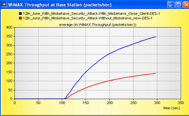
Figure 26. Throughput (packets/sec) at Base Station (BS).
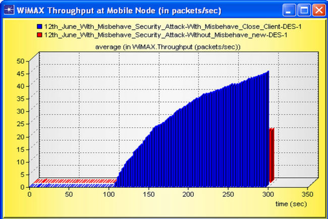
Figure 27. Throughput (packets/sec) on Subscriber Station (SS).
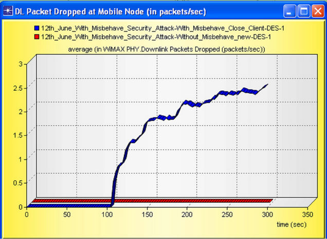
Figure 28. WiMAX Packet dropped (in packets/sec).
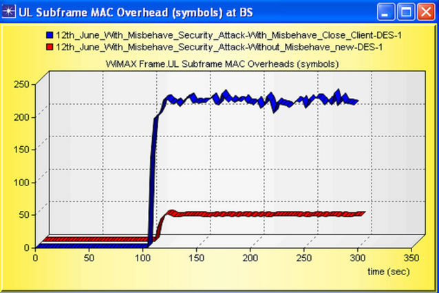
Figure 29. Subframe MAC overhead with and without misbehaving node.
DL (Downlink) through BS only. In our propose case study all the communication has been done through BS i.e. node A and valid client node B. The standard time has been defined at BS for valid communication and all the information and data are stored in data base. The following step will be considered for our proposed research. The flow of our proposed algorithm is given in Figure 30.
In our case study A = Base Station, B = Valid Client, M = Misbehavior Node and R = Repeat condition.
Case 1: The total time TTotal(min) = TRTS(min) + TCTS(min) + TACK(min) will be stored at BS before communication is start between valid node A and BS B.
Case 2: Node A and Node B wants to communicate with each other (UL and DL).
Case 3: Calculate the total time TTotal = TRTS + TCTS + TACK + TΔTh between authorized user (B) and base station (A).
Case 4: Compare the Total time and TTotal(min), if TTotal(min) is less than or equal to Total time then BS judge that the demanding node is valid node i.e. node A is authorized node. If the condition is reverse BS stop responding to node B and node B treated as an unauthorized or misbehavior node.
Case 5: In the duration of authorized communication misbehavior node M wants to communicate with BS i.e. node A. The misbehavior node only able to fetch or demand the data if T’total is less then equal to TTotal(min).
Case 6: If the condition is reversed then stop respondI. Flow Chart
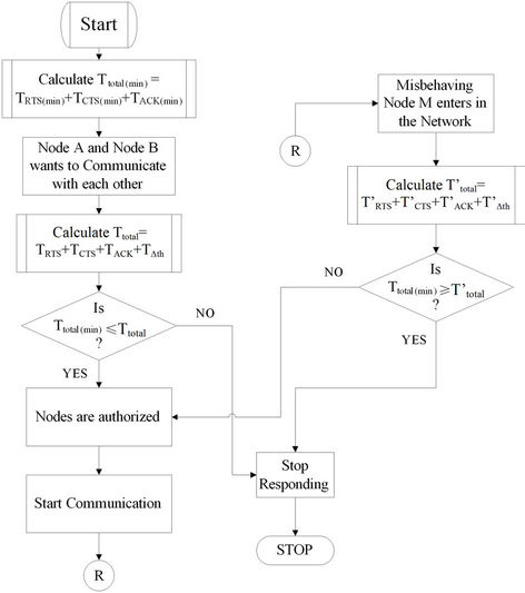
Figure 30. Flow chart for detection and protection from misbehavior node attack.
ing the node M by BS B and resend to initial condition.
8. Conclusion
In this paper we have investigated the performance analysis of misbehavior node attack in WiMAX system. In the first case study we have compared the result with and without misbehavior node attack (Network Layer) in WiMAX Network. We have conduced that why some time network performance is improved (Increased the Throughput) i.e. we can analyzed or detect that some unwanted client or users may aces our network. In the last phase of first case study we have observed that due to misbehaving node, the performance of entire network is degraded by increasing delay in the network and the unwanted throughput in the network increases. In the second case study, we have proposed an algorithm to detect misbehavior node attack as they can protect the unwanted communication from misbehavior node attack. Our approach is very simple for detection and fortification analysis because this proposal based on simple mathematical time based analysis.
9. Future Scope
The current research approach helps to detect unwanted client and we can minimize or overcome the effect of misbehavior node so that we can protect network layer attack and packet flooding. In future we can also do the application Layer attack for DDoS with Markov Model and selfish node attack.
REFERENCES
- R. Jha and U. D. Dalal, “Security Analysis of WiMAX Network: With Misbehavior Node Attack,” World Congress on Communication Technology, Mumbai, 11-14 December 2011, pp. 391-398.
- S. A. Ilyas, “WiMAX Standards and Security,” CRC Press, London, 2008.
- R. Jha and U. D. Dala, “A Journey on WiMAX and Its Security Issues,” International Journal of Computer Science and Information Technologies, Vol. 1, No. 4, 2010, pp. 256-263.
- N. Vassileva and Y. Koucheryavy “Guard Capacity Implementation in OPNET Modeler WiMAX Suite,” Ultra Modern Telecommunications & Workshops, St. Petersburg, 12-14 October 2009, pp. 1-6.
- J. G. Andrews, A. Ghosh and R. Muhammad, “Fundamentals of WiMAX Understanding Broadband Wireless Networking,” Prentice Hall, Saddle River, 2007.
- R. Jha and U. D. Dala, “Location Based Performance of WiMAX Network for QoS with Optimal Base Stations (BS),” Wireless Engineering and Technology, Vol. 2, No. 3, 2011, pp. 135-145. doi:10.4236/wet.2011.23020
- F. Ohrtman, “WiMAX Handbook Building 802.16 Wireless Networks,” McGraw-Hill, Boston, 2005.
- R. Jha and U. D. Dala, “Resource Allocation Downlink OFDMA in WiMAX Systems,” Proceedings of the 2011 International Conference on Communication, Computing & Security (ACM), Odisha, 12-14 February 2011, pp. 82- 85.
- R. Jha and U. D. Dala, “A Performance of Security Aspets in WiMAX Physical Layer with Different Modulation Schemes,” Communications in Computer and Information Science, Vol. 125, 2011, pp. 443-440.
- S.-Y. Tang, “WiMAX Security and Quality of Service an End-to-End Prospective,” John Wiley & Sons, Hoboken, 2010. doi:10.1002/9780470665749
- R. Jha and U. D. Dala, “WiMAX System Simulation and Performance Analysis under the Influence of Jamming,” Wireless Engineering and Technology, Vol. 1, No. 1, 2010, pp. 20-26. doi:10.4236/wet.2010.11004
- R. K. Jha, A. V. Wankhede and U. D. Dalal, “Investigation of Internet Key Exchange (IKE) in Terms of Traffic Security with Gateway Security (GSE) in WiMAX Network,” IJCA Special Issue on Network Security and Cryptography (NSC), No. 1, 2011, pp. 59-66.