Journal of Water Resource and Protection
Vol.5 No.6(2013), Article ID:33249,9 pages DOI:10.4236/jwarp.2013.56063
Prediction of Water Logging Using Analytical Solutions—A Case Study of Kalisindh Chambal River Linking Canal
Civil Engineering Department, Malaviya National Institute of Technology, Jaipur, India
Email: dnkongre@gmail.com, rgoyal_jp@yahoo.com
Copyright © 2013 Dipak N. Kongre, Rohit Goyal. This is an open access article distributed under the Creative Commons Attribution License, which permits unrestricted use, distribution, and reproduction in any medium, provided the original work is properly cited.
Received April 9, 2013; revised May 9, 2013; accepted May 31, 2013
Keywords: Waterlogging; Seepage; Analytical Solutions; GIS; 3D Analyst
ABSTRACT
The canals are designed to transport water to meet irrigation and other water demands or to divert water from surplus basins to deficient basins to meet the ever increasing water demands. Though the positives of canal network are increase in agricultural output and improvement in quality of life, the negatives of canal introduction and irrigation, along its route, are inherent problems of water logging and salinity due to seepage from canals and the irrigation, when not managed properly. To plan strategies to prevent waterlogging and salinity, it is necessary to predict, in advance, the probable area which would be affected due to seepage. This paper presents a methodology to predict the area prone to water logging due to seepage from canal by using 2D seepage solutions to 3D field problem. The available analytical solutions for seepage from canals founded on pervious medium and asymmetrically placed drains, have been utilized. The area, prone to waterlogging, has been mapped using GIS.
1. Introduction
Growing need of food and fibre for increasing population needs more agricultural land to be irrigated, necessitating the transportation of water through canals from the reservoirs, wherever possible. In India there is a large variation in the rainfall in both time and space leading to scenario of droughts and floods simultaneously. To overcome this challenge of droughts and floods and to provide water to the water deficient regions, the Government of India has muted river interlinking project. The Parbati Kalisindh Chambal river interlinking is a part of peninsular river interlinking project. The surplus water of Parbati and Kalisindh basins is to be diverted to meet the demand in upper Chambal basin [1-4]. The construction of this link would surely benefit the recipients of additional water but the problems of water logging and salinity due to seepage from canals and irrigation need consideration for planning preventive measures. In the northwest part of Rajasthan state, canal irrigation was introduced after commissioning Indira Gandhi NaharPariyojna (IGNP) to irrigate nearly 2.2 million ha of arid land. It has increased the food production but it also introduced waterlogging and secondary salinization problems [5,6]. The size of the waterlogged area in the year 1998 was 17,220 ha in stage I of the project and 800 ha in stage II of the IGNP project [7]. The major reasons for water logging and salinization in this area are indiscriminate use of irrigation water, canal seepage, sandy texture and absence of natural surface drainage [8]. The same factors have led to rise in water table in the north-west region of Haryana, India and water logging problems. About 500,000 ha area is waterlogged and unproductive [9,10]. It is estimated that in India nearly 8.4 million ha is affected by soil salinity and alkalinity, of which about 5.5 million ha is also waterlogged [11]. In the states of Bihar, Gujarat, Madhya Pradesh, Jammu & Kashmir, Karnataka, Kerala, Maharashtra, Odisha and Uttar Pradesh 117.808 thousand hectare waterlogged area has been approved for reclamation under command area development program by Ministry of Water Resources [12]. The total waterlogged area in canal command in India, in the year 1996, was around 2.189 million ha [13]. More than 33% of the world’s irrigated land is affected by secondary salinization and/or waterlogging [14]. These statistics clearly show the need to manage canal seepage and irrigation to reduce water logging and secondary salinization.
Canal linings are used to reduce seepage. Yao et al. [15] studied the effect of canal lining and multilayered soil system on canal seepage and found that the combination of canal lining and a low-permeability layer below the canal is effective in reducing seepage. Though perfect canal lining can prevent seepage loss, but cracks can develop in the lining, and the performance of the canal lining deteriorates with time [16]. Wachyan and Ruston [17] studied several canals and concluded that significant seepage losses occur even in a well maintained canal with good lining.
Seepage from canals can be calculated by physical, empirical and mathematical (analytical and numerical) techniques [18-21]. Empirical formulae and graphical solutions are generally used to estimate seepage losses from proposed canals whereas the direct measurements such as inflow-outflow method, ponding method, seepage meter method are used to evaluate seepage from existing canals [22,23]. Various empirical formulae for estimating seepage are discussed by Bakri and Awad [24]. The seepage losses from irrigation canals with different lining materials, subsurface flow and subsurface storage along the canal, channel longitudinal slope, have been estimated by different researchers using direct measurements or electrical resistivity [25-28]. Analytical and electrical analogy solutions of seepage problems related to irrigation canals have been presented by many authors. Zhukovsky was the first to introduce the method for solution of problems involving unconfined seepage using a function which is now well known as Zhukovsky’s function. Vedernikov gave an exact mathematical solution to unconfined, steady-state seepage from a triangular and a trapezoidal canal in a homogeneous, isotropic, porous medium of large depth [29]. Vedernikov [30] solved the problem of seepage from a canal to the symmetrically placed collector drainages, neglecting the effect of the canal water depth and side slopes. Many Russian investigators analysed solutions for rectangular, triangular channel of zero depth for different boundary conditions [31,32]. The solution for seepage problem for a rectangular canal was provided by Morel-Seytoux [33]. Sharma and Chawla [34] presented solution of the problem of seepage from a canal to vertical and horizontal drainages, symmetrically located at finite distances from the canal, in a homogenous medium extending up to a finite depth. The water depth in the canal was assumed negligible in comparison to the width. Exact solution of the problem of seepage from a canal in a homogeneous medium to asymmetric drains located at finite distance from the canal was provided by Wolde-Kirkos and Chawla [35]. Goyal [36] provided solutions for seepage from canals founded on pervious soil with asymmetric drainages. Algorithm to solve the nonlinear integral equations to obtain the value of seepage discharges and profile of the free surface was developed. The computer program developed for solutions generates the coordinates of seepage profile and estimates the seepage quantities. Ilyinsky et al. [37] have carried out a comprehensive review of analytical solutions for seepage problems and observed that though numerical techniques have become more significant in solving practical problems of seepage theory but analytical methods are necessary not only to develop and test the numerical algorithms but also to gain a deeper understanding of the underlying physics, as well as for the parametric analysis of complex flow patterns and the optimization and estimation of the properties of seepage fields. Swamee et al. [38] obtained an analytical solution for seepage from a rectangular canal in a soil layer of finite depth overlying a drainage layer using inversion of hodograph and conformal mapping technique. Bardet and Tobita [39] presented finite difference approach for calculating unconfined seepage using spread-sheets. They derived the finite difference equations using flux conservation in the general case of non-uniform and anisotropic permeability and boundary conditions. The flow lines and free surfaces can be obtained using their method but the method cannot be adopted when systems of equations become large.
Sharma and Shakya [40] applied the Bousinessq equation using the Laplace transform and Fourier cosine transform in determining the phreatic surface elevation in horizontal unconfined aquifers along the canal sides. An exact analytical solution for the quantity of seepage from a trapezoidal channel underlain by a drainage layer at a shallow depth obtained by using an inverse hodograph and a Schwarz-Christoffel transformation was presented by Chahar [41]. It provides a set of parametric equations for the location of phreatic line. To reduce the conveyance losses due to seepage, many researchers have provided methods to design the canals for minimum seepage [20,38,42,43]. Ayvaz and Karahan [44] provided spreadsheet application of three-dimensional (3D) seepage modeling with an unknown free surface. They derived governing equation using finite differences method in the general case of anisotropic and non-uniform material properties and variable grid spacing and also modified it by the extended pressure method. Only one finite difference equation was applied to the solution domain instead of derivation of additional finite difference equation to impervious boundary conditions, inclined interfaces, etc. Solution to seepage under the dam has been provided using this method. Ahmed and Bazaraa [45] investigated the problem of seepage under the floor of hydraulic structures considering the compartment of flow that seeps through the surrounding banks of the canal. A computer program, utilizing a finite-element method and capable of handling (3D) saturated-unsaturated flow problems, was used. The results produced from the two-dimensional (2D) analysis were observed to deviate largely from that obtained from 3D analysis of the same problem, despite the fact that the porous medium was isotropic and homogeneous. These solutions may be suitable for a dam with finite length but may not prove suitable when it is applied to canals which are longer in length.
Though, lot of literature about solution to the seepage problem and to estimate seepage is available, no case study about the application of these solutions to map the area, susceptible to waterlogging, has been reported.
The main objectives of this paper are to use available analytical solution to estimate the probable waterlogged area and to develop methodology for adopting 2D solutions to 3D field problem.
2. Analytical Solution
The analytical solution for the seepage problem has been provided by Goyal [36] for the seepage from canals with negligible water depth, founded on finite pervious media and asymmetrically placed drains on the either sides. It has been done using conformal mapping and defining free surface using Zhukovsky’s function. Integral equations were obtained by using Zhukovsky’s function and Schwarz-Christoffel transformation. It is assumed that the soil medium below the canal is homogeneous and isotropic. The seepage flow is assumed to be steady and furthermore the water depth in the canal and drainages and the level of surface does not fluctuate with time. The soil within the seepage domain is saturated. It is also assumed that there is no infiltration/evaporation in the seepage domain under consideration. Problem of seepage profile has been defined in Figure 1.
Where, B is the base width of the canal, h1 and h2 are the difference of levels between free surface level in the canal and the drains on the right and left hand sides respectively. L1 and L2 are the horizontal distances of the drains from the edge of the canal and T is the depth of impervious layer/bed rock below the canal bed.
To solve the equations for seepage profiles and the seepage losses at a cross section, using this analytical solution, the dimensionless parameters L1/h1, L2/h1, B/h1, h2/h1 and T/h1 at that section are required. These are determined from the known values of L1, L2, B, T, h1 and h2. The user interactive computer program written in C++, on providing the input parameters, calculates profiles of
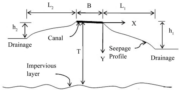
Figure 1. Definition sketch of the seepage problem.
the phreatic surfaces on the left and right sides of the canal and the seepage discharge for that cross section.
The solution obtained is only for a 2D section under consideration. The field problem being a 3-D problem, it is required that the 2D solutions are obtained at different sections along the alignment. Therefore the third dimension of the canal, i.e. the length, is discretized by taking sections at regular intervals along its length. The solutions obtained for each section can then be combined to get the solution for a problem in 3D space.
Geographical Information System (GIS) is a very efficient tool for spatial data management and analysis. Mapping the canal, the drains and the sections and then extracting the required data of L1, L2, B, T, h1and h2, for each section, for calculations of input parameters can be efficiently done using GIS. Its versatility in spatial interpolation can be utilized to interpolate the 2-D solutions at each section to get a 3-D solution and then to map the waterlogged area.
3. Study Area
The Parbati-Kalisindh-Chambal (PKC) river interlinking project is one of the projects proposed by National Water Development Agency (NWDA), India [1,2]. The study area, surrounding the Kalisindh-Chambal link canal, lies between 23˚29'N and 25˚0'N latitudes, and 75˚20'E and 76˚17'E longitudes. It is bounded by the river Chambal and its tributaries on the west and south west, River Kalisindh and its tributaries forms eastern and south eastern boundary. In its feasibility report, NWDA has prepared feasibility for two of the proposed alternative routes. The alignment of canal between Parbati and Kalisindh rivers is same in both routes. The remaining alignment differs only while joining rivers Kalisindh and Chambal. The two proposed alternative routes are Joining storage dam at Kundaliya on the river Kalisindh with full reservoir level (FRL) of 370 m to:
1) Rana Pratap Sagar dam on river Chambal with FRL of 352.81 m by a 108 Km long gravity canal and 5.25 Km long tunnel, or 2) Gandhi Sagar, with FRL of 399.89 m, on river Chambal involving gravity canal of 76 Km and 20 Km pipelines and intermediate reservoirs with lift of about 50 m. This requires a net power of about 20 MW/annum [1].
Out of the above two, the first alternative requiring no power and maximum length of open channel has been considered for the seepage analysis. The part of the PKC project between Parbati river and Kalisindh river as well as the second route between Kalisindh and Chambal rivers which to a large part coincides with first route and thereafter consists of small reservoirs and tunnels is not being considered for analysis. The alignment has been detailed by NWDA in Technical report in 2004. The alignment passes through the area covered in the Survey of India Toposheets numbered 45P, 46M, 54D and 55A. It mainly passes through Shajapur district of Madhya Pradesh, Jhalawar, Kota and Chittaurgarh districts of Rajasthan. Kalisindh-Chambal link and various districts are shown in Figure 2. The hydrogeological fault line on northern side between river Chambal downstream of Rana pratap Sagar and river Kalisindh closes the study area. The study area is drained by rivers Kalisindh and its tributaries, rivers Ahu and Kanthili, Amajar and Takli. These rivers are also shown in Figure 2.
The study area is characterized by high hills on south west side and is sloping towards north east. The digital elevation map of the area and the alignment of proposed link are as shown in Figure 3. The highest and the lowest elevation in the area are 561 m and 187 m above mean sea level.
4. Methodology
The analytical solution of the seepage problem, as defined in Figure 1 and presented by Goyal (1994), needs the distances of the drains from the edge of the canal, the thickness of porous media up to the impervious layer and the elevation differences between the canal bed and the drains to define the boundary conditions. To extract this information the canal alignment was mapped using the drawings in the Technical Study under feasibility report of PKC link project. The rivers, viz., Kalisindh, Chambal and their tributaries forming the boundary and the rivers, viz., Ahu and Kanthili, Amajar and Takli draining the area have been mapped using existing maps of the area.
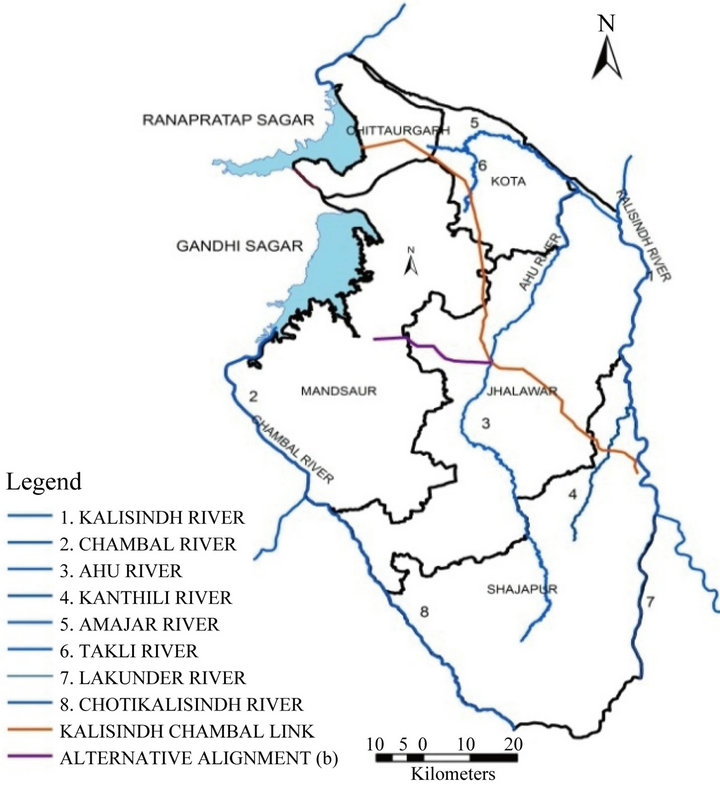
Figure 2. Study area.
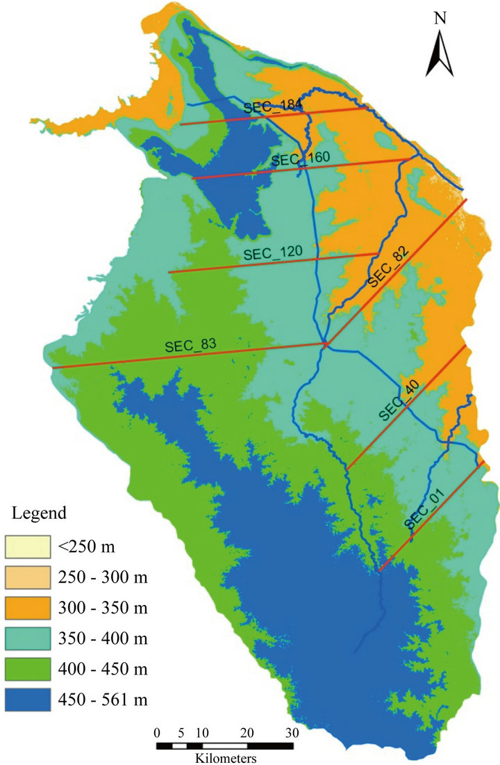
Figure 3. DEM of study area.
The cross sections have been marked at every half kilometer along the alignment. The cross sections start from the drain/reservoir on the left side of alignment cross the alignment and end at the drain on its right side. The Kalisindh-Chambal link alignment can be taken as made of two straight segments neglecting minor deviations. The cross sections have been marked in two sets. In each set, the cross sections have been kept parallel so that solution of one cross section doesn’t interfere with the solution of other adjacent section. The sample cross sections are also shown in Figure 3. It is assumed that at the change of direction in alignment the sections which intersect with other sections don’t have impact on the final solutions.
The area has complex geology and has alluvium, weathered to compact sandstone, limestone, shale and basalt at different depths. The hydrogeological units were idealized by combining similar nature of layers as single layer and conceptual hydrogeologic model was developed. The compact shale has hydraulic conductivity less than 1/10th of other formations and therefore shale layer has been taken as impermeable layer. The borehole records of Jhalawar, Kota and Chittaurgarh districts of Rajasthan [46], the details of various hydrogeological formations at piezometer locations in Madhya Pradesh and the district resource maps of all the districts in the area have been used to create layers of hydro geological formation. The average depth of impervious shale layer from the canal bed for each section was extracted using spatial analyst tool and 3D feature of cross section, in GIS environment. The given analytical solution provides the seepage profile coordinates with origin at the edge of the canal bed. The elevations of various points along the section are required to determine the difference of elevations between the ground level and the seepage profile. These can be extracted from digital elevation models of the area. The ASTER dataset being the latest Global Digital Elevation Model (GDEM) has been used in the study. The GDEM is produced with 30 meter postings and has Z accuracies generally between 10 m and 25 m root mean square error [47]. The ASTER dataset referring to latitudes and longitudes of the study area was downloaded from the ASTER web site. The mosaic of downloaded elevation datasets was made in GIS to get the digital elevation model for the area. The DEM of the area using ASTER data set is shown in Figure 3.
The elevations of the ground level and the impervious layer along a section can be extracted in ArcGIS by creating 3D features of the sections which are 2D features. The 3D features were created using 3D Analyst tools in ArcGIS and were then used to get the profiles of ground surface. ArcGIS provides tools to create profile of a particular layer along a line of interest. This profile can be obtained as a graphical representation of distance versus elevation or can be exported as table in excel format. This technique was used to extract the information regarding elevations of ground surface and impervious surface for each section. The sample profile of ground at cross section no. 40 is shown in Figure 4.
The distance along the cross section from its starting point is given on X axis and the elevations are shown on Y axis. The vertical scale is exaggerated. The data set exported in excels format gives the elevations of points approximately at 28 to 30 m interval. The distances of drains, on left and right sides, from the edge of the canal i.e. L1 and L2 were calculated by using geographical coordinates (in meters) of the points at the intersections of the cross sections with the drains and the canal. The difference of elevations between the canal bed and the drains, h1 and h2, have been computed by using the elevations of canal bed and left and right end points of the sections. The elevations of the bed of the canal at each section, along the alignment were calculated using information in the Technical Report of the proposals. The depth of impervious layer from the canal bed, T, at each section was calculated by finding the difference of elevation of canal bed and average elevation of impervious layer at that section. The data of L1, L2, h1, h2 and T for each section were tabulated for calculation of input parameters. The details of L1, L2, h1 and h2 for some sample cross sections are presented in Table 1.
In the case of Kalisindh Chambal Link, it is evident from the DEM given in Figure 3 that the elevations of the drains on the left side are higher than the elevation of canal bed at almost all the cross sections. Therefore the value of h1 works out to be negative. Since the program developed does not work for the negative h1 and h2 values, it was not possible to use the program for calculating profile on both sides. It was found that the depth of left hand did not make any significant difference in profile of right hand side and vice-versa and therefore a uniform depth of 1 m for left hand side was artificially chosen to obtain the profile of only right hand side. Profile obtained for left hand side was ignored. Table 2 shows the details of calculated input parameters for some sample cross sections.
The input text file for all the sections was prepared to run the program. The computer program developed for the solution of seepage problem can be run in two modes, i.e. obtaining result on screen for single cross section or for multiple cross sections using input and output text files. The program outputs present the coordinates of
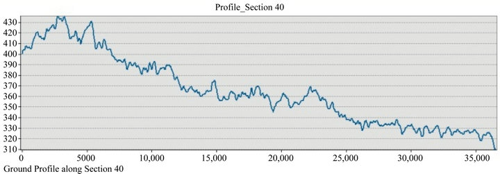
Figure 4. Sample profile at cross-section no. 40.
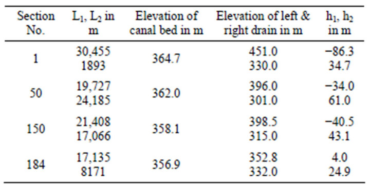
Table 1. Selected cross-section details.
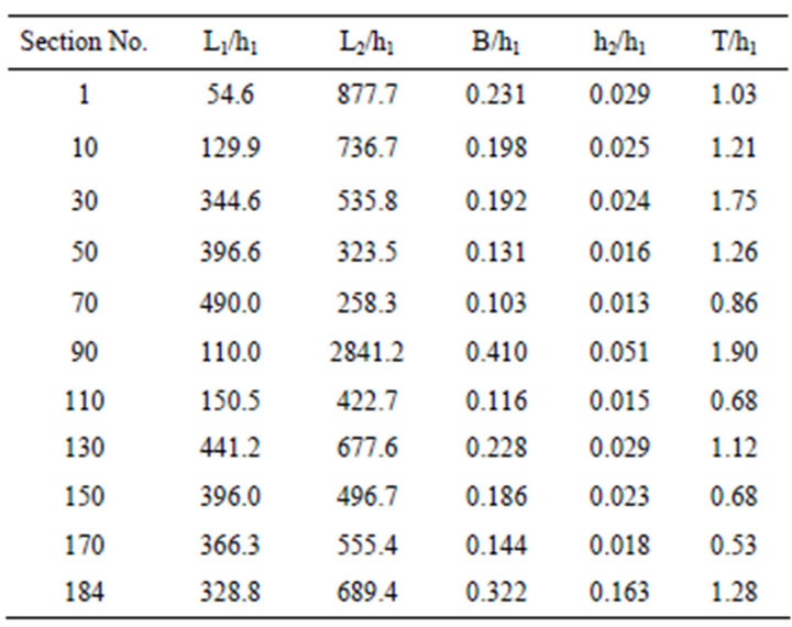
Table 2. Calculated input parameters.
seepage profile, with origin at the edge of canal, in terms of non dimensional ratios x/L and y/h. Where x and y are the horizontal and vertical distance of the seepage profile form the origin, L is length of cross section on one side of the canal and h is the difference of elevation of canal bed and the drain on that side. The program also calculates the rate of seepage. The output of seepage profile coordinates, required for plotting water logged area, was used for further processing. Sample output for one set of input parameters is shown in Figure 5.
The output of the program was post processed to obtain the data for plotting in GIS. The distances at each output point from origin of its coordinate axis and the depth of seepage profile were calculated. The elevations of seepage profile were computed by subtracting the depth of seepage profile from the elevation of canal bed. The difference between the ground elevation and the seepage profile elevation at the points, at an approximate spacing of 28 to 30 m, was calculated for each section. This difference determines whether the point is getting waterlogged or not. The criterion for classification of waterlogged areas as laid down by [48] has been used for classification. As per this classification, the area is waterlogged, if the water table is within 2 m of land surface, potential area for waterlogging, when it is between 2 to 3
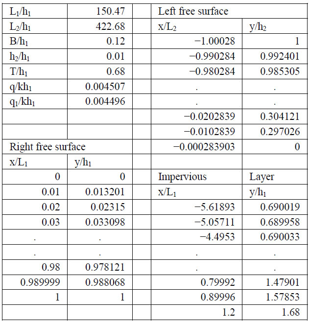
Figure 5. Sample output.
m and safe if it is below 3 m.
Layer of points, at approximately 28 to 30 m spacing along every section, with difference of elevation of ground and elevation of seepage profile as attribute, was created in GIS. The difference between elevation of ground and elevation of seepage profile was spatially interpolated. The raster output was then reclassified as per the MOWR classification of water logged area.
5. Result
The results show that the total area which is prone to water logging is around 256 Sq. Km out of the area of 1846 Sq. Km which lies between the right side of the canal and the boundary. The probable area susceptible to water logging is shown in Figure 6 and the area in square kilometers lying under each category is tabulated in Table 3.
6. Conclusion
The methodology for applying analytical 2D solution of seepage problem to get solutions to 3D field problem with the use of GIS has been presented. The probable waterlogged area for proposed Chambal-Kalishindh link canal has been predicted and mapped using GIS. Since the analytical solution requires minimal input data which is readily available, methodology could be adopted to quickly do a preliminary analysis. The methodology is likely to be inaccurate where ever there is change in alignment however the variations could be insignificant. Using the methodology it has been predicted that an area of 214.36 Sq. Km is likely to be waterlogged and 42.07
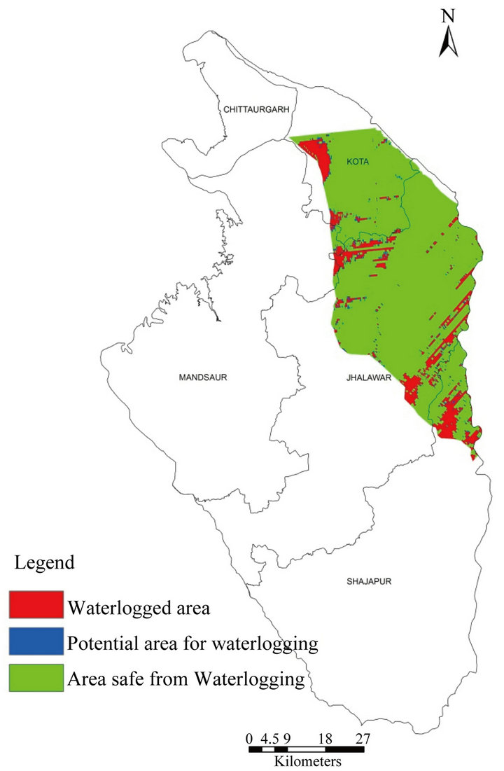
Figure 6. Waterlogged area.
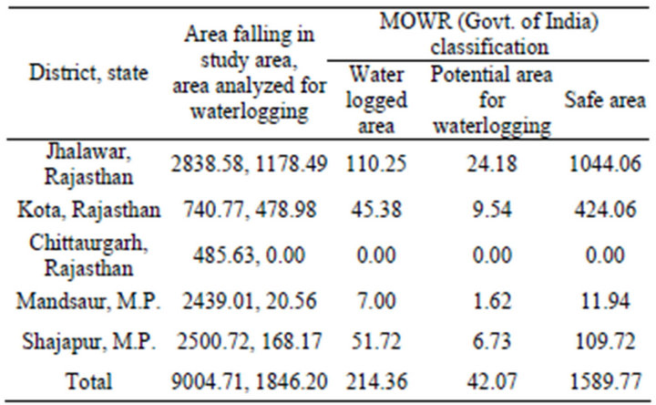
Table 3. Waterlogged area (Sq. Km).
Sq. Km is likely to become potentially waterlogged if the Chambal-Kalisindh link canal project is adopted. However it is important to compare the result with another solution, such as mathematical groundwater model.
REFERENCES
- National Water Development Agency (NWDA), “Feasibility Report of ParbatiKalisindh Chambal Link Project,” 2004. http://www. nwda. gov.in
- C. D. Thatte, “Inter-Basin Water Transfer for Augmentation of Water Resources in India—A Review of Needs, Plans, Status and Prospects,” 2006. http://hdr.undp.org/en/reports/global/hdr2006/papers/cdthatte_interbasin_watertransfer_india. pdf
- J. Bandopadhyay and S. Parveen, “The Interlinking of Indian Rivers: Some Questions on Scientific, Economic and Environmental Dimensions of the Proposal,” 2008. http://www.soas.ac.uk/water/publications/papers/file38403. pdf
- N. Pasi and R. Smardon, “Interlinking of Rivers: A Solution for Water Crisis in India or a Decision in Doubt?” The Journal of Science Policy and Governance, Vol. 2, No. 1, 2013, pp. 1-42. http://www.Sciencepolicyjournal.org/current-edition.html
- A. N. Arora and R. Goyal, “Groundwater Model of Waterlogged Area of Indira Gandhi NaharPariyojna, Stage I,” ISH Journal of Hydraulic Engineering, Vol. 18, No. 1, 2012, pp. 64-76.
- A. K. Mandal and R. C. Sharma, “Delineation and Characterization of Waterlogging and Salt Affected Areas in A Canal Irrigated Semiarid Region of North West India,” Geocarto International, Vol. 23, No. 3, 2008, pp. 181- 195.
- K. D. Sharma, “Indira Gandhi Nahar Pariyojana—Lessons Learnt from Past Management Practices in the Indian Arid Zone Regional Management of Water Resources,” Proceedings of a Symposium Held during the 6th IAHS Scientific Assembly at Maastricht, IAHS Publications, No. 268, July 2001, pp. 49-55.
- H. S. Shankarnarayana and V. K. Gupta, “Soils of the Region,” In: J. Venkateswarulu and I. P. Abrol, Eds., Prospect of Indira Gandhi Canal Project, ICAR, New Delhi, 1991, pp. 19-35.
- K. K. Dutta and C. de Jong, “Adverse Effects of Waterlogging and Soil Salinity on Crop and Land Productivity in North West Region of Haryana,” Agricultural Water Management, Vol. 57, No. 3, 2002, pp. 223-238 doi:10.1016/S0378-3774(02)00058-6
- A. Singh, S. N. Panda, W. A. Flugel and P. Krause, “Waterlogging and Farmland Salinisation: Causes and Remedial Measures in an Irrigated Semi-Arid Region of India,” 2012.
- H. P. Ritzemaa, T. V. Satyanarayanab, S. Ramanc and J. Boonstraa, “Subsurface Drainage to Combat Waterlogging and Salinity in Irrigated Lands in India: Lessons Learned in Farmers’ Fields,” Agricultural Water Management, Vol. 95, No. 3, 2008, pp. 179-189. doi:10.1016/j.agwat.2007.09.012
- Anonymous, “Annual Report 2011-12,” Ministry of Water Resources, Government of India, New Delhi, 2012, p. 4.
- N. K. Tyagi, “Salinity Management: The CSSRI Experience and Future Research Agenda,” Proceedings of the Jubilee Symposium (25-26 November 1996) at the Occasion of the Fortieth Anniversary of ILRl and Thirty-Fifth Anniversary of the ICLD, W. B. Snellen Ed. ILRl Wageningen, April 1997, pp. 17-26. http://edepot.wur. nl/149440
- A. F. Heuperman, A. S. Kapoor and H. W. Denecke, “Biodrainage—Principles, Experiences and Applications,” Knowledge Synthesis Report No. 6, International Programme for Technology and Research in Irrigation and Drainage, IPTRID Secretariat, Food and Agriculture Organization of the United Nations, Rome, 2002, p. 79.
- L. Yao, S. Feng, X. Mao, Z. Huo, S. Kang, S. and D. A. Barry, “Coupled Effects of Canal Lining and Multi-Layered Soil Structure on Canal Seepage and Soil Water Dynamics,” 2012.
- P. K. Swamee, G. C. Mishra and B. R. Chahar, “Design of Minimum Seepage Loss Canal Sections,” Journal of Irrigation and Drainage Engineering, Vol. 126, No. 1, 2000, pp. 28-32. doi:10.1061/(ASCE)0733-9437(2000)126:1(28)
- E. Wachyan and K. R. Rushton, “Water Losses from Irrigation Canals,” Journal of Hydrology, Vol. 92, No. 3-4, 1987, pp. 275-288. doi:10.1016/0022-1694(87)90018-7
- H. Bouwer, “Theory of Seepage from Open Channel,” Advances in Hydroscience, Vol. 5, Academic Press, New York, 1969.
- A. Mirnateghi and J. C. Bruch Jr., “Seepage from Canals Having Variable Shape and Partial Lining,” Journal of Hydrology, Vol. 64, No. 1-4, 1983, pp. 239-265. doi:10.1016/0022-1694(83)90071-9
- A. R. Kachimov, “Seepage Optimization for Trapezoidal Channel,” Journal of Irrigation and Drainage Engineering, Vol. 118, No. 4, 1992, pp. 520-525. doi:10.1061/(ASCE)0733-9437(1992)118:4(520)
- S. Yussuff, H. Chauhan, M. Kumar and V. Srivastava, “Transient Canal Seepage to Sloping Aquifer,” Journal of Irrigation and Drainage Engineering, Vol. 120, No. 1, 1997, pp. 97-109.
- R. V. Worstell, “Estimating Seepage Losses from Canal Systems,” Journal of Irrigation and Drainage Engineering, Vol. 102, No. IR1, 1976, pp. 949-956.
- A. Sarki, S. Q. Memon and M. Leghari, “Comparison of Different Methods for Computing Seepage Losses in an Earthen Watercourse,” Agricultura Tropica et Subtropica, Vol. 41, No. 4, 2008, pp. 197-205.
- M. W. Bakry and A. B. E. Awad, “Practical Estimation of Seepage Losses along Earthen Canals in Egypt,” Water Resources Management, Vol. 11, No. 3, 1997, pp. 197- 206. doi:10.1023/A:1007921403857
- C. Santhi, R. S. Muttiah, J. G. Arnold and R. Srinivasan, “A GIS-Based Regional Planning Tool for Irrigation Demand Assessment And Savings Using Swat,” Transactions of the ASAE, Vol. 48, No. 1, 2005, pp. 137-147.
- S. K. Singh, C. Lal, N. C. Shahi and C. Khan, “Estimation of Canal Seepage under Shallow Water Table Conditions,” Journal of Acdemic & Industrial Research, Vol. 1, No. 9, 2013, pp. 571-576.
- H. E. M. Moghazi and E. S. Ismail, “A Study of Losses from Field Channels under Arid Region Conditions,” Irrigation Science, Vol. 17, No. 3, 1997, pp. 105-110. doi:10.1007/s002710050028
- R. H. Hotchkiss, C. B. Wingert and W. E. Kelly, “Determining Irrigation Canal Seepage with Electrical Resistivity,” Journal of Irrigation and Drainage Engineering, Vol. 127, No. 1, 1979, 2001, pp. 20-26.
- M. E. Harr, “Groundwater and Seepage,” McGraw Hill, New York, 1962.
- V. V. Vedernikov, “Seepage Theory and Its Application in the Fields of Irrigation and Drainage,” State Press, Gosstroiizdat, 1939.
- P. Y. Polubarinova-Kochina, “Theory of Ground Water Movement,” Princeton University Press, Princeton, 1962.
- V. I. Aravinand S. N. Numerov, “Theory of Fluid Flow in Undeformable Porous Media,” Israel Program for Scientific Translations, Jerusalem, 1965.
- H. J. Morel-Seytoux, “Domain Variations in Channel Seepage Flow,” Journal of the Hydraulics Division, ASCE, Vol. 90, No. HY2, 1964, pp. 55-79.
- H. D. Sharma and A. S. Chawla, “Canal Seepage with Boundary at Finite Depth),” Journal of the Hydraulics Division, ASCE, Vol. 105, No. 7, 1979.
- A. T. Wolde-Kirkos and A. S. Chawla, “Seepage from Canal to Asymmetric Drainages,” Journal of Irrigation and Drainage Engineering, Vol. 120, No. 5, 1994, pp. 949- 956. doi:10.1061/(ASCE)0733-9437(1994)120:5(949)
- R. Goyal, “Seepage from Canals Founded on Pervious Soil with Asymmetric Drainages,” Ph.D. Thesis, University of Roorkee, Roorkee, 1994.
- N. B. Ilyinsky, A. R. Kacimov and N. D. Yakimov, “Analytical Solutions of Seepage Theory Problems. Inverse Method, Variational Theorems, Optimization and Estimates (A Review),” Fluid Dynamics, Vol. 33, No. 2, 1998, pp. 157-168. doi:10.1007/BF02698697
- P. K. Swamee and D. Kashyap, “Design of Minimum Seepage Loss in Non-Polygonal Canal Sections,” Journal of Irrigation and Drainage Engineering, Vol. 127, No. 2, 2001, pp. 113-117. doi:10.1061/(ASCE)0733-9437(2001)127:2(113)
- J. P. Bardet and T. Tobita, “A Practical Method for Solving Free-Surface Seepage Problems,” Computers and Geotechnics, Vol. 29, No. 6, 2002, pp. 451-475. doi:10.1016/S0266-352X(02)00003-4
- S. Sharma and S. K. Shakya, “Rise of Water Table Induced by Seepage from Canal,” In: V. Kumar, M. Kothari and R. C. Purohit, Eds., 37th ISAE Annual Convention, Udaipur, India, 29-30 January 2003, and 38th ISAE Annual Convention, Dapoli, 16-18 January 2004, 2005, pp. 280-288.
- B. R. Chahar, “Analysis of Seepage from Polygon Channels,” Journal of Hydraulic Engineering, Vol. 133, No. 4, 2007, pp. 451-460. doi:10.1061/(ASCE)0733-9429(2007)133:4(451)
- P. K. Swamee, G. C. Mishra and B. R. Chahar, “Design of Minimum Water-Loss Canal Sections,” Journal of Hydraulic Research, Vol. 40, No. 2, 2002, pp. 215-220. doi:10.1080/00221680209499864
- P. K. Swamee, G. C. Mishra and B. R. Chahar, “Optimal Design of a Transmission Canal,” Journal of Irrigation and Drainage Engineering, Vol. 128, No. 4, 2002, pp. 234-243. doi:10.1061/(ASCE)0733-9437(2002)128:4(234)
- M. T. Ayvaz and H. Karahan, “Modeling Three-Dimensional Free-Surface Flows Using Multiple Spreadsheets,” Computers and Geotechnics, Vol. 34, No. 2, 2007, pp. 112-123.
- A. Ahmed and A. Bazaraa, “Three-Dimensional Analysis of Seepage below and around Hydraulic Structures,” Journal of Hydraulic Engineering, Vol. 14, No. 3, 2009, pp. 243-247. doi:10.1061/(ASCE)1084-0699(2009)14:3(243)
- Unpublished Basic Data Reports of Bore Logs of Jhalawar, Kota and Chittaurgarh Districts. State Ground Water Department, Government of Rajasthan.
- Earth Remote Sensing Data Analysis Center (ERSDAC), “ASTER GDEM,” 2010. http://gdex.cr.usgs.gov/gdex/
- Working Group, Ministry of Water Resources, “Report on Identification in Irrigated Areas with Suggested Remedial Measures,” Government of India, New Delhi, 1991.