Journal of Water Resource and Protection
Vol. 1 No. 6 (2009) , Article ID: 1076 , 12 pages DOI:10.4236/jwarp.2009.16052
Evaluation of Rainwater Harvesting Methods and Structures Using Analytical Hierarchy Process for a Large Scale Industrial Area
1Dept of Civil Engineering, Indian Institute of Technology Bombay, Mumbai, India
2Centre for Technology Alternatives for Rural Areas, Indian Institute of Technology Bombay, Mumbai, India
E-mail: vprakash@iitb.ac.in, mandarsathe@gmail.com
Recharge, Surface Storage Structures, Concrete Storage Structures
Received September 3, 2009; revised September 21, 2009; accepted October 30, 2009
Keywords: Rain Water Harvesting, Analytical Hierarchy Process, Large Scale Industrial Area, Aquifer
ABSTRACT
In India, with ever increasing population and stress on natural resources, especially water, rejuvenation of rainwater harvesting (RWH) technique which was forgotten over the days is becoming very essential. Large number of RWH methods that are available in the literature are demand specific and site specific, since RWH system depends on the topography, land use, land cover, rainfall and demand pattern. Thus for each and every case, a detailed evaluation of RWH structures is required for implementation, including the analysis of hydrology, topography and other aspects like site availability and economics, however a common methodology could be evolved. The present study was aimed at evaluation of various RWH techniques in order to identify the most appropriate technique suitable for a large scale industrial area to meet its daily water demand. An attempt is made to determine the volume of water to be stored using mass balance method, Ripple diagram method, analytical method, and sequent peak algorithm method. Based on various satisfying criteria, analytical hierarchy process (AHP) is employed to determine the most appropriate type of RWH method and required number of RWH structures in the study area. If economy alone is considered along with hydrological and site specific parameters, recharging the aquifer has resulted as a better choice. However other criteria namely risk, satisfaction in obtaining required volume of water for immediate utilization etc. has resulted in opting for concrete storage structures method. From the results it is found that AHP, if used with all possible criteria can result in a better tool for evaluation of RWH methods and structures. This RWH structures not only meets the demand but saves transportation cost of water and reduces the dependability of the industry on irrigation reservoir. Besides monetary benefits it is hoped that the micro environment inside the industry will improve due to the cooling effect of the stored water.
1. Introduction
The increasing growth in population, industrialization and urbanization is causing severe impact over the water resources. The overexploitation of natural water resources has already created environmental problems all over the world. In India, conflicts on river water sharing between the states have already started. One of the major solutions to meet ever increasing water demands would be storing the available rainwater through rainwater harvesting techniques (RWH) [1]. The term RWH implies conservation of rainwater where it falls [2] which was also an age old tradition in India [1]. The recorded evidence of water harvesting is found in Harappan and pre Harappan civilizations dating back to 4000 to 6000 years [3]. However with the changing world and modernization, with construction of large scale reservoirs and water supply schemes, concept of RWH has lost its presence in middle era. Recently the increasing water demand, nonavailability of space for large reservoirs, and its subsequent problems have forced to revive the concept of RWH.
An overall review on RWH can be seen in Boers and Ben-Asher [4]. Throughout the world many Governmental and Non-Governmental organizations have prepared and issued guidelines regarding RWH [5–8]. Fairly a good number of site specific and case studies based RWH literature is available [9–23]. Most of the above studies concluded that RWH is one of the best methods to solve the serious problem (situation) of catering the increasing water demand, also for Governments it is the drought relief programs. Various types of RWH methods and structures are available in India (Table 1), however the choice of any RWH structure is very site specific and depends on topography, rainfall, runoff, demand, land use pattern and land availability. Almost all RWH studies are aimed at providing good source of water or augmenting irrigation supply or improving the watershed development. Until now in most of the studies, selection of particular type was purely based on hydrological and economic criteria rather than other satisfying criteria. In India, RWH has high potential in large scale industrial sector, where large area is available for RWH. Besides various advantages, the major benefits of RWH in an industrial area are: the end use of harvested water is located close to the source, eliminating the need for complex and costly distribution systems. Rainwater has zero hardness eliminating the need for a sophisticated water treatment process. It can reduce the dependency of the industry on irrigation reservoirs, it is also hoped that this RWH will improve the micro environment inside the industry and contribute to self sufficiency of the industry in its BLUE ENERGY (water power) leading to sustainable development.
In the present study, the main aim is to identify an appropriate RWH structure for a large scale automobile industry in India. The first step in designing any RWH structure is to determine the volume of water to be stored. In this case it was achieved using four methods namely; mass balance, Ripple diagram, analytical and sequent peak algorithm methods. The most appropriate RWH method and number of RWH structures for the given volume of water from various alternatives has been determined using analytical hierarchy process (AHP). The alternatives are evaluated against 16 (quantitative and qualitative) attributes to select an appropriate method and number of RWH structures.
2. Materials and Methods
2.1. Study Area
A large scale automobile industry situated near Nasik (Igatpuri), Maharashtra, India is considered for the study. Presently the industry is purchasing water from an irrigation reservoir (Talegaon dam, situated approximately 2 km on the south of the factory) owned by Maharashtra Jeevan Pradhikaran, Government of Maharashtra. The factory is situated in a tropical wet climatic region and receives an average annual rainfall of 2983 mm. Hence there is scope for reducing the expenditure on water through RWH, and also chances of reducing the dependency on the irrigation reservoir. The industry has a total plot area of 253,000 m2 (25.3 ha) with a total built up area of 46,500 m2 (the main factory alone). The area is moderately undulating with hard rock sub-surface overlaid by a soil cover ranging from 2 to 3 m. The present water consumption of the industry is 6,616 m3/month leading to an annual demand of 79,392 m3. The present annual expenditure (based on slab rates) on water is Rs. 3,652,032 (1USD = Rs. 45).
2.2. Rainfall Analysis over the Study Area
For the present study, 34 years (1971-2004) of daily rainfall data pertaining to Igatpuri rain-gauge station has been obtained from India Meteorological Department (IMD), Pune. The summary of the rainfall analysis is depicted in Table 2. The region receives an average annual rainfall of 2,983 mm occurring over 103 rainy days. The highest observed rainfall over 34 years is 4,205 mm during the year 1994 and minimum is 2,083 mm during the year 2000. 95% of the annual rainfall occurs during the South West monsoon (June to September). Since the rainy days are more during the monsoon months they show high spread and low peak. From Table 2 it can be seen that the month of July receives highest rainfall in a year, 1061 mm and with no rainfall during March. The rainfall has very low spread and high peakedness during the low rainfall months, (November to May) the reason being less number of rainy days. All the rainfall in the low rainfall month occurs in just 2 to 3 day leading to low spread and high peakedness.
The average daily rainfall at the study area for the past 34 years is shown in Figure 1, indicating the variation of the daily rainfall within a year. Figure 2 shows annual rainfall over Igatpuri region along with number of rainy days in a year. Over the past 34 years the area has seen a maximum of 124 rainy days in 1993 and minimum of 78 rainy days in the year 1972. This daily and monthly rainfall data has been used in estimating the volume of water to be stored in order to meet the daily water demand throughout the year.
2.3. Volume of Water to Be Stored through RWH
With basic calculations, the volume of average annual rainwater available from the roof top area of 46,500 m2 with a runoff coefficient of 0.9 (average rainfall of 2,983 mm) is 124,838 m3, whereas the annual demand is 79,392 m3 only. This shows that the runoff available from the single roof top of the industry alone is sufficient to meet the annual water demand. In this case, the supply is more than the demand, thus it is necessary to find the

Table 1. Classification of RWH structures.

Table 2. Statistical properties of the rainfall data.
techno-economical size of the RWH structure. With this as the first objective, the four different methods namely mass balance method, Ripple diagram method, analytical method, and sequent peak algorithm method were em-

Figure 1. Average daily rainfall at Igatpuri station.
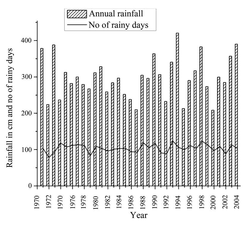
Figure 2. Annual rainfall and number of rainy days in a year at Igatpuri.
ployed to determine the volume of water to be stored.
2.4. Choice of RWH Structure
Once the volume of water to be stored is determined, the next step is to select the appropriate RWH structure, Analytical Hierarchy Process (AHP) is used for this purpose. The selected RWH structure should have two important characteristics: first one is assured quantity of water at any given time, second is good quality of water. Based on the topography and economics of the study area, three broad RWH structures are considered for detailed AHP analysis, they are:
• RCC water tanks: these are the closed structures with no seepage and less evaporation losses, least interference with atmosphere. They can provide reliable water supply with good quality with appropriate amount of treatment. But usually the construction costs are very high.
• Surface storage: these can be useful to store surface runoff effectively. They have lower construction cost but prone to seepage and evaporation losses. Also as they are open to surrounding environment and prone to various contaminations and biological activities.
• Ground water recharging: these are effective if sufficient good aquifers available. These have least cost, but the storage capacity depends on many external factors.
The above alternatives have their own advantages and disadvantages over others. The other points to be considered are reliable supply, water quality etc, instead of just going with cost benefit analysis, for this purpose one of the multi criteria decision making processes AHP is used.
2.5. Analytical Hierarchy Process (AHP)
AHP is a general theory of measurement used to derive ratio scales from both discrete and continuous paired comparisons [24]. It is used to determine the relative importance of a set of activities or criteria. The novel aspect and major distinction of this approach is that it structures any complex, multi-person, multi-criterion and multi-period problem hierarchically. Using a method for scaling the weights of the element in each level of the hierarchy with respect to an element (e.g., criterion) of the next higher level, a matrix of pair wise comparisons of the activities can be constructed where the entries indicate the strength with which one element dominates another with respect to a given criterion. This scaling formulation is translated into a principal eigen value problem which results in a normalized and unique vector of weights for each level of the hierarchy (always with respect to the criterion in the next level), which in turn results in a single composite vector of weights for the entire hierarchy. This vector measures the relative priority of all entities at the lowest level that enables the accomplishment of the highest objective of the hierarchy.
3. Results and Discussions
As indicated earlier the primary objective of the study is to select an appropriate RWH method and number of RWH structures for the industry which satisfies the hydrological, technical, economical and satisfaction criteria along with the implementable or amenable solution by the industry. For this purpose first the volume of water to be stored is assessed based on the prevailing hydrologic (rainfall-runoff) condition and demand in the industrial area. Then the appropriate method is selected using AHP based on satisfying criteria, the results are as follows:
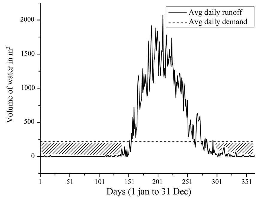
Figure 3. Mass balance representation of storage volume.
3.1. Mass Balance Method
In this method the basic assumption is that the demand in rainy (wet) months is met by supply (runoff) during same months. To meet dry months demand, water has to be stored during the rainy months, thus the storage capacity should be at least equal to the total water demand during dry months. Figure 3 shows the average daily rainfall and runoff from rooftop. Assuming the runoff coefficient as 0.9; the runoff from rooftop was estimated using rational method, with appropriate units the equation used for rational method is as follows:
Q = CiA(1)
where, Q – runoff, C - runoff coefficient, i - rainfall intensity and A - rooftop area The shaded portion in Figure 3 is the deficit volume in meeting the demand, this much of volume needs to be stored in the water rich period. Table 3 elaborates the monthly mass balance method. Since 95% of runoff occurs in four months (June, July, August, and September) the demand in these four months is met by the rainfall in these months. However the demand of remaining eight months should be met by the stored water in these four months. From Table 3 it is seen that the demand for eight months is 52,928 m3, hence the size of the reservoir should be 52,928 m3 or atleast 50,761 m3 (as the expected runoff during dry months is 2167 m3).
3.2. Ripple Diagram Method
This method considers the difference between the demand and supply over the period of time. To find out this difference, cumulative runoff is plotted against time. Cumulative demand is plotted and then superimposed on this graph starting from the peak of the dry period. If more peaks are available, the cumulative demand line may be started from each peak. Maximum difference

Table 3. Result of mass balance method.
between the supply and demand over the period of time is the capacity of RWH structure. This method considers two main assumptions:
1) if N years of data is available, the inflow and demands are assumed to repeat in cyclic progression of N year cycles;
2) the reservoir is assumed to be full at the beginning of dry season.
Figure 4 elaborates the procedure of Ripple diagram method. The maximum deficit works out to be 53,409 m3, and is the volume of water to be stored.
3.3. Analytical Method
In this method, the surplus or deficit for each time period is estimated and the cumulative is calculated. If there is a shift from surplus to deficit or vise versa in a time period, the cumulative is started afresh. Sample calculation for a year (1971) is given in Table 4. The same procedure has been followed for all the years (34 years) individually as well as continuously to take care of carry over storage. The cumulative deficits are listed to find the maximum deficit, the maximum deficit works out to be 53,409 m3 which is same as that of Ripple diagram method.
3.4. Sequent Peak Algorithm Method
This is a variation of the basic mass curve method to facilitate graphical plotting and handling of large data. In the sequent peak algorithm a mass curve of cumulative net flow volume against time (or residual mass curve) is used. This net flow is estimated using Equation (2).
NFt = Rt – Dt(2)
where, NFt-Net flow volume during the period t, Rt–Runoff volume during the period t, and Dt-Demand volume during the period t.
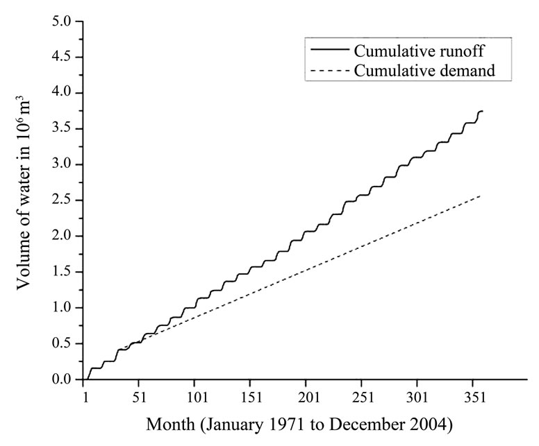
Figure 4. Ripple diagram method adopted.
Cumulative net flow for 34 years is plotted against time as shown in Figure 5. For any peak P1, the next following peak (P2) of magnitude greater than P1, is called a sequent peak. The lowest point between P1 and P2 is called trough T1. Likewise the sequent peaks Pi and troughs Ti can be found and the required RWH structure capacity (Si) is estimated as:
Si = Max of (Pi – Ti) i = 1,2,…,n (3)
It is evident from Figure 5 that the demand is less than the supply, thus the cumulative net flow is getting accumulating over the years. Values of peaks and troughs were found out from the graph and the differences were calculated. The maximum difference is 53,408.79 m3 and therefore the minimum volume of water to be stored should be 53,409 m³.
3.5. Appropriate Volume of Water to Be Stored
The comparative volume of rain water to be stored re-
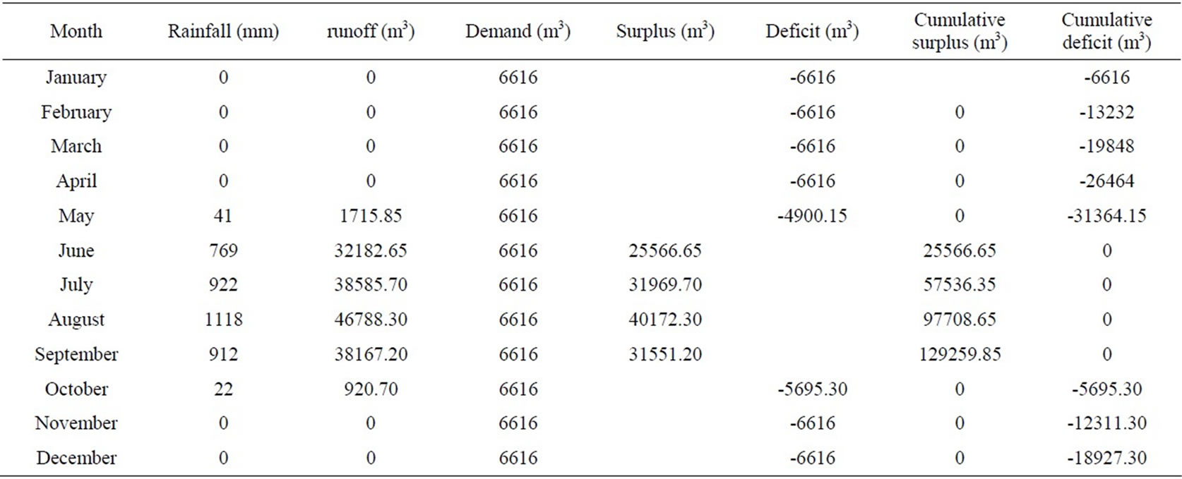
Table 4. Analytical method – sample calculations for the year 1971.
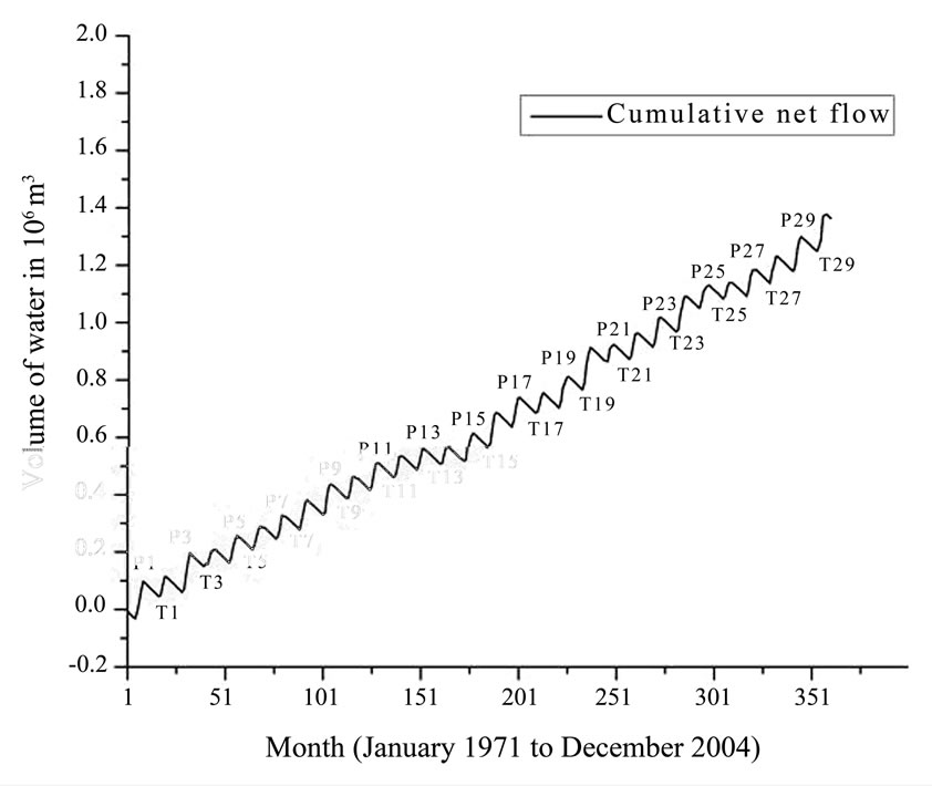
Figure 5. Results of Sequent peak algorithm method.
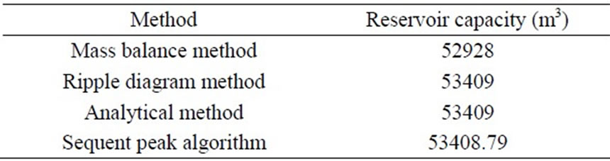
Table 5: Summary on volume of water to be stored
sulted from various methods to meet the demand is given in Table 5. From the above calculations and Table 5, it is clear that the volume of water to be stored should be 53,409 m3. For further calculations the reservoir capacity is considered as 55,000 m3.
3.6. Analysis of Appropriate RWH Method Using AHP
The above mentioned (Section 2.4) three alternatives RWH structure are evaluated against 16 attributes listed below using AHP. The initial AHP values for all the 16 attributes against the three alternative RWH techniques are shown in Table 6. Description of these attributes is given below. Attribute A1 to A7 are qualitative attributes while A8 to A16 are quantitative attributes.
1) Certainty of storage estimate is the confidence level by which estimated storage capacity of the structure can be trusted. The highest weightage is given for the structure which has maximum certainty in storage capacity estimation. The tanks are precisely designed to store stipulated volume of water and hence have maximum certainty in the estimate. In case of surface water storage large number of field surveys needs to be carried out to estimate the storage capacity. In case of ground water recharge it is extremely difficult o estimate the capacity of the aquifer and hence it is most uncertain of all. Thus the RCC tank has given maximum priority in calculating the final attribute matrix (Table 7).
2) Location / physical conditions is the location feasibility including the physical conditions like topology, subsurface structure etc. The study area has moderately undulating surface and more than 20 ha of open land is available. There is ample space available to construct a tank. Two locations are available for the construction of surface storage structures. The sub-surface strata mainly comprises of hard rock. This makes it very difficult for water to percolate, if aquifer recharge method is used. Thus for this attribute the tank has highest priority while ground water recharge has lowest priority. Surface storage has slightly less priority than that of tank.
3) Inspection and repairing feasibility is the feasibility to inspect the structure and to repair in case of any damage. The part of the tank above ground level is very easy to inspect and repair if necessary. But the part of the tank below ground level can be inspected only when it is empty. Similarly the wall of surface storage structure is

Table 6. Initial AHP attributes to identify most appropriate RWH structure.
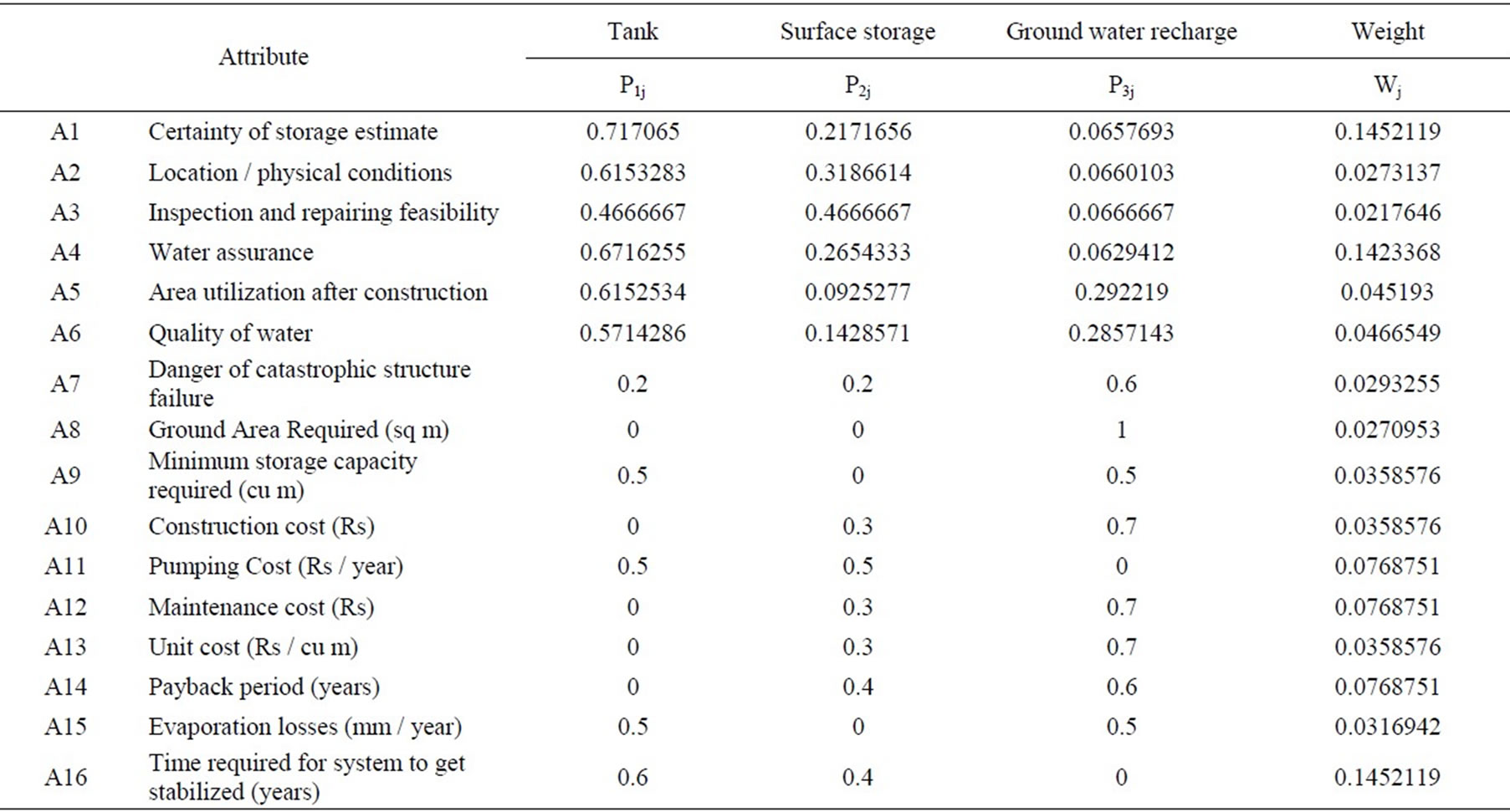
Table 7. Final attribute matrix.
very convenient to inspect but if there are any subsurface cracks or fractures, it is very difficult to inspect and repair. In case of ground water recharge, it is almost impossible to do any inspection. Thus tank and surface storage has same priority, greater than that of ground water recharge.
4) Water assurance is the confidence level by which the user can use the stored water from the RWH structure at any given time. In case of the tank, there is minimum evaporation and seepage loss, and hence the tank can provide assured water. The surface storage structure is prone to water losses in the form of evaporation and seepage; also sedimentation may reduce the storage capacity, hence surface storage is considered to have less assurance than that of the tank. The underground aquifers have least assurance.
5) Area utilization after construction is the possible area of the storage structure that is brought in use after construction. If due care is taken in design and construction of the water tank, the area above the tank may be brought under utilization. On the other hand the area of surface storage structure cannot be brought under any other use. Thus the tank has highest priority and surface storage has least. The ground water recharge structures are small in size and their presence does not affect day to day activities. Thus it has been given priority in between the other two alternatives.
6) Quality of water is the level of contamination to which the water is prone to. As water in tank can be completely isolated from air and sunlight, if filtered properly before its entry into the tank, it can be of good quality. The surface water has more chances of contamination with hazardous substances. Also due to direct contact of water with air and sunlight there is high possibility of plankton growth and other biological activities. Thus the tank has highest priority while surface storage has the least if water quality is considered. Ground water is naturally filtered. It has very less chances of any biological activity. But it may have the problem of dissolved minerals. Hence ground water storage has been given the priority in between the other two.
7) Danger of catastrophic structure failure: Open structures like surface storages and tanks are moreprone to this than ground water recharge. Even though due care is taken in the design and construction of water tank and surface storage structure, there is a risk of catastrophic structure failure due to unknown reasons. But in case of ground water recharge only few things like large scale earthquakes or heavy underground blasting may damage the natural aquifers. Thus ground water recharge has been given high priority and the remaining two have same priority but lower than that of the ground water recharge.
8) Ground area required is the total area required above surface for storage of the water. Depth of the water is assumed to be 4 m. Ground area required for tank and surface storage is calculated assuming the average depth of the water storage equal to 4 m. It will change depending on the designed depth of the storage. The area once used for the RWH cannot be used for any other usage except in ground water charge, hence has high priority and other two has no priority at all.
9) Minimum storage capacity required is the capacity of the structure for which the stored water will be sufficient to meet annual demand. Minimum storage capacity of the water storage structure is considered to depend on the water losses that the structure incurs. It is assumed that tank has negligible losses. Hence its minimum capacity should be equal to the minimum volume of water need to be stored to meet daily water requirement of the year. The minimum capacity of surface water storage is equal to the minimum volume of water need to be stored plus the total evaporation and seepage losses throughout the year. It is very difficult to find the water loss in underground aquifers. Since no loss in tank and ground water they have equal priority and higher than surface storage which has more losses.
10) Construction cost is the cost of the structure (in Indian rupees). An estimate of construction cost of the RCC tank, surface storage structure and recharge pits are carried out based on the prevailing cost of materials at the industry. Since the cost of tank is very high its priority is low, the ground water recharge requires less money and has high priority, the surface storage has priority in between these two methods.
11) Pumping cost influences the operation cost of the given alternative. Pump capacity is estimated based on the suction head, then the pumping cost is estimated assuming industrial power rate of Rs. 7 per unit. Since in ground water more number of wells and pumps are required its priority in this case is less than the other two methods.
12) Maintenance cost for tank includes cleaning the filters and the tank. For surface storage, de-silting and arresting the plankton growth are the main activities. For recharging structures, removal of sediments is the main maintenance task. Since ground water recharge does not require any maintenance it is given highest priority than other two methods.
13) Unit cost (Rs/ m³) is the cost per cubic meter of water stored. Unit cost of water storage is important in a sense that it gives insight of how much are the charges to store unit volume of water. It is the ratio of total cost (construction, pumping and maintenance cost) to the volume of water stored. Since the unit cost of water stored in tank is very high it is having less priority (no priority).
14) Payback period is the time taken to recover the cost of investment made on the RWH structure. To calculate payback period, construction cost and maintenance cost is considered. The data on existing water charges borne by the industry is also used to compare the pay back period.
15) Evaporation and seepage losses (in mm) are prevalent in open structures like surface storages and negligible in tanks, and ground water recharge methods.
16) Time required for the system to get stabilized. Construction of surface storage structure and ground water recharge structures is directly related to the natural hydro-geology of the area, hence it takes some time before the system begins to give consistent results. While the tank has no such conditions, it takes first cycle of rainy and dry periods to show the results and hence has high priority.
The discussion up till now is on the basis of the AHP. The criteria comparison matrix and technology comparison matrices for qualitative attributes are formulated based on above discussion. By processing these matrices, final attribute matrix was determined, and is shown in Table 7 along with the weight of each attribute. Table 7 contains values of quantitative as well as qualitative attributes represented between 0 and 1. Values of qualitative attributes are calculated by pair wise comparison. Values of quantitative attributes are arrived at by simple calculations. In AHP terminology, all the quantitative attributes in discussion are “cost attributes”. This means lower the value better is the alternative. Here 0 being of least desirable alternative and 1 being the most desirable alternative for the given attribute. These are nothing but the relative weightage of each RWH alternative on the scale of 0 to 1.
The results show that each alternative can be a most desirable for one attribute and least desirable for other attribute. For example, in case of construction cost, the tank is least desirable, and the groundwater recharge is most desirable and surface storage stands in between. But in “certainty of storage estimate”, tank is most desirable while the groundwater recharge is least desirable. In case of pay back period ground water recharge is most desirable, but when it comes to water assurance it has the lowest desirable method and also takes more time period to get consistence results. Also one may get wrong idea when considered only pay back period and if time taken to stabilization is not considered, as per the individual priority the ground water has high rank in pay back, but it is not assured because the system itself takes 10 years to get stabilized, thus the priority of individual attributes alone will lead to selection of wrong RWH method. So in order to make a choice between the available technology alternatives, one must know the importance of each attribute over other attributes so that the most desirable alternative with respect to most important attribute may be an ultimate choice.
In order to achieve this, the attribute weights are calculated by pair wise comparison of each attribute with every other attribute. Weights of the attributes (listed in

Table 8. Finals weights and ranks of the alternatives.
last column of Table 7) are nothing but the importance of each attribute over the other attribute quantified between 0 and 1. The sum of all the weights is necessarily equals to 1. Also the attributes representing assured storage of water (A1, A4 and A16) have higher weightage than other attributes. The weights of construction cost is less than the pumping and maintenance cost, thus giving less weight to one time investment and more weight to recurring cost. The normalized weights with respect to RWH structures are represented by “Pij” and the attribute weights by “Wj”. The final weight of each alternative is calculated by the Equation (4) and resulted final weights and ranking of the alternatives is shown in Table 8.
 i = 1,2,3 (4)
As a result of final weight, the RCC tank has highest weight (0.446) while the surface storage and groundwater recharge has equal weight of 0.277 each. It means that for given perspective of assured storage of water with good quality, the most appropriate alternative is the RCC tank. Though it has highest cost, it can assure the designed storage capacity with good quality of water which has more weightage in this case. By considering the uncertainty in groundwater storage in the study area, surface storage can be given second priority.
3.7. Most Effective Method to Install Tank
As a result of above AHP “RCC Tank” has resulted in as a most appropriate alternative RWH method. RCC tank can be installed in various combinations of size and number of tanks. Each combination has its own advan tages and disadvantages over the other in terms of cost, area required, safety and flexibility in operation. Eightdifferent combinations of size and number of tanks listed in Table 9 with respective to their costs and area required are considered for further selections. It is needed to find the most appropriate combination amongst these. It is observed that height of the tank less than 3 m result in very high area on the ground while height more than 4 m cause problems in inspection and repairing. So for comparison purpose, tanks of height 3 and 4 meter are considered. Also it is understood that excessive number of tanks are difficult to manage. So the number of tanks is limited to 4. It can be seen that cylindrical tanks have slightly less area requirement than that of square tanks. But they have higher construction cost. Also square tanks

Table 9. Alternatives of tank installation.

Table 10. Initial AHP table to identify right combination of tank size and number of tanks.

Table 11. Final weights and Ranks of the tanks.
are easy to construct. Considering this, four extreme alternatives of square tanks were chosen for comparison using AHP, Table 10 is the initial setup for the performance of AHP.
In case of safety, the risk of any damage gets divided on the number of tanks. If there is only one tank and it gets damaged, there is danger of loss of all the water. But in case of 4 tanks; if one is damaged, the water in remaining tanks would be safe. Also more number of tanks gives more flexibility in operation, maintenance, inspection and repairs. It can be seen that cost of combination of four tanks is higher than that of one tank. But four tanks have higher safety and flexibility of operation.
Thus depending on the weightage of attributes the choice of combination will defer. AHP is carried out to identify most appropriate combination out of these four combinations. The result of AHP is shown in Table 11. It can be seen that H4#4 has the highest weight (0.39). Thus, the installation of 4 square tanks with 4 m height is the most appropriate option considering cost, area utilization, safety and flexibility of usage.
The above results show that RWH is becoming one of the inevitable solutions to cater the increasing water demand and may also solve the dispute of water sharing among the users from a common source. If individual criteria are considered while selecting an appropriate RWH method, they are leading to wrong selection hence the selection of appropriate RWH method should be based on hydrological, demand pattern, storage requirement, economical, certainty of storage water, water assurance, payback period, time of stabilization etc. To have a methodological selection based on the various criteria, AHP is found to be very useful tool, not only for RWH method but also for number of RWH structures.Even though the appropriate RWH method and structures for a large scale industry is evaluated using a case study industrial area, this methodology can be applied to any other built up area (where less sediments flows into tanks) by using the relevant inputs namely the rainfall, demand and area available.
4. Conclusions
A large number of RWH methods are available in literature. However each method is site specific and demand specific. The RWH system depends on the topography, land use pattern, rainfall, demand pattern and economic status of the stake holder. Each structure requires detailed analysis of hydrology (rainfall and demand), to pography and other aspects. The present study is aimed at providing best techno-economic RWH structure so as to minimize or eliminate the dependency of the industry on purchased water. With the available data the first step is to find the volume of water need to be stored. All the four methods employed in the present study resulted in identical volume of 55,000 m3. Then the systematic methodology of AHP was applied to identify most appropriate RWH structure to store the required quantity of water with given conditions. As a result of this process “RCC tank” was identified as the most appropriate RWH structure for given requirement and conditions. Further, AHP was applied one more time to identify right combination of tank size and number of tank. As a result “four RCC cubical tanks with 4 m height” was identified as the most appropriate choice of RWH method for study area under given requirements and conditions.
REFERENCES
- R. N. Athavale, “Water harvesting and sustainable supply in India,” Centre for Environment Education, Ahmedabad, India, 2003.
- P. Arnold and C. Adrian, “Rainwater harvesting,” Intermediate Technology Publishing, London, 1986.
- R. K. Sivanappan, “Status and prospects of rainwater harvesting,” in proceedings of the workshop on rainwater harvesting, IIT Madras, pp. 1–10, 2001.
- Th. M. Boers and J. Ben-Asher, “A review of rainwater harvesting,” Agricultural Water Management, Vol. 5, pp. 145–158, 1982.
- C. A. David, “Guidance on the use of rainwater tanks,” National Environmental Health Forum Monographs Water Series, Australia, No. 3, 1998.
- D. Rees, “Partially Below Ground (PBG) tank for rainwater storage instructions for manufacture,” DTU Technical release series TR-RWH01, University of Warwick, UK, 2000.
- D. Rees and V. Whitehead, “Ferro-Cement Jar Instructions for manufacture (Based on the construction of a Ferro-cement Jar at Kyera Farm, Mbarara, Uganda),” DTU Technical release series TR-RWH06, University of Warwick, UK, 2000.
- CGWB, “Manual on artificial recharge of ground water,” Central Ground Water Board, Ministry of Water Resources, Government of India, New Delhi, 2007.
- S. K. Kamra, V. V. Dhruva Narayana, and K. V. G. K. Rao, “Water harvesting for reclaiming alkali soils,” Agricultural Water Management, Vol. 11, pp. 127–135, 1986.
- S. S. Grewal, S. P. Mittal, Y. Agnihotri, and L. N. Dubey, “Rainwater harvesting for the management of agricultural droughts in the foothills of northern India,” Agricultural Water Management, Vol. 16, pp. 309–322, 1989.
- H. N. Verma and P. B. S. Sarma, “Design of storage tanks for water harvesting in rainfed areas,” Agricultural Water Management, Vol. 18, pp. 195–207, 1990.
- G. N. Gupta, “Influence of rain water harvesting and conservation practices on growth and biomass production of Azadirachta Indica in the Indian desert,” Forest Ecology and Management, Vol. 70, pp. 329–339, 1994.
- A. M. Abu-Awwad and M. R. Shatanawi, “Water harvesting and infiltration in arid areas affected by surface crust: examples from Jordan,” Journal of Arid Environments, Vol. 37, pp. 443–452, 1997.
- A. Agarwal and S. Narain, “Dying wisdom: Rise, fall and potential of India’s traditional water harvesting systems,” State of India’s Environment-A Citizens’ Report No. 4, Centre for Science and Environment, New Delhi, India, 2003.
- D. N. Pandey, A. K. Gupta, and D. M. Anderson, “Rainwater harvesting as an adaptation to climate change,” Current Science, Vol. 85, No. 1, pp. 46–59, 2003.
- M. Qadir, Th. M. Boers, S. Schubert, A. Ghafoor, and G. Murtaza, “Agricultural water management in water starved countries: challenges and opportunities,” Agricultural Water Management, Vol. 62, pp. 165–185, 2003.
- A. K. Goel and R. Kumar, “Economic analysis of water harvesting in a mountainous watershed in India,” Agricultural Water Management, Vol. 71, pp. 257–266, 2005.
- S. N. Ngigi, H. G. Hubert Savenije, J. Rockstrom, and C. K. Gachene, “Hydro-economic evaluation of rainwater harvesting and management technologies: Farmers_ investment options and risks in semi-arid Laikipia district of Kenya,” Physics and Chemistry of the Earth, Vol. 30, pp. 772–782, 2005.
- D. D. Ozha and F. M. Golani, “Rehabilitation of traditional water harvesting systems of Rajasthan and their significance in present context,” Journal of the Institution of Public Health Engineers, Vol. 2006–07, No. 3, pp. 28–30, 2006.
- B. Panigrahi, S. N. Panda, and B. C. Mal, “Rainwater conservation and recycling by optimal size on-farm reservoir,” Resources, Conservation and Recycling, Vol. 50, pp. 459–474, 2006.
- M. Qadir, B. R. Sharma, A. Bruggeman, R. Choukr-Allah, and F. Karajeh, “Non-conventional water resources and opportunities for water augmentation to achieve food security in water scarce countries,” Agricultural Water Management, Vol. 87, pp. 2–22, 2007.
- R. Saha, P. K. Ghosh, V. K. Mishra, and K. M. Bujarbaruah, “Low-cost micro-rainwater harvesting technology (Jalkund) for new livelihood of rural hill farmers,” Current Science. Vol. 92, No. 9, pp. 1258–1265, 2007.
- M. Mehta and V. Jothiprakash, “Integrated rainwater harvesting system for a college campus in a metro city,”
- Journal of Indian Association for Environmental Management, Vol. 35, No. 3, pp. 122–126, 2008.
- T. L. Saaty, “Introduction to a modelling of social decision process. Mathematics and Computers in Simulation,” Vol. XXV, pp. 105–107, 1983.