Journal of Biomedical Science and Engineering
Vol. 5 No. 9 (2012) , Article ID: 22423 , 6 pages DOI:10.4236/jbise.2012.59067
Voltage profile generation for simultaneous multi-protein detection in Western blot analysis
![]()
1Department of Electrical and Computer Engineering, Indiana University-Purdue University Indianapolis, Indianapolis, USA
2Department of Biomedical Engineering, Indiana University-Purdue University Indianapolis, Indianapolis, USA
Email: *schien@iupui.edu
Received 9 June 2012; revised 5 July 2012; accepted 16 July 2012
Keywords: Western Blot; Protein Transfer; Voltage Control; Multiple Membranes
ABSTRACT
Western blotting is a popular technique for examining expression levels of proteins using gel-based electrophoretic fractionation followed by blotting and antibody reactions. Although this is a mature technique, one of the major limitations is the need to prepare an individual electrophoretic gel for each of the protein species to be analyzed. Since most analyses require the detection of multiple protein species, a procedure that allows utilization of a single gel for detecting multiple protein species should significantly save time and resources. In this paper, we developed a novel multi-protein detection device, which enabled simultaneous detection of several proteins species from a single electrophoretic gel. In this device, a protein transfer unit utilized a multi-anode plate that generated a non-uniform voltage profile. This voltage profile enabled uniform transfer regardless of molecular mass of proteins. In vitro experiments using samples, isolated from bone-forming osteoblast cells, showed that the expression levels of 5 - 7 different proteins were detectable in the presence and absence of mechanical stimulation that activated genes necessary for bone formation. The result supports the notion that through simultaneous detection of multiple protein species, the described device contributes to reduction in procedural time and sample amounts, as well as a removal of variations among multiple gels.
1. INTRODUCTION
Western blotting is a technique widely used to determine the relative amount of proteins in biological samples [1-3]. The procedure includes three major steps such as electrophoretic fractionation, transfer (blotting) to a membrane, and antibody reactions. In electrophoretic fractionation, protein samples in a gel under an electrical field are separated on the basis of their relative mobility, which in turn depends upon their molecular mass. Sizefractionated proteins, which are negatively charged and retained in the gel, are then transferred to a positively charged membrane such as nitrocellulose and polyvinylidene fluoride membranes [4,5]. The proteins, immobilized on the membrane, are detected using primary and secondary antibodies [6,7] and their expression levels are determined typically by chemiluminescence based imaging [8]. Although the above procedure has been well established, the procedure is labor intense using various chemical agents.
In investigating molecular signaling in response to chemical agents or mechanical stimuli, for instance, Western blotting is frequently employed to evaluate the expression levels of multiple proteins that are in many cases present in the phosphorylated and non-phosphorylated forms [9]. In a current procedure, scientists have to run the number of gels that is equal to the number of proteins of interest. The procedure is time consuming and it often requires a multitude amount of protein samples for running the required number of gels. Furthermore, running multiple gels adds to potential technical variations during loading and running gels. It is thus desirable if multiple membranes for analyzing various protein species can be generated from a single gel. This improved procedure can shorten a labor intensive procedure, increase efficiency and productivity, and save chemical agents and biological samples.
This paper presents a new approach that enables the generation of multiple membranes from a single gel. Specifically, it focuses on the improvement of the second step (blotting of proteins to membranes) by developing a multi-protein detection device and method. In the current procedure, transferring proteins is conducted under a constant electric field in which small proteins have high mobility and large proteins low mobility. In order to generate multiple membranes for proteins of any size from a single gel, we developed a protein transfer unit with a multi-anode plate and an associated voltage controller. We first established a procedure to identify a relationship between protein size and transfer speed, and derived an appropriate voltage profile to the multi-anode plate. We then constructed a regulator unit that generated the required voltage profile.
We validated the described multi-protein detection device using protein samples isolated from osteoblast cells and examined the expression levels of various proteins in the presence and absence of mechanical stimulation. The selected proteins included β-actin (used as reference), β-catenin, Akt, ERK, and p38, as well as the phosphorylated isoforms of Akt, ERK, and p38. The phosphorylated isoforms were known to be elevated in response to mechanical stimulation [10].
2. DESIGN AND THEORY
The current semi-dry protein transfer device is to transfer one protein species from a single gel to a single membrane. The device requires a repetitive operation in case multiple protein species need to be analyzed (Figure 1(A)). The novel device, developed herein, allows multiple blotting from a single gel (Figure 1(B)). We described the hardware and software design of this multiprotein detection device in Section 2.1 and the method for identify the voltage profile in Section 2.2. Section 2.3 explained the identification of blotting time.
2.1. Design of a Multi-Protein Detection Device
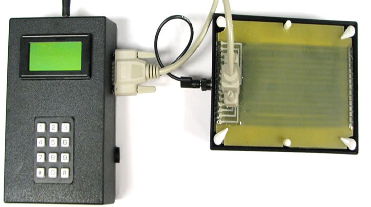
The described multi-protein detection device consists of two major components: a controller unit (Figure 2(a)) and a protein transfer unit (Figure 2(b)). The whole device is powered by a DC power adapter, and the two components are connected by a DB15 cable and a ground cable. The protein transfer unit has a common cathode plate and a multi-anode plate. The controller unit provides multiple independent voltage signals through the multi-channel cable to multi-anodes. With a properly regulated blotting voltage profile, large proteins can be transferred with higher voltage and small proteins with lower voltage so that all proteins are transferred at the same speed.
2.1.1. Control Unit
The operation of the control unit requires entering the protein transfer conditions and the number of membranes to be generated. The controller unit takes this information and specifies the voltage level for each anode and blotting duration for each membrane. After one operation of protein transfer, the controller generates an audio sound and displays a text message that asks the user to change a membrane for the next transfer.
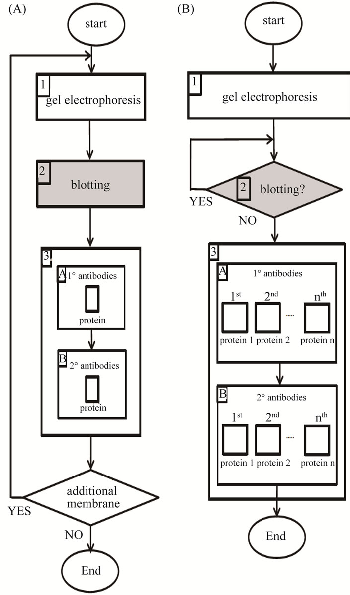
Figure 1. Western blot procedure. (A) Current device; (B) Multiprotein detection device.
 (a) (b)
Figure 2. Multi-protein transfer device. (a) Controller unit; (b) Protein transfer unit.
The computer based controller unit generates proper average voltages to each of the anodes. The average voltage levels are achieved through multiple pulse width modulated (PWM) DC signals of different duty cycles [11]. Each PWM signal is individually amplified by an amplifier and applied to one of the anodes (Figure 3). Using PWM of different duty cycles simplifies the hardware design in generating varying average voltages.
2.1.2. Protein Transfer Unit
The protein transfer unit contains a common cathode plate and a multi-anode plate with 15 individually crafted anodes. Each anode is shaped in a 4 mm wide strip, and the space between the adjacent anodes is set to 1 mm. There is a guide rail on the cathode to ensure that the top of the gel can be properly aligned to the anode 1. The operation of the protein transfer unit requires stacking an extra thick blotting paper, a SDS gel, an Immobilon-P membrane, and the other extra thick blotting paper in this order, on the common cathode (Figure 4). The multianode plate is then placed on the top of this stack and locked into place. The described design ensures that the gel is aligned properly with the anodes for uniform transfers of multiple membranes.
2.2. Voltage Profile Generation
A voltage profile consists of a set of voltages applied to each of the anodes of the multi-protein detection device. The determination of the voltage profile requires three steps. The first step is to determine the transfer distance of proteins of various molecular mass on the gel in electrophoresis with a given running voltage. The transfer distance is affected by the gel composition, the running
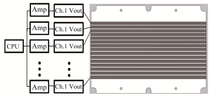
Figure 3. Driving circuit of the multi-protein transfer device.
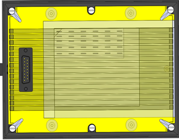
Figure 4. Top view of the protein transfer unit.
buffer composition, and the voltage applied in electrophoresis for size fractionation. The second step is to identify the migration speed of proteins of different mass at a specific blotting voltage, and the third step is to determine blotting voltage. This last step assigns proper voltage to each of the anodes and makes all proteins be transferred at the same speed. In this paper, we determined the voltage profiles for a standard transfer condition as follows:
• Gel (Mini-PROTEAN TGX Precast gel; 10% with 10 well combs, 50 µl well volume);
• Electrophoresis
Ø Running buffer (Tris 25 mM, glycine 192 mM, SDS 0.1%, pH 8.3);
Ø Voltage (100 V for 10 min, followed by 150 V for 30 min);
• Blotting
Ø Transfer buffer (Tris 3.03 g; glycine 14.4 g; water 787 ml; and methanol 200 ml);
Ø Membrane (Immobilon-P; 8.6 cm × 7.4 cm);
Step 1. This step was to find transfer distances of proteins of various molecular mass in electrophoresis for size fractionation. Assuming that proteins with equal mass migrate equally in speed, we used markers of known molecular mass for mobility measurement. To build a relationship between protein mobility and molecular mass, we evaluated mobility of a set of 5 protein markers (25 - 175 kD) at constant voltage of 100 V for 10 min and then 150 V for 30 min (Figure 6(a)). The distance travelled by each of the protein markers was recorded as 6.25 mm for 80 kD, 11.1 mm for 58 kD, 15.9 mm for 45 kD, and 20.8 for 30 kD. Eq.1 is a polynomial curve that best fits migration distance verses molecular mass:
d = α + βm + γ/m(1)
where d is the migration distance, m is molecular mass, and the parameters were determined as α = 5.242, β = –0.3778, and γ = 556.3.
Since the centers of multi-anodes are located as distances of 2 mm, 7 mm, 12 mm, 17 mm, 22 mm, 27 mm, etc., the molecular mass of proteins at the distances of the anodes 1 - 5 should be 175 kD, 99 kD, 61 kD, 42 kD, and 31 kD, respectively, according to Eq.1.
Step 2. The second step was to determine migration speed. Ideally we need to determine it at 15 V that is used during a blotting procedure. However, the mini-gel in this study is only 1 mm thick and it is difficult to measure migration speed through this thickness. Thus, we determined migration speed along the length of the gel (8 cm). The measured migration distance over time is used to derive the migration velocity (mm/s) and is plotted in Figure 5. The migration velocities of various proteins were approximated by Eq.2 using the best-fit polynomial curve:
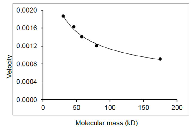
Figure 5. Protein velocity as a function of molecular mass at 15 V.
v = a + bm + c/m (2)
where ν is the migration velocity in mm/s, m is molecular mass in kD, and the parameters were estimated as a = 9.8 × 10⁻⁴, b = 1.5 × 10⁻⁶, and c = 2.9 × 10².
Using Eq.2, the transfer velocities of the proteins of different masses at the distances of the anodes 1 - 5 (175 kD, 99 kD, 61 kD, 42 kD, and 31 kD, respectively) can be evaluated.
Step 3. The third step was to determine blotting voltage for given transfer speeds. Since migration speed were affected by buffers as well as a stack of mattresses and a membrane, the relationship of the protein mobility rate and the driving voltage used in electrophoresis needed to be re-evaluated. Here, we assume that protein mobility and its associated driving voltage during size fractionation is proportional to that in a blotting procedure with a proportion constant k1. The row 1 of Table 1 shows the mobility of each protein in electrophoresis, while the row 2 its mobility during blotting. The row 3 indicates the desired voltage that should be applied to each of the anodes. We assigned V1 as the known maximum blotting voltage and v1 as the lowest mobility protein under the anode 1. Then the voltage to the anode 2, v2, was estimated using the constant voltage of 15 V for the anode 1:
V:15 = v1:v2(2)
From Eq.2, it is derived:
V = 15*v1/v2 = k2/v2(3)
where k2 = 15*v1. Based on the above prediction, we derived appropriate blotting voltage to proteins with various sizes (Table 1).
According to Table 1, the derived voltages for the anodes 1 to 5 were 15.0 V (175 kD), 11.7 V (99 kD), 9.7 V (61 kD), 8.4 V (42 kD), 7.3 V (31 kD), respectively.
2.3. Blotting Timing
To determine the blotting time for each membrane, we experimented the blotting duration with respect to the
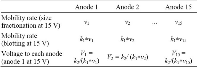
Table 1. Estimated voltages to the anodes to achieve uniform mobility.
signal intensities of proteins we selected in this study. Figure 6 shows signal intensity of proteins as a function of blotting time. We thus employed 5 min as blotting time for each membrane. The result showed that 5 membranes could be generated using 8 µl of protein samples at 2 µg/ml. By increasing the loading volume to 16 µl, we reduced the blotting time to 4.5 min and generated 7 membranes from a single gel.
3. EXPERIMENTS
The aforementioned multi-protein detection device and operation method was used to detect 8 different proteins including β-actin (Sigma), β-catenin, eIF2α, Erk, Erk-p (phosphorylated Erk), Akt, Akt-p (phosphorylated Akt), p38, and p38-p (phosphorylated p38).
3.1. Protein Harvest
Protein samples were harvested from MC3T3 osteoblast like cells. Cells were cultured on collagen coated glass slides in MEM medium containing 10% fetal bovine serum and antibiotics. At 80% confluence, cells were serum starved for 12 h, and they were subjected to uniform flow shear stress at 10 dyn/cm2 for 1 h [9]. Protein samples were isolated in a RIPA buffer.
3.2. Protein Electrophoretic Fractionation
Sixteen µl of protein samples at 2 µg/µl were loaded to 10% SDS gels, and size fractionated using 100 V for 10 min followed by 150 V for 30 min.
3.3. Protein Transfer Using the Multi-Protein Detection Device
Proteins, immobilized in SDS gels, were electro-transferred to Immobilon-P membranes (Millipore) using the described multi-protein detection device and predetermined voltage profile in Section 2. We generated five membranes from a single gel, five minutes for each membrane.
3.4. Protein Detection
After transferring proteins to the membranes using the multi-protein detection device, the membranes were incubated overnight in a blocking solution. The membranes
 (a)
(a)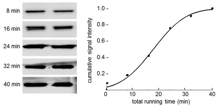 (b)
(b)
Figure 6. Signal intensity as a function of transferring time. (a) Signal intensity of β-actin; (b) Signal intensity of Akt.
were then incubated for 1 h with primary antibodies specific to β-actin (Sigma), β-catenin, eIF2α, Erk, Erk-p (phosphorylated Erk), Akt, Akt-p (phosphorylated Akt), p38, and p38-p (phosphorylated p38), followed by 45 min incubation with secondary antibodies. The protein levels were assayed using an ECL Western blotting detection kit (Amersham), and signal intensities were quantified using a luminescent image analyzer (LAS-3000, Fuji Film).
3.5. Results
Five membranes were used to detect the expression levels of five protein species including β-catenin (92 kD), Akt-p (60 kD), β-actin (45 kD), Erk (42/44 kD), and eIF2α (37 kD). The blot images clearly showed that it was possible to detect five different proteins at 37 - 92 kD using a single gel (Figure 7(a)).
To further validate the described device, we examined the protein samples isolated from osteoblast cells in response to fluid flow induced shear stress (Figures 7(b) and (c)). Compared to the control samples that received no flow treatment, the flow treated samples presented upregulation of the phosphorylated forms of p38, Erk, and Akt. In the first experiment (Figure 7(b)), the phosphorylation of Erk and p38 was elevated while the levels of other proteins such as p38, Erk, and β-actin were unchanged. In the second experiment (Figure 7(c)), the levels of the phosphorylated isoforms of Erk, p38, and Akt were increased without changing the total levels of Erk, p38, and Akt.
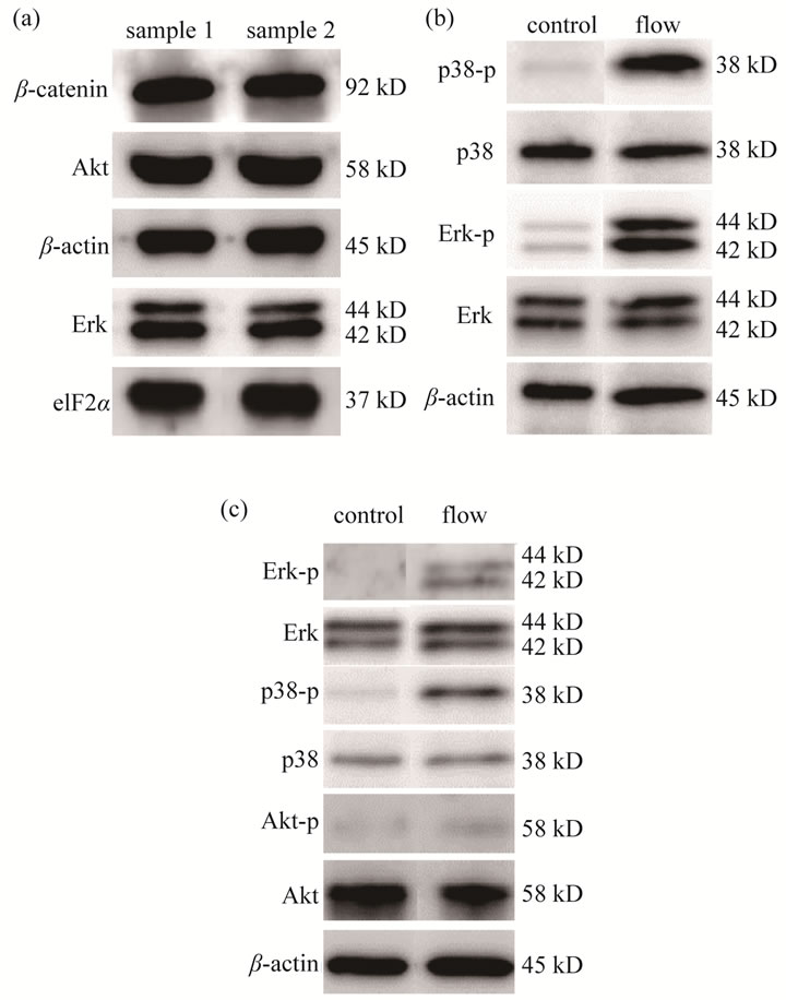
Figure 7. Western blot results from a single gel using the multi-protein detection device. (a) Western blot results for proteins including β-catenin, Akt, β-actin, Erk, and eIF2α; (b) Western blot results in response to flow treatment for β-actin, Erk, Erk-p, p38, and p38-p; (c) Western blot results in response to flow treatment for β-actin, Akt, Akt-p, p38, p38-p, Erk, and Erk-p.
4. DISCUSSION
The described multi-protein detection device allows the production of multiple membranes from a single gel. The protein transfer unit of this device consists of a common cathode and a multi-anode plate, which applies a nonuniform voltage profile. Under this voltage profile, the migration speed of proteins of different molecular mass is regulated to be equal. The capability of the described device was experimentally validated using the protein samples isolated from bone-forming osteoblast cells in the presence and absence of flow treatment. Flow treatment is known to upregulate the phosphorylated form of Erk, p38, and Akt, and the Western blot result clearly shows their elevated expression levels [12]. The existing Western blot procedure, which allows only one membrane per gel, may require multiple gels and protein samples. Using the described device, five to seven membranes can be generated per gel.
An examination of the cumulative distribution function of β-actin and Akt shows that the transfer of protein samples under a constant voltage as a function of time holds a non-linear relationship. A unique feature of the described device is its multi-anode plate for the distribution of a non-uniform voltage profile. By applying the described voltage profile, the amount of migration of protein samples of all different sizes is controlled linearly to transfer time. This linear relationship is a unique feature of the described device for the generation of multiple membranes from a single gel.
The current study employed a standard condition for running a gel. A mini gel with 1 mm thickness was used. The thickness of gel is an important factor in generating multiple membranes from a single gel. It is possible to modify the voltage profile and support different types of gel and experimental conditions.
5. CONCLUSION
The multi-protein detection device was developed and validated. The device was capable of generating five to seven membranes from a single gel. The multi-anode plate was regulated to provide a proper voltage profile that enabled a uniform transfer of proteins regardless of their molecular size. The robust design provided good sample alignment and reproducible transfer operations. The results herein support the notion that the described device is useful to increase efficiency of Western blot analysis by saving time, chemical agents, and protein samples.
6. ACKNOWLEDGEMENTS
The authors appreciate Nancy Tanjung, Andy Chen, and Jordan Kane for technical support. The study was in part supported by FORCES funds provided by Indiana University-Purdue University Indianapolis.
REFERENCES
- Hagyousif, A.M., Chong, V.J., Yokota, H. and Chien, S. (2010) Development of a novel protein multi-blotting device. Journal of Biomedical Science and Engineering, 3, 1125-1132. doi:10.4236/jbise.2010.312146
- Towbin, H., Staehelin, T. and Gordon, J. (1979) Electrophoretic transfer of proteins from polyacrylamide gels to nitrocellulose sheets: Procedure and some applications. Proceedings of the National Academy of Sciences of USA, 76, 4350-4354. doi:10.1073/pnas.76.9.4350
- Burnette, W.N. (1981) “Western blotting”: Electrophoretic transfer of proteins from sodium dodecyl sulfatepolyacrylamide gels to unmodified nitrocellulose and radiographic detection with antibody and radioiodinated protein. Analytical Biochemistry, 112, 195-203. doi:10.1016/0003-2697(81)90281-5
- Chen, H.-W. (2003) Semi-dry electroblotter. Wealtec Enterprise Co. Ltd., San Francisco, 1-7.
- Szewczyk, B. and Kozloff, L.M. (2004) A method for the efficient blotting of strongly basic proteins from sodium dodecyl sulfate-polyacrylamide gels to nitrocellulose. Analytical Biochemistry, 150, 403-407. doi:10.1016/0003-2697(85)90528-7
- Avrameas, S. and Guilbert, B. (1971) A method for quantitative determination of cellular immunoglobulins by enzyme-labeled antibodies. European Journal of Immunology, 1, 394-396. doi:10.1002/eji.1830010518
- Kuhlmann, W.D., Avrameas, S. and Ternynck, T. (1974) A comparative study for ultrastructural localization of intracellular immunoglobulins using peroxidase conjugates. Journal of Immunological Methods, 5, 33-48. doi:10.1016/0022-1759(74)90043-X
- Mathews, S.T., Plaisance, E.P. and Kim, T. (2009) Imaging systems for westerns: Chemiluminescence vs. infrared detection. Protein Blotting and Detection, 536, 499-513. doi:10.1007/978-1-59745-542-8_51
- Hirasawa, H., Jiang, C., Zhang, P., Yang, F. and Yokota, H. (2010) Mechanical stimulation suppresses phosphorylation of eIF2alpha and PERK-mediated responses to stress to the endoplasmic reticulum. FEBS Letters, 584, 745-752. doi:10.1016/j.febslet.2009.12.028
- Wang, D., et al. (1999) Isolation and characterization of MC3T3-E1 preosteoblast subclones with distinct in vitro and in vivo differentiation/mineralization potential. Journal of Bone and Mineral Research, 14, 893-903. doi:10.1359/jbmr.1999.14.6.893
- Giorgos Lazaridis (2009) PWM Modulation. http://pcbheaven.com/wikipages/PWM_Modulation/
- Hamamura, K., Swarnkar, G., Tanjung, N., Cho, E., Li, J., Na, S. and Yokota, H. (2012) RhoA-mediated signaling in mechanotransduction of osteoblasts. Connective Tissue Research, 53, 398-406. doi:10.3109/03008207.2012.671398
NOTES
*Corresponding author.