Journal of Biomedical Science and Engineering
Vol. 5 No. 3 (2012) , Article ID: 18107 , 7 pages DOI:10.4236/jbise.2012.53019
A finite element modeling of the human lumbar unit including the spinal cord
![]()
1Laboratoire de Recherche Matériaux, Mesures et Applications, Institut National des Sciences Appliquées et de Technologie (INSAT), Université de Carthage, Tunis, Tunisia
2Tunisian Group of Spine and Spinal Cord Study and Research, Tunis, Tunisia
3SNC-Lavalin, Montréal, Canada
Email: fafa.benhatira@insat.rnu.tn
Received 2 December 2011; revised 31 December 2011; accepted 18 January 2012
Keywords: Numerical Modelling; Three Dimensional Reconstruction; Lumbar Unit; Spinal Cord
ABSTRACT
The purpose of this present work is to provide a tool to better understand mechanically related pathologies of the lumbar unit and the spinal structure by providing spinal cord deformations in different loading cases. In fact, spinal cord injury (SCI) resulting from a traumatic movement leades to a deformation of the neural and vascular structure of the spinal cord. And since the magnitude of the spinal cord stress is correlated with the pressure of the vertebral elements, stresses will be computed on all theses components. Physical properties of the vertebrae, various ligaments, the discs, and the spinal cord are described under simple loading as compression, and combined loading, flexion and lateral bending to evaluate the pressure undergone by different components of the lumbar unit. A nonlinear three-dimensional finite element method is used as a numerical tool to perform all the computations. This study provides accurate results for the localisation and the magnitude of maximum equivalent stress and shear stress on the lumbar unit and especially for the spinal cord. These results showed that stresses are more important when a compression of 500 N is combined with a flexion and a lateral bending. In particular, shear stresses are maximum for the spinal cord and the four intervertebral discs for the case of a flexion of 3.8 N.m and a lateral bending of 6.5 N.m.
1. INTRODUCTION
Spinal cord injury (SCI) is usually a consequence of a traumatic movement resulting in a deformation of the neural and vascular structure of the spinal cord exceeding their structural and physiological limits. As a matter of fact, the neurological damage is due to different loading combination. The identification of the parameters, leading to neurological deficit during walking (Neutrogenic claudication) can help to understand and prevent all these phenomena. Based on clinical observations, the physiological changes of soft tissues throughout life is another factor to be taken into account. They could reduce the available space for the neural structures (spinal cord, medullar cone and roots) [1]. This effect is amplified by vertebrae slip due to the weakness of vertebral facets, ligamentous ossification, vertebral joint fusion and also osteoporosis. This is emphasises the need of the correlation between the vertebral elements pressure and the one taken on the spinal cord element.
In general, the increase of stenosis during walking and prolonged standing position leads to neutrogenic claudication and in common to sphincter disorder. In some cases, these degenerative lesions exist whereas the clinical phenomena did not appear during rest.
In medical revues, the spinal component displacement (mainly the intervertebral disc) have been often related to neurological deficits or complications after lumbar spine manipulations. These observations have been made in [2]. Also in [3], the authors showed that the compression of the spinal cord of a fresh corpse produces a transverse crack in the spinal cord. The authors demonstrated that the damaged surfaces of this crack deviate. It is then essential to connect biomechanical observations obtained through computations to these various physiological observations.
From biomechanical point of view, many authors provided some answer to how different components of the spinal column interact with each other under different loading situations but none of these works examined the spinal cord behavior in the lumbar unit. One example of these works is the one presented in [4] where a three dimensional nonlinear finite element analysis of the mechanical behavior of the L2-L3 disc-vertebrae unit is performed with a focus in the use of tissue engineered intervertebral discs under complex loads. Also, in [5], authors presented an original work on the formulation of wrapping elements sliding over solid body edges and used to study the loadbearing capacity of simplified beamrigid body thoracolumbar and lumbosacral) spines. In [6], the authors presented a two-dimensional axisymmetric finite element model of a spinal motion segment consisting of the first lumbar vertebral body and adjacent intervertebral disc to allow the inclusion of a centrally located tumour in the vertebral body. In [7], the author presented a three-dimensional finite element model to study the static and vibrationnal loads and to analyze the stress distribution on the intervertebral disc of a L4-L5 lumbar unit. In their work taken from [8], the authors presented recent experimental evidences concerning the distribution of forces and moments acting on the lumbar spine and neural arch. The authors mainly conducted experimental works on cadaveric motion segments to investigate the distribution of the stresses on the lumbar spinal unit. All these works detailed the behavior of different components of the lumbar unit without including the spinal cord. The major article related to the study of the spinal cord is the one presented in [9]. In this article, the author stated that the loss of normal pattern of spinal motion causes pain and/or neurological dysfunction and that the system of spine may be divided into three subsytems 1) the spinal column; 2) the spinal muscle; and 3) the neural control unit. The authors precised that the two first subsystems have been widely studied in the litterature, wheareas, the neural zone was found more sensitive and is less studied in the biomechanical litterature.
Finally, the biomechnical study of cervical flexion myelopathy throughout a finite element model presented in [10] is another important work found in the litterature dealing with the computations of stresses on the spinal cord. However, the presented results have been obtained for the upper part of the spine (the cervical spine) whereas our model deals with the lower part of the spine (the lumbar vertebrea).
A numerical biomechanical model will then be presented in this article to describe the mechanical behavior of a complete functional human spinal unit; this anatomical model consists in five lumbar vertebrae, four intervertebral discs, the physiological ligaments, capsular articular parts, and spinal cord (terminal cone).
The biomechanical study of this model has been established to study the influence of the stresses on all the elements of this model and to explain advanced state of neurological deficit signs.
2. MATERIAL & METHOD
2.1. Finite Element Method
Three dimensional finite element model is built up using the computed tomography (CT) of the L1-L5 lumbar unit including mechanical properties designed for the five vertebrae, the four intervertebral discs, the ligaments (anterior, posterior, flavum, interspinous and supraspinous), articular and capsular parts, and spinal cord (cauda equina).
The numerical modelling based on a finite element methods (FEM) simplifies the structure whether it is anatomical or not by reflecting its mechanical properties. This method requires specification of the geometry of the modeled structure, the loads and pressure applied to that structure, and the elastic properties of the components. The geometry is subdivided into small regions (elements) and the differential equations governing the deformation of solids are numerically solved. Computed quantities include local deformations in response to the applied loads, as well as the corresponding stresses.
Three steps are needed to accomplish these tasks:
1) Definition of the geometry of the column constitutive parts;
2) Establishement of the laws which govern the behavior of every part of the lumbar spinal unit;
3) Evaluation of the model by performing a series of numerical computations.
2.2. Geometric Model
Concerning the first step, the total obtained meshed model representing the lumbar is given in Figure 1. The geometry of the vertebrae have been obtained by segmentation of series of images using SliceOMatic 4.3. In the Finite Element software Ansys, several procedures are developed to make the change of reference and to bring the vertebrae in the same reference. The volumes of each vertebra are assembled.
The discs have been added to fit between two vertebrae as well as the totality of the physiological ligaments. Moreover, as it is suggested in most described physiological cases, the spinal cord is added to fit into the medullar canal which is between the first and the second
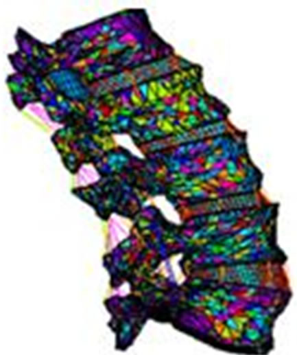
Figure 1. The obtained meshed lumbar unity.
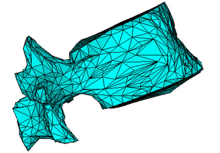
lumbar vertebra. The annulus fibers and the cartilaginous plates are respectively shown in the same figure. Details of the meshing of vertebrae are shown in Figure 2(a). As we can see, the vertebrae is reproduced by using the scanned images.
The appropriate meshing for the disc is shown in Figure 2(b) showing the geometry of the nucleus and the annulus. Finally, the fitted spinal cord between the first and the second lumbar vertebra is shown in Figure 2(c).
2.3. Material Properties
The second step consists in modeling the vertebrae as an elastic orthotropic structure with Young’s Modulii and Poisson’s ratios obtained through the mineral bone density. The maximun and the minimum values of the the young modulii (Ex, Ey, Ez) taken in the three directions (x, y, z) are summeraized in the Table 1. The same table gives the values of the shear modulus (Gxy, Gyz, Gxz) and
 (a)
(a)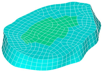 (b)
(b)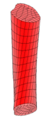 (c)
(c)
Figure 2. (a) The meshed geometry of L1; (b) Geometry of the nucleus and annulus; (c) The spinal cord fitted in the medullar canal.
the three Poisson ratios (vxy, vxz, vzx). For the intervertebral disc which is divided into the annulus and pulposus part, Young’s Modulii and Poisson’s ratios were taken in the litterature [11]. Cartilages fibers are also taken into account. The material properties are specified in the same table. All these parts are simplified as a structure with an isotropic and linear elastic behavior. According to the work presented in [12], the spinal cord tissue has roughly analogous rheological properties as ligamentous tissue. An average elastic modulus of the spinal cord described in [13] is found to be equal to 1.40 MPa. An isotropic elastic behavior is also established for this physiological part.
3. RESULTS AND DISCUSSION
3.1. Boundary Conditions
The third step is performed through different loadings using the finite element method, FEM. The boundary
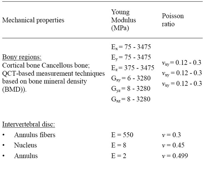

Table 1. Material properties for the lumbar unit L1-L5.
conditions are specified in Figure 3.
The boundary conditions for the different cases use a fixed bottom of the lumbar human unit (in the three directions) and the appropriate load for each presented case.
For the case of compression, a pressure is assigned to the top surface of the geometry to ensure the homogeinity of the applied load. The pressure is computed by dividing each load by the area located on the first lumbar L1.
Equivalent Stress
The equivalent von Mises stress given in the following equation is used to evaluate the maximum value. This value is taken as a limit to the ultimate elastic stress for most structural computation, Equation (1).
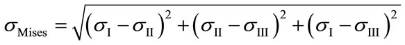 (1)
(1)
where ,
,  and
and  are the principal stresses.
The results will be given for the whole structure. Results obtained for the bony structure (vertebrea) and the intervetbral disc are presented here after followed by the maximun (critical values) of stresses obtained for the spinal cord.
3.2. First Load Case: Compression
Figure 4 shows the details of a subdivision of the vertebra into six different points. The three first ones are related to the posterior region (POST), respectively external (out), medium (mid) and internal (in). In the same way, three points are taken in the anterior region of the vertebra (ANT), respectively, external (out), medium (mid) and internal (in).
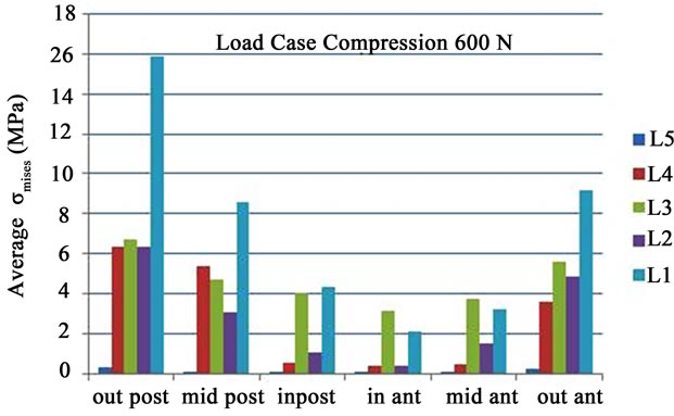
Figure 5(a) gives the average of the von Mises equivalent stresses  obtained for the five lumbar vertebrae for these specific six points in the case of a load of 600 N. It is clear that the stresses are higher for more important external loads and that the most loaded vertebra is the bottom one (L5). The peaks of stresses are located at the outer posterior points.
The disc is also split into six different parts as done for each vertebra. As known, the disc is composed of nucleus pulposus and annulus fibrosis. In the normal healthy disc, the pulposus hydrated core exerts a hydrostatic pressure (pressure intradiscal (IDP) on fibers of the annulus fibrosis [12].
First Case Data Analysis
Figure 5(b) gives the average values of  for the various points of the disc located between the 4th and the 5th vertebra (L45). The values of
  indicate that the nucleus pulpous can absorb some compressive loads and that the maximum values are obtained for the outer posterior and anterior points, which are located in the annulus region as pointed out in [14]. The same authors showed

Figure 3. Boundary conditions with load on the top of the vertebrae L1.
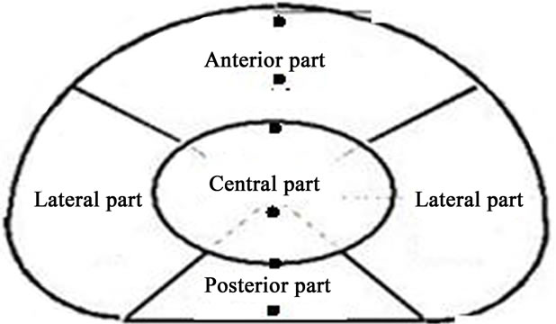
Figure 4. Locations of the six points used to plot the equivalent stress distribution.
 (a)
(a)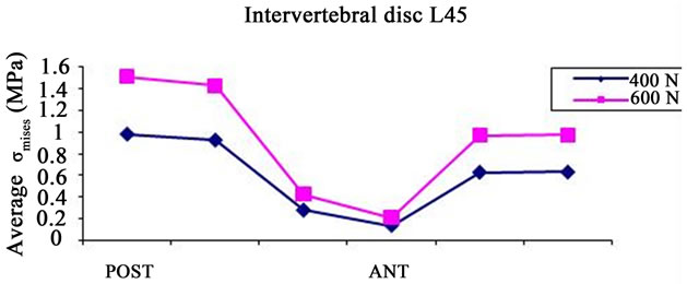 (b)
(b)
Figure 5. (a) Average σmises distribution for the five vertebra, P = 600 N; (b) Average σmises distribution for the intervertebral disc L45.
that the high stresses found in the annulus fibrous are due to the fibers whose stiffness rises rapidly with strains. These observations had encouraged us to include the annulus fibrous in our model. In the work of [3], it is shown that the compression of the spinal cord induces a transverse crack and that critical flexion can cause damage on the surfaces of spinal column. The mean values for the equivalent pressure ( , Figure 5(a)) and the standard deviations (SD) for the five lumbar vertebra are given in Table 2. The highest value is found for the fifth vertebrae (7.201 MPa ± 5.1097 MPa).
Median and standard deviation of  (Figure 5(b)) are also computed for the intervertebral disc located between the fourth and the fifth vertebrae, for the two compressive cases (400 N and 600 N). The highest values were found for the second case (0.97072 MPa ± 0.52255 MPa) whereas the data obtained for the first compressive case is (0.633035 MPa ± 0.33931 MPa).
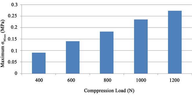
The values attached to the spinal-cord for the same cases of compression (ranging from 400 N to 1200 N) are presented in the Figure 6(a). The maximum of the  stress is found to vary linearly with the compressive load. The computed maximum values do not exceed 0.3 MPa. In [15], it is reported that the failure stress for nerve roots of spinal cord was approximately 0.257 MPa with a Young Modulus of 1.3 MPa whereas as listed in Table 1, the Young modulus is chosen in this work to be 1.4 MPa (13). The isovalues given in Figure 6(b) show that one can locate exactly the maximum value on the spinal cord for a load of 400 N. The maximum value found in the case of 1200 N compression for the spinal cord (0.3 MPa ) can be compared to the value for the disc located between the 5th and the 4th vertebrae (5.257 MPa).
3.3. Second Load Case: Combined Loads (Compression, Flexion and Lateral Bending)
The following computations are presented for cases of simple flexion, lateral bending and a combination of both by imposing moments on the first lumbar vertebra L1 in order to transfer them to the complete lumbar segment. The values of moments are summarized in Table 3. All these loading cases were combined with an initial load of axial compression of 500 N (which is the average value of loading force taken for a person of a 70 Kg) to find and to locate the loading which would lead to the highest internal  and
and .
.
Second Case Data Analysis
The Figure 7 shows the distribution of  and the shear stresses taken in the (xy) plane (
 ) for vertebrae, the four discs and the spinal cord. Shear movement represented usually by vertebrae slipping toward spinal cord is a factor of narrowing available space for roots and spinal cord. Indeed, in [16,17] a discussion of how the spinal

Table 2. Mean and SD values of σmises for the five vertebra in a case of a compression of 600 N.
 (a)
(a)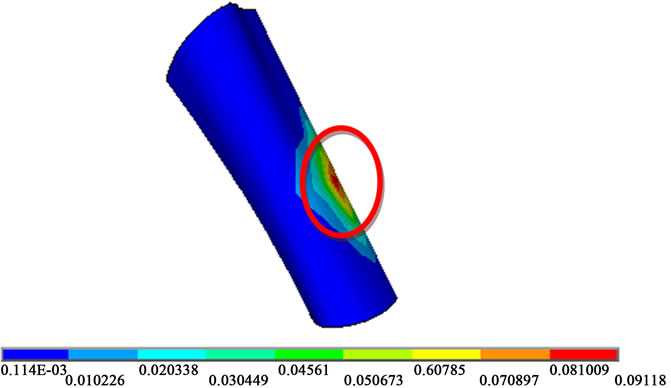 (b)
(b)
Figure 6. (a) Maximum σmises for the spinal cord; (b) Location of the maximum σmises on the spinal cord for a load of 400 N.
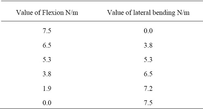
Table 3. Specific loads (flexion and lateral bending).
cord deforms as a result of changes in posture or biomechanical alterations of the spine is presented. The authors measured a 16% closing of the vertebral canal under
 (a)
(a)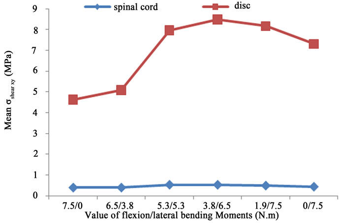 (b)
(b)
Figure 7. (a) Average σshear xy distribution for the vertebrae and the discs; (b) Average σshear xy distribution for the discs and the spinal cord.
extension, causing stenosis. However, no value for the bending moments has been mentioned (extension or flexion). In our computations, any measurement of canal area reduction could not be estimated since contact elements have been added to the link between different part of the lumbar unit (between the spinal cord and the available space between L1 and L2). As for pure compression cases, the values of the  are very high for vertebrae compared to the spinal cord one Figure 7. In fact, vertebra ensures a protection for the spinal cord and prevents critical loads to be transferred to this physiological part. These figures also pointed out that the maximum value (
 and
and ) occur almost for the same situation of a flexion of 5.3 N.m and a lateral bending of 5.3 N.m, for the vertebrae. However, the maximum stresses
  and
and  occur in the case of a flexion of 3.8 N.m combined with a lateral bending of 6.5 N.m, of the spinal cord and the disc. This is probably due to the difference in the material properties between the bones, the disc, and the spinal cord. Table 4 shows the mean values as well as the standard deviations for the
  and
and  obtained for the combined load cases, Figure 7(a). The highest mean value is obtained for the vertebra (105.1MPa ± 20.267 MPa). Computations made on shear stress (
 ) (Figure 7(b)) show that the highest mean value is also found for the vertebra (8.2122 MPa ± 0.53536 MPa).
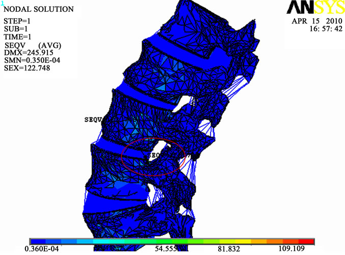
Figure 8(a) shows the maximum values of  distribution for the whole lumbar unit for a flexion of 5.3 N.m and a lateral bending of 5.3 N.m with the location of the highest value obtained on the 3rd vertebrae. This result is of course different from the one obtained in a pure
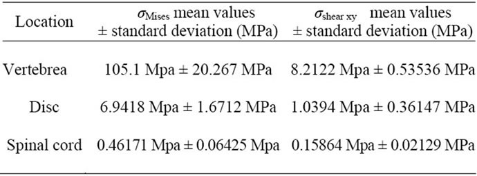
Table 4. Mean and SD values of σMises and σshear xy for the vertebra, disc and spinal cord in a case of combined loads.
 (a)
(a)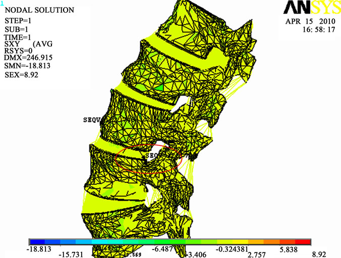 (b)
(b)
Figure 8. (a) Maximum σmises distribution; (b) Maximum σshear xy distribution (Flexion of 5.3 N.m and a lateral bending of 5.3 N.m).
compression load case. It is also different from the one obtained for  (Figure 8(b)).This means that the maximum shear stress (slipping of vertebrae) is located in a different place from the location of the maximum of the compressive equivalent stresses.
Finally, Figure 8(b) shows that the maximum distribution of  for the spinal cord and for the four intervertebral discs occurs for the case of a flexion of 3.8 N.m and a lateral bending of 6.5 N.m. The value of shear stress for the spinal cord (0.329 MPa) is relatively low compared to the one located on the discs (0.61 MPa). It is due to the low stiffness of the spinal cord.
4. CONCLUSIONS
A non linear three dimensional FE model of a lumbar spine is built up to simulate the loading of the spine. Compressive loads of 400 N and 600 N have been applied to this segment. The obtained results showed that maximum of  is located at the articular apophasis of the fifth lumbar vertebra.
Observations of compression combined with flexion and lateral bending were conducted to obtain critical values  and
and . These computations clearly show that having critical values for the spinal cord could be used to better understand some pathology, such as, neurological deficit. Also, the computations showed that the maximum equivalent stresses for flexion combined with lateral bending is stronger than those due to simple flexion or lateral bending. The presented biomechanical model could be improved in the future by considering the viscoelastic behavior of the disc and soft tissues and by introducing an appropriate model of damage in the equations governing the behavior law. Finally, this work can be improved to investigate the spinal cord injury by taking into account more precisely the mechanical properties of such soft tissue and précising the correlation between the vertebral elements pressure and the spinal cord one.
REFERENCES
- Jacobs, W.B. and Gehlings, M.G., (2008) Ankylosing spondylitis and spinal cord injury: Origin,incidence, management, and avoidance. Neurosurgery Focus, 24, E12. doi:10.3171/FOC/2008/24/1/E12
- Morandi, X., Riffaud, L., Houedakor, J., Amlashi, S.F.A, Brassier, G. and Gallien, Ph., (2004) Caudal spinal cord ischemia after lumbar vertebral manipulation. Joint Bone Spine, 71, 344-337. doi:10.1016/S1297-319X(03)00154-4
- Breig, A., Renard, M., Stefano, S. and Renard, C. (1982) Régénération de la moelle après hémisection par relâ- chement biomécanique et immobilisation chirurgicale. Anatomia Clinica, 4, 2-7. doi:10.1007/BF01798897
- Yao, J., Turteltaub, S.R. and Paul, D.P., (2006) A three dimensional nonlinear analysis of the mechanical behavior of tissue engineered intervertebral discs under complex loads. Biomaterials, 27, 377-387. doi:10.1016/j.biomaterials.2005.06.036
- Shirazi-Adl, A. and Parnianpour, M. (2000) Load-bearing and stress analysis of the human spine under a novel wrapping compression loading. Clinical Biomechanics, 15, 718-725. doi:10.1016/S0268-0033(00)00045-0
- Whyne, C.M., Hu, S.S. and Lotz, J.C. (2001) Parametric finite element analysis of vertebral bodies affected by tumors. Journal of Biomechanics, 34, 1317-1324. doi:10.1016/S0021-9290(01)00086-0
- Tak-Man, J., Zhang, Ch.M. and Chow, D.H-K. (2003) Biomechanical responses of the intervertebral joints to static and vibrational loading: A finite element study. Clinical Biomechanics, 18, 790-799. doi:10.1016/S0268-0033(03)00142-6
- Dolan, P. and Adams, M.A. (2001) Recent advances in lumbar spinal mechanics and their significance for modeling. Clinical Biomechanics, 16, s8-s16. doi:10.1016/S0268-0033(00)00096-6
- Panjabi, M.M. (2003) Clinical spinal instability and lower back pain. Journal of Electromyography and Kinesiology, 13, 371-379. doi:10.1016/S1050-6411(03)00044-0
- Yoshihiko, K., Hideo, K., IKazuhiko, Ch., Yasuaki , I., Takanori, K., Shunichi, K., Daisuke, H., Kentaro, Y. and Toshihiko, T. (2008) Biomechanical study of cervical flexion myelopathy using a three-dimensional finite element method: Laboratory investigation. Journal Neurosurgery Spine, 8, 436-441. doi:10.3171/SPI/2008/8/5/436
- Wang, J.L., Parnianpour, M., Shirazi-Adl, A., Engin, E., Li, S. and Patwardhan, A. (1997) Development and validation of a viscoelastic finite element model of an L2/L3 motion segment. Theoretical and Applied Fracture Mechanics, 28, 81-93. doi:10.1016/S0167-8442(97)00032-3
- White, A. and Panjabi, M. (1990) Clinical biomecanics of the spine. 2nd Edition, Philadelphia.
- Mazuchowski, E.L. and Thibault, L.E. (2003) Biomechanical properties of the human spinal cord and pia mater. 2003 Summer Bioengineering Conference, Key Biscayne, 25-29 June 2003.
- Champain, N. (2004) Recherche des facteurs biomécaniques dans l’aggravation des scolioses idiopathiques. Thèse Biomécanique, ENSAM, 2004.
- Singh, A., Lu, Y., Chen, Ch. and Cavanaugh, J.M. (2003) Mechanical properties of spinal nerve roots subjected to tension at different strain rates. Journal of Biomechanics, 39, 1669-1676. doi:10.1016/j.jbiomech.2005.04.023
- Harrison, D.E, Cailliet, R., Harrison, D.D, Troyanovich, S.J. and Harrison, S.O. (1999) A review of biomechanics of the central nervous system—Part I: Spinal canal deformations resulting from changes in posture. Journal of Manipulative and Physiological Therapeutics, 22.
- Harrison, D.E., Cailliet, R., Harrison, D.D., Troyanovich, S.J. and Harrison, S.O. (1999) A review of biomechanics of the central nervous system—Part II: Spinal cord strains from postural loads. Journal of Manipulative and Physiological Therapeutics, 22.