Natural Science
Vol.6 No.11(2014), Article ID:47908,8 pages
DOI:10.4236/ns.2014.611085
The Misleading Use of “Enthalpy” in an Energy Conversion Analysis
Heinz Herwig
Institute for Thermo-Fluid Dynamics, Hamburg University of Technology, Hamburg, Germany
Email: h.herwig@tuhh.de
Copyright © 2014 by author and Scientific Research Publishing Inc.
This work is licensed under the Creative Commons Attribution International License (CC BY).
http://creativecommons.org/licenses/by/4.0/


Received 26 May 2014; revised 30 June 2014; accepted 9 July 2014
ABSTRACT
The frequently used thermodynamic state quantity enthalpy H turns out to be very problematic when applied in an energy conversion analysis. Due to the fact that H combines two terms, the internal energy U and the product pV, the interpretation of what H means in physical terms is often obscure and leads to various misinterpretations. Several examples are given and interpreted twice, i.e. with and without referring to enthalpy.
Keywords:Enthalpy Misinterpretation, Energy Conversion Analysis

1. Introduction
In basically all thermodynamic text books the enthalpy H is introduced and used in an energy conversion analysis, predominantly in open thermodynamic systems. For example, Moran and Shapiro ([1] page 81, 128) introduce H in the following way:
In many thermodynamic analyses the sum of the internal energy U and the product
of pressure p and volume
![]() appears. Because the sum
appears. Because the sum
 occurs so frequently in subsequent discussions, it is convenient to give the combination
a name, enthalpy, and a distinct symbol, H. By definition
occurs so frequently in subsequent discussions, it is convenient to give the combination
a name, enthalpy, and a distinct symbol, H. By definition
 Since
Since
 and
and
![]() are all properties, this combination is also a property… The appearance of the sum
are all properties, this combination is also a property… The appearance of the sum
 in the control volume energy equation is the principal reason for introducing enthalpy
previously. It is brought in solely as a convenience.
in the control volume energy equation is the principal reason for introducing enthalpy
previously. It is brought in solely as a convenience.
While Cengel ([2] page 52) under the headline “Enthalpy—A combination Property” writes:
In the analysis of certain types of processes, particularly in power generation
and refrigeration (...), we frequently encounter the combination of properties . For the sake of simplicity and convenience, this combination
is defined as a new property, enthalpy, and given the symbol H.
. For the sake of simplicity and convenience, this combination
is defined as a new property, enthalpy, and given the symbol H.
Once a new physical quantity is introduced, one seeks for its physical interpretation. With the enthalpy often it is just the “combination property” explanation as in the two examples given above. Sometimes, however, H is named “heat content” or “total heat” (see [2] for details) without giving a really convincing justification for these names as a general description of what H stands for.
2. Enthalpy: Motivation, Definition, and Interpretation
In the examples given in the introduction the control volume energy equation was mentioned as the principal reason for introducing enthalpy. Before this is explained in more details some general considerations about control volume balance equations and the quantities appearing in these equations are necessary.
2.1. Control Volume Balance Equations
The state of a thermodynamic system is characterized by several physical quantities like mass, energy and entropy which can be subject to a balance with respect to a control volume. In this kind of balance the change of a certain quantity in the system is exclusively due to a transport of this quantity across the control volume boundaries when the quantity under consideration is a conserved quantity (like the thermodynamic total energy). For non-conserved quantities (like entropy) changes may also be due to creation and/or destruction of the quantity.
In these equations two types of quantities appear which are very different in nature:
• state quantities, characterizing a (instantaneous and local) state of the system at a certain time and location within the system. Let i and j be different times or locations then a general state quantity here will be named
 or
or
![]() and changes are denoted by
and changes are denoted by

• process quantities, characterizing a process by which the state quantities
of the system are changed between their states i and j. A general process quantity
here will be named
![]() with the double index ij indicating that the process occurs between i and j.
with the double index ij indicating that the process occurs between i and j.
Mathematically, both kinds of thermodynamic quantities are very different: state quantities have a total differential (and thus are path independent), process quantities do not have it.
With n state quantities and m process quantities involved, a general control volume balance equation for a steady thermodynamic system between two cross Sections 1 and 2, for example, reads
 (1)
(1)
Only when balance equations are developed according to this general form a clear physical interpretation can be given.
2.2. The Energy Balance (1. Law of Thermodynamics)
The well-known “1. Law of Thermodynamics” applied to a finite open control volume
exemplified for a steady energy conversion is illustrated in
Figure 1. The state quantity is the total thermodynamic energy, here introduced
as specific energy
 which is either
 or
or . It has three parts which are the internal energy
 , the kinetic energy
 and the gravitational potential energy
 . Process quantities are the work done (
 ) and the heat transferred (
 ) with respect to the control volume.
According to its general form (1) the energy balance equation reads with 1 for the inlet and 2 for the exit cross section
 (2)
(2)
The process quantities on the r.h.s. of (2) are
• energy transfer across the control volume boundaries between 1 and 2 in form
of heat, i.e. due to local temperature gradients, which lead to a local wall heat
flux . Then
 with A as transfer area is
 (3)
(3)
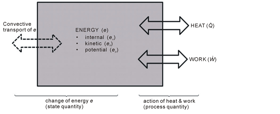
Figure 1. State and process quantities involved in a control volume balance for an open system.
• energy transfer across the control volume boundaries between 1 and 2 in form of work, i.e. due to local forces with moving points of action. In an open system there are two work terms which are
 : shaft work, transferred by the shaft of a turbine or a pump
 : flow work, transferred at the inlet and outlet by the action
of pressure forces
: flow work, transferred at the inlet and outlet by the action
of pressure forces
 moving their point of action with the velocity
 , so that with

 (4)
(4)
The quantities involved in the energy conversion in an open system between 1 and 2 are sketched in Figure 2.
2.3. The Enthalpy-Form of the Energy Balance
When Equation (4) is formally introduced in Equation (2) the energy balance can be written as
 (5)
(5)
Here the specific enthalpy h appears by combining the state quantity u and the process
quantity pv. Note that now
 is the only work term left since
 “disappeared” in h. This form of the energy equation is frequently used for open
systems, rewritten as
“disappeared” in h. This form of the energy equation is frequently used for open
systems, rewritten as
 (6)
(6)
with the specific heat transfer
 and the specific shaft work
 . In this equation

is often interpreted as an “energy change” of the fluid within an energy conversion process. For example in Warhaft ([3] page 92) it reads with respect to pumps and turbines: They are both devices that change the energy of the fluid by means of work interactions.
In the examples given below it will be shown, however, that combining state and process quantities by using h gives rise to various misinterpretations.
2.4. The Non-Enthalpy-Form of the Energy Balance
The “1. Law of Thermodynamics” balances the total thermodynamic energy which is the sum of a mechanical and a thermal part. Without introducing the enthalpy h it reads in a form corresponding to that of Equation (6) above
 (7)
(7)
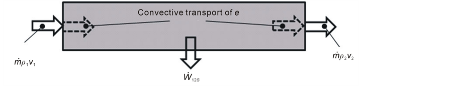
Figure 2. Control volume balance for a steady energy conversion in an open system.
Note that now both work terms ( and
and ) appear on the r.h.s. of Equation (7).
For further analyzing energy conversion systems one can deduce the partial energy equations for the mechanical and the thermal part of the total thermodynamic energy. This is done by multiplying the momentum equation with the velocity in order to get the mechanical partial energy equation. This equation in fluid mechanics is known as Bernoulli equation, see for example Herwig [4] . The thermal partial energy equation then appears when the mechanical equation is subtracted from Equation (7)—guaranteeing that the total thermodynamic energy is the sum of its two parts (mechanical and thermal).
In terms of Equation (7) the two partial equations are:
mechanical: (8)
(8)
thermal: (9)
(9)
Now the specific dissipation
 appears which is not explicitly present in Equation (7). The physical background
is the following:
appears which is not explicitly present in Equation (7). The physical background
is the following:
Dissipation of mechanical energy converts mechanical into internal energy. This
energy devaluation process happens, when flow work is not converted into shaft work
but increases the internal energy of the fluid. Thermodynamically this corresponds
to an entropy generation in this irreversible process. Since, however, flow work
 and internal energy increase
 both appear in the total energy equation, the dissipation term
 does not explicitly show up in the total energy equation (6) or (7). Only in equation
(8) the specific dissipation
does not explicitly show up in the total energy equation (6) or (7). Only in equation
(8) the specific dissipation
![]() appears in a way which is appropriate for the determination of this quantity.
appears in a way which is appropriate for the determination of this quantity.
As mentioned before the specific dissipation is accompanied by an entropy generation
 according to
 (10)
(10)
with
 as specific entropy generation and T as thermodynamic temperature. Knowing
![]() or
or
 is essential when losses in a flow field should be determined. For a detailed discussion
of this aspect of an energy conversion see Herwig and Schmandt
[5] .
is essential when losses in a flow field should be determined. For a detailed discussion
of this aspect of an energy conversion see Herwig and Schmandt
[5] .
As far as the enthalpy is concerned, h does not only combine a state and a process
quantity, but also one that appears in the thermal energy equation (u in Equation
(9)) and one that is part of the mechanical energy equation (pv as part of
 in Equation (8)). That is why the enthalpy-form (6) of the energy balance cannot
be further detailed by determining the mechanical and the thermal parts of it separately.
Then, however, the dissipation term
in Equation (8)). That is why the enthalpy-form (6) of the energy balance cannot
be further detailed by determining the mechanical and the thermal parts of it separately.
Then, however, the dissipation term
![]() cannot be determined within the energy considerations based on the enthalpy concept.
cannot be determined within the energy considerations based on the enthalpy concept.
3. Energy Conversion Examples
Since the introduction of h is motivated by energy conversion considerations four such examples will be analysed based on Equation (6) using h as the crucial “energy quantity” and compared to an analysis avoiding the enthalpy, based on Equations (7)-(9). The interpretation of the results will be named “enthalpy interpretation” and “nonenthalpy interpretation”, respectively.
3.1. Energy Conversion in a Turbine (Dissipation Neglected)
Figure 3 shows a turbine operated with water which
may be part of a pumped storage hydro power station. Assuming incompressible fluid
(![]() ), an adiabatic process (
), an adiabatic process ( ), equal cross sections (
 ), and equal elevation head (
 ), Equation (6) reduces to (note:
 )
)
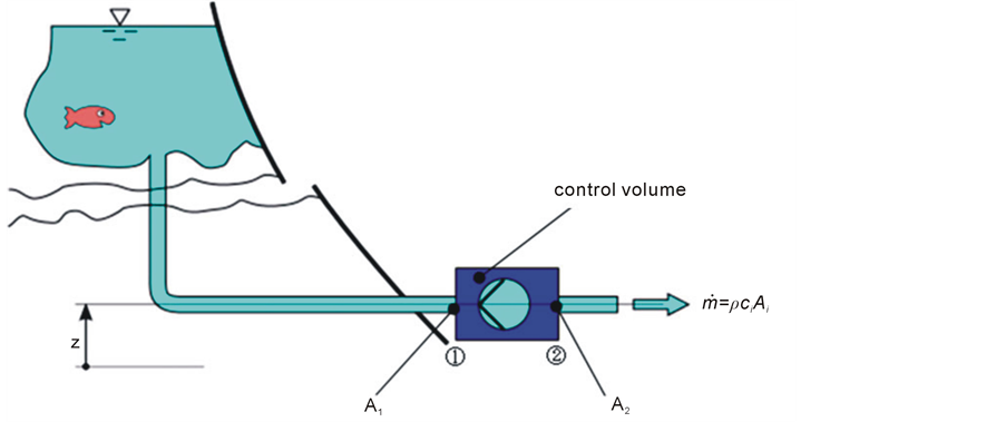
Figure 3. Control volume around the turbine in a pumped storage hydro power station.
 (11)
(11)
or:
 (12)
(12)
The enthalpy interpretation is:
Energy of the fluid is converted into shaft work of the turbine.
This, however, contradicts the fact that the energy e of the fluid remains unchanged, because there is no change in
• internal energy, because u for an incompressible fluid is a function of T only and the temperature remains (basically) the same.
• kinetic energy because
 holds
holds
• potential energy because
 holds.
From Equation (7) we get
 (13)
(13)
or:
 (14)
(14)
The non-enthalpy interpretation is:
Flow work is converted into shaft work of the turbine without changing the energy of the fluid.
3.2. Energy Conversion in a Turbine (Dissipation Accounted for)
In real turbines dissipation occurs, often reducing the available work by the order of 10%.
Based on Equation (6) one gets
 (15)
(15)
which is the same result as before, c.f. Equation (11).
The enthalpy interpretation is:
There is no recognizable effect of dissipation on the shaft work of a turbine.
From Equation (9) we get
 (16)
(16)
so that Equation (7) now becomes:
 (17)
(17)
or: (18)
(18)
The non-enthalpy interpretation is:
There is a recognizable effect of dissipation on the shaft work of a turbine. Shaft work is reduced by dissipation (which increases the internal energy of the fluid).
3.3. Heating the Fluid Ahead of the Turbine (Dissipation Neglected)
The example from section 3.1 is resumed but now with a heat transfer of strength
 ahead of the turbine as sketched in Figure 4.
From Equation (5) we get for this case
 (19)
(19)
or: (20)
(20)
The enthalpy interpretation is:
From comparing Equation (20) with Equation (12) one might conclude that
 increases the shaft work though it is not clear how h behaves under the heat transfer.
From Equation (9) we get (with indices adopted)
 (21)
(21)
so that Equation (7) now becomes:
 (22)
(22)
or with
 since
since
 only
only
 (23)
(23)
The non-enthalpy interpretation is:
There is no influence of
 on the shaft work, the internal energy is increased by
 leaving the flow work unchanged.
3.4. Throttling of an Incompressible Fluid
Figure 5 shows a throttle which may be part of
a heat pump or refrigeration cycle and in which an incompressible liquid flows through
the throttle. Equation (6) with ,
,
 ,
,
 and
and
 reduces to
 (24)
(24)
The enthalpy interpretation is:
The energy of the fluid obviously remains unchanged, “though” dissipation leads
to a reduction of the pressure level from
![]() to
to
 which is the desired effect.
Equations (8) and (9), however, show that flow work by the irreversible dissipation
process (c.f. Equation (10)) increases the internal energy of the fluid, so that
(with
 and
and ) also the total thermodynamic energy of the fluid is increased.
The non-enthalpy interpretation is:
The total thermodynamic energy of the fluid is increased by the action of flow work, which leads to a pressure reduction.
4. Conclusion: The Misleading Aspects of Enthalpy
Enthalpy, according to its definition
 is a combination of state quantities and thus itself is a state quantity.
When, however, H or its specific versions h is used in control volume balance equations for an energy conversion analysis only U continues to be a state quantity while pV comes from a process quantity (flow work). Furthermore, the introduction of h in the total energy equation prevents its interpretation as the sum of the partial energy equations for the mechanical and the thermal energy. Then, however, the dissipation term does not appear explicitly (and thus cannot be determined).
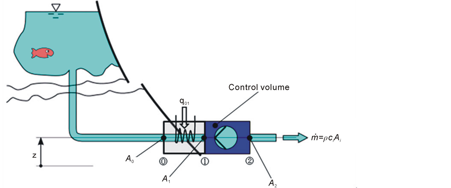
Figure 4. Heating the fluid ahead of the turbine.
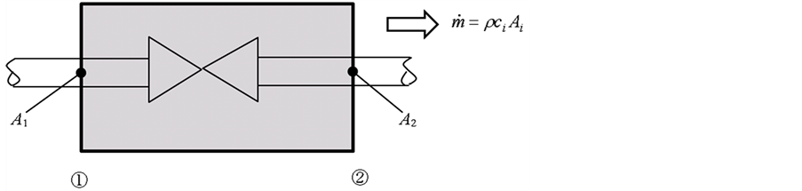
Figure 5. Control volume around a throttle.
The examples given in Section 3 show several shortcomings of the enthalpy interpretation. Main aspects in this respect are:
• The energy of the fluid and its changes in conversion processes is misinterpreted. Flow work may (as in a throttle) or may not (as in a turbine) change the energy of the fluid. Taking h as an “energy” leads to wrong conclusions.
• The introduction of h combines one term of the thermal energy equation (u in (9)) and one term of the mechanical energy equation (pv in (8)). Then, however, the detailed interpretation in terms of mechanical versus thermal energy is no longer possible.
• The explicit appearance of the dissipation term
![]() only occurs when the partial energies are balanced. This, however, is suppressed
by introducing h, so that
only occurs when the partial energies are balanced. This, however, is suppressed
by introducing h, so that
![]() is not accessible and thus cannot be determined.
is not accessible and thus cannot be determined.
With all these points in mind the final recommendation is: try to avoid enthalpy in an energy conversion analysis.
References
- Moran, M.J. and Shapiro, H.N. (1996) Fundamentals of Engineering Thermodynamics. Wiley and Sons, New York.
- Cengel, Y. (1997) Introduction to Thermodynamics and Heat Transfer. McGraw-Hill Companies, New York.
- Warhaft, Z. (1997) An Introduction to Thermal-Fluid Engineering. Cambridge University Press, Cambridge.
- Herwig, H. (2006) Strömungsmechanik. Springer-Verlag, Berlin.
- Herwig, H. and Schmandt, B. (2014) How to Determine Losses in a Flow Field: A Paradigm Shift towards the Second Law Analysis. Entropy, 16, 2959-2989. http://dx.doi.org/10.3390/e16062959
Nomenclature
 : general state quantity
 : area (m2)
![]() : general process quantity
: general process quantity
 : velocity (m/s)
 : specific energy (J/kg)
![]() : specific internal energy (J/kg)
: specific internal energy (J/kg)
![]() : specific kinetic energy (J/kg)
: specific kinetic energy (J/kg)
![]() : specific gravitational potential energy (J/kg)
: specific gravitational potential energy (J/kg)
 : energy (J)
 : energyflux (W)
![]() : specific enthalpy (J/kg)
: specific enthalpy (J/kg)
 : enthalpy (J)
![]() : massflowrate (kg/s)
: massflowrate (kg/s)
![]() : pressure (N/m2)
: pressure (N/m2)
 : heat flux (W/m2)
![]() : heat transfer rate (W)
: heat transfer rate (W)
![]() : entropy generation rate (W/K)
: entropy generation rate (W/K)
 : specific entropy generation (J/kgK)
 : thermodynamic temperature (K)
 : specific internal energy (J/kg)
 : specific volume (m3/kg)
![]() : volume (m3)
: volume (m3)
![]() : specific shaft work (J/kg)
: specific shaft work (J/kg)
![]() : specific flow work (J/kg)
: specific flow work (J/kg)
 : work transfer rate (W)
 : elevation head (m)
![]() : specific dissipation (J/kg)
: specific dissipation (J/kg)